1
Installation and Operating Instructions for Automatic Low Voltage Capacitor Banks
2.3.2
Power connections
3.1.1.2 Manual parameter setting of RVC
The capacitor bank has to be connected to the network with
the correct phases and with a clockwise rotating field.
Connect the PE and N conductors or PEN conductor to the
terminals provided in the capacitor bank.
Press the “Mode”-button until “MAN SET” and the parameter
cos ϕ is displayed. Choose the desired value with “+” and “-“
buttons. Press the “Mode”-button twice until the parameter
“c/k” is displayed. Calculate and enter the C/k value:
Q c
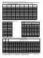
or see Appendix A4
C / k = ( 0 .6 . . .0 .7 ) ⋅
U ⋅
The connection between PE and N is necessary in a TN-C
system, otherwise it has to be removed.
Refit all covers.
2.3.3
Fault signalling system
For external use of the alarm signals of the power factor
controller there is a pair of terminals (M, M) in the control
terminal bar of the capacitor bank. These terminals are
connected with a floating contact which is closed if
• the desired cos ϕ is not reached (Target cos ϕ for RVC,
Alarm cos ϕ for RVT)
• A voltage disconnection is present
• An alarm threshold is violated (RVC, RVT)
• The internal temperature of the controller is above 85°C
Please also refer to the controller manual.
3
Commissioning
Check the electrical and mechanical connections. Perform a
visual check before commissioning the system.
• Have all tools been removed?
• Have all covers been refitted?
3.1
Setting the reactive power controller
and energizing the system
To start the commissioning open the short circuit bridges on
the CT terminals and the terminals k and l of the control
terminal bar. Switch on the overcurrent protection of the
Control voltage circuit and energize the capacitor bank. The
controller display becomes active. The following procedure
depends on the type of controller.
The majority of nowadays available power factor controllers
provide an automatic self-programming function, please refer
to the controller manual. If the automatic programming fails
the programming must be made manually. For this procedure
please refer to the controller manual.
In order to achieve a short commissioning even when manual
programming is necessary the controllers are preprogrammed during the factory test except the values for
current sensitivity and desired cos ϕ.
The switching sequence or switching program should not be
changed, as the optimum program has already been set at
the factory. Modification may become necessary in
exceptional cases only, e.g. when the system is expanded.
3.1.1
Parameter setting of RVC controllers
3.1.1.1 Automatic setup of RVC
Press the “Mode”-button twice until “AUTO SET” is displayed.
Press “-“ and “+” button simultaneously for 5 seconds. “AU” is
flashing and the automatic procedure switches ON and OFF
steps several times.
After the automatic setup is finished the target cos ϕ must be
set to the desired value (
means inductive,
means
capacitive). Finally the controller must be set back to
automatic mode. Push “Mode” button several times until
“AUTO” appears.
2
3 ⋅ k
Qc
U
is the smallest capacitor steps power (kvar)
is the rated system voltage (kV) at the point of
installation of the current transformer
k
is the ratio of the current transformer, e.g.
100A/5A=20
Set back the controller to automatic mode by pushing “Mode”
button several times until “AUTO” appears.
3.1.2
Parameter setting of RVT controllers
When an RVT controller is energized for the first time the “Set
language” menu is displayed. Choose the desired language
with the arrow buttons and confirm with “OK” button.
3.1.2.1 Automatic setup of RVT
Choose in the “Welcome” menu “Settings”, then “Change
mode” and then “Set”. Press the “OK”-button to confirm, then
choose “Commissioning”, then “Automatic” and confirm. After
the automatic programming is finished the target cos ϕ must
be set. Finally the controller must be set back to automatic
mode. Choose “Change mode”, then “Automatic” and
confirm.)
3.1.2.2 Manual parameter setting of RVT
Choose in the “Welcome” menu “Settings”, then “Change
mode” and then “Set”. Confirm with “OK”-button, then choose
“Commissioning”, then “Guided” and confirm. Enter the ratio
of the current transformer (Iprimary/Isecondary). Confirm the
following parameters up to target cos ϕ. Set the target cos ϕ
to desired value. Finally the controller must be set back to
automatic mode. Choose “Change mode” and confirm
“Automatic”.)
3.2
Operation of the bank
The switching delay time is set to 40 seconds during factory
test or in automatic programming of RVC and RVT
automatically. Shortening the switching delay time can lead to
damage. The switching time or switching delay time is to be
set to minimum 60 seconds for systems in EMV environments
classified as “residential areas”.
After returning to automatic bank mode:
• When correctly connected and when there is a need for
compensation, the reactive power controller indicates that
it will activate a capacitor step.
• The capacitor steps are connected in accordance with the
set switching delay time until the specified cosϕ is
achieved.
Note: Automatic capacitor banks contain discharge facilities
which achieve discharge to 10% of rated voltage or less
within 40 seconds of a capacitor being switched off.
Note: Capacitors must be discharged to at least 10% of rated
voltage before reconnection, and therefore:
• do not operate contactors manually,
• do not reduce the switching delay times,
• do not perform any work on the control circuit when it is
live.
Condensator Dominit GmbH
CONDO B017 1004