1
Operating Instructions
Parameters
Temperature Control System
Rev. 1.02.16
08/2015
Translation of original
operating instructions
PSG Plastic Service GmbH
Operating Instructions flexotemp® Parameters
1
Chapter 1 Introduction
3
Additional and continuative documents
Typographical Conventions
User interface in flexotempMANAGER
4
5
6
Chapter 2 Parameters
7
Employed data types
Configuration and setting
System Parameters
Time Server
Zone Parameters
View Setpoint Value
View Current
View Configuration
View Control Parameters
View Function
View Alarm
View Inputs
View Timer
Home Automation View
7
7
9
30
33
33
36
37
44
53
64
71
75
80
Chapter 3 Function Description
Heating Current Measuring and Heating Current Monitoring
Group Function (Function Groups)
Linked Heating-Up
Further Functions
Automatic ramp
Alarm management
Timer
Control output signals
Auto Tuning (Identification)
Cascade Control
Important Notes
Process Monitoring
Heat'n'Dry
83
83
83
83
86
86
87
90
92
93
95
96
97
97
Chapter 4 Code numbers
99
Diagnostic function (code number 600) - Allocation of Sensor and Heating
100
Chapter 5 System Parameter and Parameter of Components
Analog inputs
TCPT08 - Thermocouple Interface
TC12 - Thermocouple Interface
PT08 - Thermocouple Interface
PT12 - Thermocouple Interface
PT1000_12 - Thermocouple Interface
PT16 - Thermocouple Interface
CANTC12 - Thermocouple Card
CANTC24 - Thermocouple Card
102
102
102
102
103
103
103
103
103
105
Rev. 1.02.16
Technical changes reserved
2
Analog inputs/outputs
AIO04 - Analog In-/Output Interface
Analog inputs
Analog outputs
HC06_16 - Hot Runner Card
MPI02 - Melt Pressure Input
Alarm Output
Analog Value Output
System Parameters
Digital Outputs, Analog Inputs
VC02 - Valve Control Module
VC04- Valve Control Module
Digital In-/Outputs
DIO16_CI - Digital In-/Output Interface, Current Input
Digital outputs
DIO16 - Digital Output Interface
DIO16_CI_SPL- Digital In-/Output Interface, Current Input with Smart Power Limitation SPL
Components for connection of I/O modules to PSG bus
BACI - Bus Actuator Interface, Current Input
CANCT - Current Transducer Interface
CANCT_SPL - Current Transducer Interface with Smart Power Limitation SPL
Power Controller for Heating
HPC - Heating Power Card
Further Components
... described separately
Chapter 6 Communication parameter
Ethernet interface
IP Address
Subnet mask
Gateway
Port
Serial interface
CAN interface
CAN field bus
Interface Modbus
Profibus DP interface
Send/Receive interface
106
106
106
107
108
109
111
112
113
114
114
115
116
116
117
117
118
120
120
120
121
123
123
126
126
127
127
127
128
129
130
131
133
135
135
136
137
Chapter 7 FAQ
140
Chapter 8 Appendix
142
Version History
Rev. 1.02.16
Technical changes reserved
142
PSG Plastic Service GmbH
Operating instructions flexotemp® Parameters
1
3
Introduction
In this document the parameters of the flexotemp® components
MCU128
flexotemp® Multi Loop Control Unit 128 Zones
PCU024
flexotemp® Multi Loop Control Unit 24 Zones
PCU048
flexotemp® Multi Loop Control Unit 48 Zones
PCU128
flexotemp® Multi Loop Control Unit 128 Zones
PCU024PNIO
flexotemp® Multi Loop Control Unit with PROFINET IO 24 Zones
PCU048PNIO
flexotemp® Multi Loop Control Unit with PROFINET IO 48 Zones
PCU128PNIO
flexotemp® Multi Loop Control Unit with PROFINET IO 128 Zones
PCU024HA
flexotemp® Multi Loop Control Unit 24 Zones Home Automation
PCU048HA
flexotemp® Multi Loop Control Unit 48 Zones Home Automation
PCU128HA
flexotemp® Multi Loop Control Unit 128 Zones Home Automation
MPI 05 PNIO
flexotemp® Melt Pressure Interface with PROFINET IO
HPCBC
flexotemp® Heating Power Card Bus Coupler
Activation of flexotemp® Heating Power Card HPC 24/08
are described, as well as the system parameters and parameters of components.
Rev. 1.02.16
Technical changes reserved
4
Chapter 1
Introduction
1.1 Additional and continuative documents
Information on this topic are in the operating instructions
System configuration Temperature control system flexotemp® System Configuration & Project
Planning
& project setup
Operation
Protocol
PSG II
Protocol
PSG II Ethernet
(ASCII)
Protocol
Profibus DP
Protocol
Modbus
Protocol
Modbus/TCP
Protocol
Profibus DPEA
Protocol
PROFINET IO
Protocol
CANopen
Information on this topic are in the operating instructions
Project Setup and Configuration Tool flexotempMANAGER Operation
Information on this topic are in the protocol description PSG II and the corresponding object lists.
Information on this topic are in the protocol description PSG II Ethernet
(ASCII) and the corresponding object lists.
Information on this topic are in the protocol description Profibus DP and the
corresponding object lists.
Information on this topic are in the protocol description Modbus and the corresponding object lists.
Information on this topic are in the protocol description Modbus/TCP and the
corresponding object lists.
Information on this topic are in the protocol description Profibus DPEA and
the corresponding object lists.
Information on this topic are in the protocol description PROFINET IO and the
corresponding object lists.
Information on this topic are in the protocol description CANopen and the corresponding object lists.
Information on this topic are in the description of Installation and Handling of
Installation and HanTemperature Control System flexotemp® CoDeSys
dling CoDeSys
Rev. 1.02.16
Technical changes reserved
PSG Plastic Service GmbH
Operating instructions flexotemp® Parameters
5
1.2 Typographical Conventions
Symbols and conventions are used in this manual for faster orientation for you.
Symbols
Caution
With this symbol, references and information are displayed which are decisive
for the operation of the device. In case of non-compliance with or inaccurate
compliance there can result damage to the device or injuries to persons.
Note
The symbol refers to additional information and declarations, which serve for
improved understanding.
Example
With the symbol, a function is explained by means of an example.
Reference
With this symbol, information in another document is referred to.
FAQ
Here FAQ (Frequently Asked Questions) are answered.
Cross references are marked with this character. In the pdf version of the document the objective of the cross reference is reached via the link.
Equations
Calculation specifications and examples are represented in this way.
<View>
Menu points (e.g. view) are represented in this way.
|Project|
Windows (e.g. project) are represented in this way.
n.a.
Not applicable, not existing
For some parameters the following text is shown. It should be noted that the parameter in the flexotemp environment is different from the one in the TEMPSoft2 environment.
Using PCU/MCU as hot runner controller, the parameter in the operation software TEMPSoft2 is named:
[****] <Different parameter label>
Rev. 1.02.16
Technical changes reserved
6
Chapter 1
Introduction
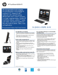
1.3 User interface in flexotempMANAGER
flexotempMANAGER is
a project setup and configuration tool
for visualization of parameters and status in form of value and graphic displays
for the following specified components.
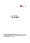
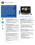
The segmentation of the user interface depends on the views to be displayed. When all views are selected, the
default user interface appears as follows.
View
Header
Symbol bar
Menu bar
Project
Selection
dependent
content
Template
Components
Data recording
Status bar
The views can be switched on and/or off by menu item <View> in the menu bar. Each view (except status bar) can
be positioned to any position on the operator interface per drag&drop.
Rev. 1.02.16
Technical changes reserved
PSG Plastic Service GmbH
Operating instructions flexotemp® Parameters
2
Parameters
In this chapter all parameters of the flexotemp® components are described.
2.1 Employed data types
Size
(Bit)
Identification
Description
Value range
8
CHAR
signed char
-128 … 127
8
BYTE
unsigned char
0 … 255
16
INT
short integer
-32,768 … 32,767
16
WORD
unsigned short integer
0 … 65,535
32
LONG
long
-2,147,483,648 … 2,147,483,647
32
ULONG
unsigned long
0 … 4,294,967,295
32
FLOAT
Single (floating-point number
with single precision)
-3,402823E38 … -1,401298E-45 for negative values;
1,401298E-45 … 3,402823E38 for positive values
2.2 Configuration and setting
With the configuration system parameters and zone parameters are distinguished between. System parameters
are zone independent for the whole controller, zone parameters are separately adjustable for each zone of the
controller.
Parameters are functionally collated in the description. The identification of a parameter is implemented over the
following
the designation/ characteristic analog of the configuration parameters as system - [SP**], zone - [P***], [CP**]
communication and/or [M***] module parameter analog the identification of the parameter in the parameter lists
of the project planning and configuration tool flexotempMANAGER
the parameter mnemonics (English), which are employed for the identification in the operating and display
units BA and in the project planning and configuration tool flexotempMANAGER
the parameter label
the data type (Bit, Byte, Char, Word, Integer) and bytes occupied by the data type
the setting range over the interfaces and over the operating and display units BA (if these are identical, the setting range is indicated only once) and a multiplication factor that is to be considered at communication by interface
a unit (when existent)
The ex-works basic setting of a parameter is identified through a bracket (e.g. [on]).
The handling of, as well as the access to, the parameters over the data interfaces (COM [serial interface PSGII, MODBUS RTU], CAN1/2 [CANopen], L2-DP [Profibus DP and DPEA],
TCP-IP Ethernet) are to be taken from the protocol descriptions, as well as from the relevant
parameter - and object lists.
The maximum setting range of a parameter is specified through its data format. In general,
the maximum possible setting range is functionally limited. This is indicated as a setting
range for the interfaces.
The detailed information on the data formats and ranges of values of the parameters are also
to be found in the object lists to the interfaces.
Rev. 1.02.16
Technical changes reserved
7
8
Chapter 2
Parameters
Between system - and zone parameters can be navigated in the window |Project| (see chapter User interface in
flexotempMANAGER). The system parameters are combined in one view. For the zone parameters exists an
overall view and predefined views, which show parts of zone parameters grouped, e.g. setpoint value, current,
configuration, etc. By <Create new zone parameter view> the operator can create his own new views at any time.
Rev. 1.02.16
Technical changes reserved
PSG Plastic Service GmbH
Operating instructions flexotemp®Parameters
2.3 System Parameters
[SP01] CELS – Temperature Unit °C/°F
Using PCU/MCU as hot runner controller, the parameter in the operation software TEMPSoft2 is named:
[SP01] Temperature Unit
Data type
Adjustment range interfaces
Adjustment range BA
Unit
Setting
Description
0 - Off
°F (unit Fahrenheit)
[1] - On
°C (unit Celsius)
Byte
0, [1]
0 - 999 °F/°C
n.a.
Unit of temperature values of all zones and configuration parameters (e.g. alarm limits).
[SP02] AMPD – Heating Current Measurement Method
Data type
Adjustment range interfaces
Adjustment range BA
Unit
Byte
0...[1]...3
0...[1]...3
n.a.
Setting
Description
0
Current measurement passive
[1]
Display of active current
[P002] OPWR – Degree of Operation > 0%: display of the currently measured current value.
[P002] OPWR – Degree of Operation <= 0%: Display 0
2
Display of current with switched on heating
[P002] OPWR – Degree of Operation > 0%: display of the currently measured current value.
[P002] OPWR – Degree of Operation > 0%: display of the last measured current value.
3
Display of current with switched off heating
Display of the measured current at [P002] OPWR – Degree of Operation = 0% (power controller defective)
Specification of measurement method and/or display mode of heating currents of all zones belonging to the controller.
A detailed description of the heating current monitoring see chapter Heating Current Measuring and Heating Current Monitoring.
Rev. 1.02.16
Technical changes reserved
9
10
Chapter
System Parameters
[SP03] MAXK – Maximum Number of Channels
Data type
Adjustment range interfaces/ multiplier
Adjustment range BA
Unit
Byte
0…[128] / 1 and/or 0...[48] / 1 and/or 0…[24] / 1
0…[128] and/or 0…[48]…128 and/or 0…[24]…128
n.a.
The parameter specifies the zone number for which the regulation is processed, starting from the first zone. The
reduction of the zone number does not have any effect on the cycle duration in case of recording of the measured
values.
[SP04] LVA1 – Release Limit Value 1
Data type
Adjustment range interfaces/ multiplier
Adjustment range BA
Unit
Integer
[0]…1999 / 10
[0]…999
°C
The release limit value defines the temperature limit, which leads to the release of all zones of one release group.
A detailed description of the group functions see chapter Group Function (Function Groups).
[SP05] LVA2 – Release Limit Value 2
Data type
Adjustment range interfaces/ multiplier
Adjustment range BA
Unit
Integer
[0]…1999 / 10
[0]…999
°C
See parameter [SP04] LVA1 – Release Limit Value 1
[SP06] LVA3 – Release Limit Value 3
Data type
Adjustment range interfaces/ multiplier
Adjustment range BA
Unit
Integer
[0]…1999 / 10
[0]…999
°C
See parameter [SP04] LVA1 – Release Limit Value 1
[SP07] LVA4 – Release Limit Value 4
Data type
Adjustment range interfaces/ multiplier
Adjustment range BA
Unit
See parameter [SP04] LVA1 – Release Limit Value 1
Rev. 1.02.16
Technical changes reserved
Integer
[0]…1999 / 10
[0]…999
°C
PSG Plastic Service GmbH
Operating instructions flexotemp®Parameters
[SP08] AGAP – Tolerance Band for Automatic Ramp
Data type
Adjustment range interfaces/ multiplier
Adjustment range BA
Unit
Byte
1…[20.0]…25.5 / 10
0…[20]…26
n.a.
Specification of the temperature tolerance band indicating how much the measured values of the zones may differ
in automatic ramp operation.
Zones, whose actual value is outside of the tolerance band, are trimmed in the output value.
A detailed description of the automatic ramp function see chapter Automatic ramp.
[SP09] IN1S – Function System Input 1,
Using PCU/MCU as hot runner controller, the parameter
[SP09] IN1S – Function System Input 1,
in the operation software TEMPSoft2 is set by Input1.
Data type
Adjustment range interfaces/ multiplier
Adjustment range BA
Unit
Byte
[0]…255 / 1
[0]…255
n.a.
Specification of the function, that the controller executes for all zones of the system, when the digital input is activated.
To use the function, at least one I/O component, with a digital input, must exist in the control system. The allocation
of digital input and the function to be executed, is done in the flexotempMANAGER for the appropriate controller
under menu item <Inputs> | <System> | <System Input 1>.
Setting
Description
[0]
Without function
1
Absolute reduction to 2. setpoint value
2
Absolute reduction to 3. setpoint value
3
Absolute reduction to 4. setpoint value
4
Relative reduction by 2. setpoint value
5
Relative reduction by 3. setpoint value
6
Relative reduction by 4. setpoint value
7
Relative increasing by 2. setpoint value
8
Relative increasing by 3. setpoint value
9
Relative increasing by 4. setpoint value
10
Percentage reduction/increasing by 2. setpoint value
11
Percentage reduction/increasing by 3. setpoint value
12
Percentage reduction/increasing by 4. setpoint value
13
Absolute reduction to 2. setpoint value, if 2SW<SW
14
Absolute reduction to 3. setpoint value, if 3SW<SW
Rev. 1.02.16
Technical changes reserved
11
12
Chapter
System Parameters
15
Absolute reduction to 4. setpoint value, if 4SW<SW
16
Disconnect actuator
17
Passivate all zones
18
Activate input block
19
Reset-acknowledge zone alarms
20
Reset-acknowledge all alarms
21
Output degree of operation of 100% for 10 sec (edge triggered)
22
Bypass group release
23
Switch to 2. control parameter set
24
Set I channel in controller to 0
25
Start timer 1
26
Start timer 2
27
Start timer 3
28
Start timer 4
29
Switch to 2. control parameter set / actual value of control = measured value 2
30
Deactivate Smart Power Limitation (SPL)
31
Activate process monitoring
32
Start learning phase of process monitoring
33
Degree of operation absolute reduction to 2. setpoint value
34
Degree of operation absolute reduction to 3. setpoint value
35
Degree of operation absolute reduction to 4. setpoint value
36
Degree of operation relative reduction by 2. setpoint value
37
Degree of operation relative reduction by 3. setpoint value
38
Degree of operation relative reduction by 4. setpoint value
39
Degree of operation relative increasing by 2. setpoint value
40
Degree of operation relative increasing by 3. setpoint value
41
Degree of operation relative increasing by 4. setpoint value
42
Cancel Heating limitation of degree of operation for zones in control mode
43
Absolute reduction by 2. setpoint value without cooling (energy saving option)
44
Relative reduction by 2. setpoint value without cooling (energy saving option)
45-128
<n.a.>
129
Absolute reduction to 2. setpoint value (inverted)
130
Absolute reduction to 3. setpoint value (inverted)
131
Absolute reduction to 4. setpoint value (inverted)
132
Relative reduction by 2. setpoint value (inverted)
133
Relative reduction by 3. setpoint value (inverted)
134
Relative reduction by 4. setpoint value (inverted)
135
Relative increasing by 2. setpoint value (inverted)
136
Relative increasing by 3. setpoint value (inverted)
137
Relative increasing by 4. setpoint value (inverted)
138
Percentage reduction/increasing by 2. setpoint value (inverted)
139
Percentage reduction/increasing by 3. setpoint value (inverted)
140
Percentage reduction/increasing by 4. setpoint value (inverted)
141
Absolute reduction to 2. setpoint value, if 2SW<SW (inverted)
Rev. 1.02.16
Technical changes reserved
PSG Plastic Service GmbH
Operating instructions flexotemp®Parameters
142
Absolute reduction to 3. setpoint value, if 3SW<SW (inverted)
143
Absolute reduction to 4. setpoint value, if 4SW<SW (inverted)
144
Disconnect actuator (inverted)
145
Passivate zone (inverted)
146
Activate input block (inverted)
147
Reset-acknowledge zone alarms (inverted)
148
Reset-acknowledge all alarms (inverted)
149
Output degree of operation of 100% for 10 sec's (inverted)
150
Bypass group release (inverted)
151
Switch to 2. control parameter set (inverted)
152
Set I channel in controller to 0 (inverted)
153
Start timer 1 (inverted)
154
Start timer 2 (inverted)
155
Start timer 3 (inverted)
156
Start timer 4 (inverted)
157
Switch to 2. control parameter set / actual value of control = measured value 2 (inverted)
158
Deactivate Smart Power Limitation (SPL) (inverted)
159
Activate process monitoring (inverted)
160
Start learning phase of process monitoring (inverted)
161
Degree of operation absolute reduction to 2. setpoint value (inverted)
162
Degree of operation absolute reduction to 3. setpoint value (inverted)
163
Degree of operation absolute reduction to 4. setpoint value (inverted)
164
Degree of operation relative reduction by 2. setpoint value (inverted)
165
Degree of operation relative reduction by 3. setpoint value (inverted)
166
Degree of operation relative reduction by 4. setpoint value (inverted)
167
Degree of operation relative increasing by 2. setpoint value (inverted)
168
Degree of operation relative increasing by 3. setpoint value (inverted)
169
Degree of operation relative increasing by 4. setpoint value (inverted)
170
Cancel Heating limitation of degree of operation for zones in control mode (inverted)
171
Absolute reduction by 2. setpoint value without cooling (energy saving option) (inverted)
172
Relative reduction by 2. setpoint value without cooling (energy saving option) (inverted)
173-255
<n.a.>
[SP10] IN2S – Function System Input 2
Using PCU/MCU as hot runner controller, the parameter
[SP10] IN2S – Function System Input 2
in the operation software TEMPSoft2 is set by Input2.
Data type
Adjustment range interfaces/ multiplier
Adjustment range BA
Unit
Byte
[0]…255 / 1
[0]…255
n.a.
Rev. 1.02.16
Technical changes reserved
13
14
Chapter
System Parameters
Specification of the function, that the controller executes for all zones of the system, when one digital input is activated.
To use the function, at least one I/O component, with a digital input, must exist in the control system. The allocation
of digital input and the function to be executed, is done in the flexotempMANAGER for the appropriate controller
under menu item <Inputs> | <System> | <System Input 2>.
See parameter [SP09] IN1S – Function System Input 1,
Rev. 1.02.16
Technical changes reserved
PSG Plastic Service GmbH
Operating instructions flexotemp®Parameters
15
Definition Byte 1 & 2 for System Alarms
[SP11] S1D1 – Definition Byte 1 – System Alarm 1
Data type
Adjustment range interfaces/ multiplier
Adjustment range BA
Unit
Byte
[0]…255 / 1
[0]…255
n.a.
The control system has 4 system alarms overall. Each system alarm is specified by 2 definition bytes. The respective first definition byte together with the appropriate second definition byte defines a filter, which alarm values lead
to an activation of a system alarm. All zones are considered for alarm calculation.
To output the status of the system alarm, at least one I/O component, with a digital output, must exist in the control
system. The allocation of digital output and system alarm, is done in the flexotempMANAGER under the I/O component with the setting <Type = Digital output> and <Definition = System alarm 1>
A detailed description of the alarm management see chapter Alarm management.
Setting
hexadecimal
decimal
Bit
0x01
1
0
Thyristor alarm (I-)
0x02
2
1
Current tolerance alarm (CTA)
0x04
4
2
LI1 (storing by LI1D)
0x08
8
3
LI2 (storing by LI2D)
0x10
16
4
LI3 (storing by LI3D)
0x20
32
5
LI4 (storing by LI4D)
0x40
64
6
LI5 (storing by LI5D)
0x80
128
7
LI6 (storing by LI6D)
Description
The setting can be combined optionally with each other. The setting value for the parameter is
decimal presented and is equivalent the sum of all setting values.
Setting value 3dec:
For thyristor alarm (I-) (0x01hex and/or 1dec) and current tolerance alarm (CTA) (0x02hex and/
or 2dec) system alarm 1 is output.
[SP12] S1D2 – Definition Byte 2 – System Alarm 1
Data type
Adjustment range interfaces/ multiplier
Adjustment range BA
Unit
Byte
[0]…255 / 1
[0]…255
n.a.
See parameter [SP11] S1D1 – Definition Byte 1 – System Alarm 1
Rev. 1.02.16
Technical changes reserved
16
Chapter
System Parameters
A detailed description of the alarm management see chapter Alarm management.
Setting
hexadecimal
decimal
Bit
Description
0x01
1
0
Sensor alarm (SAL) (always storing)
0x02
2
1
Sensor break (tCb)/sensor incorrect polarity (tCp)/ sensor 1 (not storing)
0x04
4
2
Sensor break (tCb)/sensor incorrect polarity (tCp)/ sensor 2 (not storing)
0x08
8
3
Heat sink temperature alarm
0x10
16
4
<n.a.>
0x20
32
5
Project setup or zone not started
0x40
64
6
System-/Channel data error
0x80
128
7
Error CAN / Slave error
The setting can be combined optionally with each other. The setting value for the parameter is
decimal presented and is equivalent the sum of all setting values.
Setting value 9dec:
For sensor alarm (SAL) (0x01hex and/or 1dec) and heat sink temperature alarm (0x08hex and/
or 8dec) system alarm 1 is output.
[SP13] S2D1 – Definition Byte 1 – System Alarm 2
Data type
Adjustment range interfaces/ multiplier
Adjustment range BA
Unit
Byte
[0]…255 / 1
[0]…255
n.a.
See parameter [SP11] S1D1 – Definition Byte 1 – System Alarm 1
[SP14] S2D2 – Definition Byte 2 – System Alarm 2
Data type
Adjustment range interfaces/ multiplier
Adjustment range BA
Unit
Byte
[0]…255 / 1
[0]…255
n.a.
See parameter [SP11] S1D1 – Definition Byte 1 – System Alarm 1
Rev. 1.02.16
Technical changes reserved
PSG Plastic Service GmbH
Operating instructions flexotemp®Parameters
[SP15] S3D1 – Definition Byte 1 – System Alarm 3
Data type
Adjustment range interfaces/ multiplier
Adjustment range BA
Unit
Byte
[0]…255 / 1
[0]…255
n.a.
See parameter [SP11] S1D1 – Definition Byte 1 – System Alarm 1
[SP16] S3D2 – Definition Byte 2 – System Alarm 3
Data type
Adjustment range interfaces/ multiplier
Adjustment range BA
Unit
Byte
[0]…255 / 1
[0]…255
n.a.
See parameter [SP11] S1D1 – Definition Byte 1 – System Alarm 1
[SP17] S4D1 – Definition Byte 1 – System Alarm 4
Data type
Adjustment range interfaces/ multiplier
Adjustment range BA
Unit
Byte
[0]…255 / 1
[0]…255
n.a.
See parameter [SP11] S1D1 – Definition Byte 1 – System Alarm 1
[SP18] S4D2 – Definition Byte 2 – System Alarm 4
Data type
Adjustment range interfaces/ multiplier
Adjustment range BA
Unit
Byte
[0]…255 / 1
[0]…255
n.a.
See parameter [SP11] S1D1 – Definition Byte 1 – System Alarm 1
[SP19] TRES – Timer after Reset
Data type
Adjustment range interfaces
Adjustment range BA
Unit
Byte
0...[1]...2
0...[1]...2
n.a.
A reset is caused by a sensor break, after setpoint value = 0°C/0°F or a zone passivation.
Setting
Description
0 - Run
Timer keeps on running.
[1] - Stop
Timer is stopped and reset.
Rev. 1.02.16
Technical changes reserved
17
18
Chapter
System Parameters
2 - Auto
Timer is stopped, reset and after reset started again, in case of t*d2 (see chapter View Timer)
Auto and/or A**.
A detailed description of the timer function see chapter Timer.
[SP20] ASP – Minimum Setpoint Value Change for Automatic Ramp
Data type
Adjustment range interfaces/ multiplier
Adjustment range BA
Unit
Integer
0…[20]…1000 / 10
0…[20]…999
°C
Specification of the limit, for which value at setpoint value change the automatic ramp function should be started.
For a setpoint value change less than the here set value, a setpoint value jump on the new setpoint value happens,
for a setpoint value change greater/equal the here set value, the zones, activated for the automatic ramp function,
are ramped on the new setpoint value.
Refer also to parameter [SP08] AGAP – Tolerance Band for Automatic Ramp and parameter [P018] ARMP –
Automatic Ramp.
[SP21] POT – Identification of Potential on Sensor Input
Data type
Adjustment range interfaces
Adjustment range BA
Unit
Byte
0...[1]
0...[1]
n.a.
Parameter only relevant for power controller card CANPC.
Setting
Description
0 - Off
Identification of potential switched off.
[1] - On
Identification of potential switched on.
[SP22] CMAX – Limit for Switching-off Leakage Current
Data type
Adjustment range interfaces/ multiplier
Adjustment range BA
Unit
Word
0…[300]…999 / 1
0…[300]…999
n.a.
Parameter only relevant for power controller card CANPC.
The limit value is valid per power controller card.
Rev. 1.02.16
Technical changes reserved
PSG Plastic Service GmbH
Operating instructions flexotemp®Parameters
[SP23] IN3S – Function System Input 3
Using PCU/MCU as hot runner controller, the parameter
[SP23] IN3S – Function System Input 3
in the operation software TEMPSoft2 is set by Input3.
Data type
Adjustment range interfaces/ multiplier
Adjustment range BA
Unit
Byte
[0]…255 / 1
[0]…255
n.a.
Specification of the function, that the controller executes for all zones of the system, when one digital input is activated.
To use the function, at least one I/O component, with a digital input, must exist in the control system. The allocation
of digital input and the function to be executed, is done in the flexotempMANAGER for the appropriate controller
under menu item <Inputs> | <System> | <System Input 3>.
See parameter [SP09] IN1S – Function System Input 1,.
[SP24] IN4S – Function System Input 4
Using PCU/MCU as hot runner controller, the parameter
[SP24] IN4S – Function System Input 4
in the operation software TEMPSoft2 is set by Input4.
Data type
Adjustment range interfaces/ multiplier
Adjustment range BA
Unit
Byte
[0]…255 / 1
[0]…255
n.a.
Specification of the function, that the controller executes for all zones of the system, when one digital input is activated.
To use the function, at least one I/O component, with a digital input, must exist in the control system. The allocation
of digital input and the function to be executed, is done in the flexotempMANAGER for the appropriate controller
under menu item <Inputs> | <System> | <System Input 4>.
See parameter [SP09] IN1S – Function System Input 1,.
Rev. 1.02.16
Technical changes reserved
19
20
Chapter
System Parameters
[SP25] IN5S – Function System Input 5
Using PCU/MCU as hot runner controller, the parameter
[SP25] IN5S – Function System Input 5
in the operation software TEMPSoft2 is set by Input5.
Data type
Adjustment range interfaces/ multiplier
Adjustment range BA
Unit
Byte
[0]…255 / 1
[0]…255
n.a.
Specification of the function, that the controller executes for all zones of the system, when one digital input is activated.
To use the function, at least one I/O component, with a digital input, must exist in the control system. The allocation
of digital input and the function to be executed, is done in the flexotempMANAGER for the appropriate controller
under menu item <Inputs> | <System> | <System Input 5>.
See parameter [SP09] IN1S – Function System Input 1,.
[SP26] IN6S – Function System Input 6
Using PCU/MCU as hot runner controller, the parameter
[SP26] IN6S – Function System Input 6
in the operation software TEMPSoft2 is set by Input6.
Data type
Adjustment range interfaces/ multiplier
Adjustment range BA
Unit
Byte
[0]…255 / 1
[0]…255
n.a.
Specification of the function, that the controller executes for all zones of the system, when one digital input is activated.
To use the function, at least one I/O component, with a digital input, must exist in the control system. The allocation
of digital input and the function to be executed, is done in the flexotempMANAGER for the appropriate controller
under menu item <Inputs> | <System> | <System Input 6>.
See parameter [SP09] IN1S – Function System Input 1,.
Rev. 1.02.16
Technical changes reserved
PSG Plastic Service GmbH
Operating instructions flexotemp®Parameters
[SP27] IN7S – Function System Input 7
Using PCU/MCU as hot runner controller, the parameter
[SP27] IN7S – Function System Input 7
in the operation software TEMPSoft2 is set by Input7.
Data type
Adjustment range interfaces/ multiplier
Adjustment range BA
Unit
Byte
[0]…255 / 1
[0]…255
n.a.
Specification of the function, that the controller executes for all zones of the system, when one digital input is activated.
To use the function, at least one I/O component, with a digital input, must exist in the control system. The allocation
of digital input and the function to be executed, is done in the flexotempMANAGER for the appropriate controller
under menu item <Inputs> | <System> | <System Input 7>.
See parameter [SP09] IN1S – Function System Input 1,.
[SP28] IN8S – Function System Input 8
Using PCU/MCU as hot runner controller, the parameter
[SP28] IN8S – Function System Input 8
in the operation software TEMPSoft2 is set by Input8.
Data type
Adjustment range interfaces/ multiplier
Adjustment range BA
Unit
Byte
[0]…255 / 1
[0]…255
n.a.
Specification of the function, that the controller executes for all zones of the system, when one digital input is activated.
To use the function, at least one I/O component, with a digital input, must exist in the control system. The allocation
of digital input and the function to be executed, is done in the flexotempMANAGER for the appropriate controller
under menu item <Inputs> | <System> | <System Input 8>.
See parameter [SP09] IN1S – Function System Input 1,.
Rev. 1.02.16
Technical changes reserved
21
22
Chapter
System Parameters
[SP29] COFO – Controller Overall Function Offset
Data type
Adjustment range interfaces/ multiplier
Adjustment range BA
Unit
Unsigned Integer
[0]…999 / 1
[0]…999
n.a.
Specification of a channel number independent logical zone numbering.
The parameter defines the zone number of the first zone of the controller, the zone numbers for the following zones
of the controller are consecutively. By the zone number the controller overall zone specific communication of certain functions is done.
The following functions are supported:
[P020] NrCO – Leading Zone
Together with the parameter [SP03] MAXK – Maximum Number of Channels the zone numbering can be specified very flexible.
Example
At two MCU 128 60 control channels each were used.
The zone numbering should be done consecutively from 1 to 120.
Implementation
MCU 128 #1 [SP29] COFO – Controller Overall Function Offset = 1
MCU 128 #1 [SP03] MAXK – Maximum Number of Channels = 60
MCU 128 #2 [SP29] COFO – Controller Overall Function Offset = 61
MCU 128 #2 [SP03] MAXK – Maximum Number of Channels = 60
Rev. 1.02.16
Technical changes reserved
PSG Plastic Service GmbH
Operating instructions flexotemp®Parameters
23
Definition word 3, 4, 5, 6 & 7 for system alarm 3 & 4
The parameter SD3X complements the definition of the system alarms [SP15] S3D1 – Definition Byte 1 – System
Alarm 3 and [SP16] S3D2 – Definition Byte 2 – System Alarm 3.
The parameter SD4X complements the definition of the system alarms [SP17] S4D1 – Definition Byte 1 – System
Alarm 4 and [SP18] S4D2 – Definition Byte 2 – System Alarm 4.
By the parameters, single bits/status for each zone of the existing channel flags can be output as system alarm 3
and/or 4.
For the system alarms a disjunction of all status of each single zone is done. A system alarm is generated, when
the defined bit / the defined bits are pending in a single or several zones.
The assignment of the single bits equals the assignment of the channel flags 1…10.
To output the status of the system alarm, at least one I/O component, with a digital output, must exist in the control
system. The allocation of digital output and system alarm, is done in the flexotempMANAGER under the I/O component with the setting <Type = Digital output> and <Definition = System alarm 1>.
[SP30] S3D3 – Definition Word Channel Flag 1, 2 – System Alarm 3
Data type
Adjustment range interfaces/ multiplier
Adjustment range BA
Unit
Unsigned Integer
[0]…65535 / 1
[0]…999
n.a.
A detailed description of the alarm management see chapter Alarm management.
Setting
hexadecimal
decimal
Bit
0x0001
1
0
Sensor Incorrect Polarity Sensor 2
0x0002
2
1
Sensor Break Sensor 2
0x0004
4
2
Thyristor alarm (I-)
0x0008
8
3
Current tolerance alarm (CTA)
0x0010
16
4
Temperature alarm
0x0020
32
5
Sensor Short Circuit SAL
0x0040
64
6
Sensor incorrect polarity
0x0080
128
7
Sensor break
0x0100
256
8
Limit value 1
0x0200
512
9
Limit Value 2
0x0400
1024
10
Limit value 3
0x0800
2048
11
Limit value 4
0x1000
4096
12
Limit value 5
0x2000
8192
13
Limit value 6
0x4000
16384
14
Limit Value Plus
0x8000
32768
15
Limit Value Minus
Description
The setting can be combined optionally with each other. The setting value for the parameter is
decimal presented and is equivalent the sum of all setting values.
Rev. 1.02.16
Technical changes reserved
24
Chapter
System Parameters
[SP31] S3D4 – Definition Word Channel Flag 3, 4 – System Alarm 3
Data type
Adjustment range interfaces/ multiplier
Adjustment range BA
Unit
Unsigned Integer
[0]…65535 / 1
[0]…999
n.a.
A detailed description of the alarm management see chapter Alarm management.
Setting
hexadecimal
decimal
Bit
Description
0x0001
1
0
Alarm 1
0x0002
2
1
Alarm 2
0x0004
4
2
Alarm 3
0x0008
8
3
Alarm 4
0x0010
16
4
System alarm 1
0x0020
32
5
System alarm 2
0x0040
64
6
System alarm 3
0x0080
128
7
System alarm 4
0x0100
256
8
Zone Input 1
0x0200
512
9
Zone Input 2
0x0400
1024
10
System Input 1
0x0800
2048
11
System Input 2
0x1000
4096
12
Reduction 1
0x2000
8192
13
Reduction 2
0x4000
16384
14
Software reduction 1
0x8000
32768
15
Software reduction 2
The setting can be combined optionally with each other. The setting value for the parameter is
decimal presented and is equivalent the sum of all setting values.
[SP32] S3D5 – Definition Word Channel Flag 5, 6 – System Alarm 3
Data type
Adjustment range interfaces/ multiplier
Adjustment range BA
Unit
Unsigned Integer
[0]…65535 / 1
[0]…999
n.a.
A detailed description of the alarm management see chapter Alarm management.
Rev. 1.02.16
Technical changes reserved
PSG Plastic Service GmbH
Operating instructions flexotemp®Parameters
Setting
hexadecimal
decimal
Bit
0x0001
1
0
Timer 1 active
0x0002
2
1
Timer 2 active
0x0004
4
2
Timer 3 active
0x0008
8
3
Timer 4 active
0x0010
16
4
Automatic ramp
0x0020
32
5
CAN Error Measured Value 1
0x0040
64
6
CAN Error Measured Value 2
Description
Fan alarm/heat sink temperature
The alarm here means, when an actuator module with heat sink temperature
control is configured in the system, that this module (e.g. SMA09G) outputs an
alarm, when the maximal heat sink temperature exceeds and forces a switch off
of the actuator.
0x0080
128
7
0x0100
256
8
Setpoint value reached
0x0200
512
9
Identification Heating
0x0400
1024
10
Identification Cooling
0x0800
2048
11
Manual temperature ramp active
0x1000
4096
12
Actuator deactivated
0x2000
8192
13
Actuator deactivated by limit value
0x4000
16384
14
2. Control parameter set
0x8000
32768
15
Leading zone active
The setting can be combined optionally with each other. The setting value for the parameter is
decimal presented and is equivalent the sum of all setting values.
[SP33] S3D6 – Definition Word Channel Flag 7, 8 – System Alarm 3
Data type
Adjustment range interfaces/ multiplier
Adjustment range BA
Unit
Unsigned Integer
[0]…65535 / 1
[0]…999
n.a.
A detailed description of the alarm management see chapter Alarm management.
Setting
hexadecimal
decimal
Bit
0x0001
1
0
Group Release
0x0002
2
1
Group wide reduction
0x0004
4
2
Error in configuration table CANCT
Description
Rev. 1.02.16
Technical changes reserved
25
26
Chapter
System Parameters
Slave interface error CANCT
0x0008
8
3
By this bit an error on the RS485 interface below the CANCT or a BACI is signalized. Is below the CANCT e.g. a SMA09 configured and this module is not
recognized, in this bit an error is signalizes.
0x0010
16
4
Smart Power Limitation (SPL) inactive
0x0020
32
5
Start-up mode by timer
0x0040
64
6
Zone passive
Zone in control mode
0x0080
128
7
0x0100
256
8
0x0200
512
9
System data error
Check sum/EEPROM error of system parameters.
Channel data error
Check sum/EEPROM error of channel parameters.
Leakage current error CANPC
0x0400
1024
10
CANPC is a power controller card that monitors the residual current by a current
transformer. A maximum permissible limit (in mA) for the residual current can be
adjusted on this controller card. Is the limit exceeded, an error is signalized. Is
no CANPC configured, this error is not signalized.
Potential error CANTC
0x0800
2048
11
CANTC is a card in the rack system to register the temperatures of thermocouples. This module detects when a too high potential on a sensor input (e.g. a
mains phase is connected to the sensor input). In this case an potential error is
signalized. Is no CANTC configured, this error is not signalized.
Phase error CANPC
CANPC is a power controller card, that detects, the mains phases are connected. Is a mains phase missing, an error is signalized. Is no CANPC configured,
this error is not signalized.
0x1000
4096
12
0x2000
8192
13
CANPC is a power controller card, that detects, a too big load and/or the existence of a short circuit. Is no CANPC configured, this error is not signalized.
0x4000
16384
14
Limit value band at startup operation o.k.
0x8000
32768
15
IKMAX error CANPC
Error CANPC
This bit signalizes an error when a configured CANPC power controller card is
missing. Is no configured, this bit is not set.
The setting can be combined optionally with each other. The setting value for the parameter is
decimal presented and is equivalent the sum of all setting values.
[SP34] S3D7 – Definition Word Channel Flag 9, 10 – System Alarm 3
Data type
Adjustment range interfaces/ multiplier
Adjustment range BA
Unit
Unsigned Integer
[0]…65535 / 1
[0]…999
n.a.
A detailed description of the alarm management see chapter Alarm management.
Rev. 1.02.16
Technical changes reserved
PSG Plastic Service GmbH
Operating instructions flexotemp®Parameters
Setting
hexadecimal
decimal
Bit
0x0001
1
0
Identification Heating o.k.
0x0002
2
1
Identification Cooling o.k.
0x0004
4
2
System Input 3
0x0008
8
3
System Input 4
0x0010
16
4
System Input 5
0x0020
32
5
System Input 6
0x0040
64
6
System Input 7
0x0080
128
7
System Input 8
Description
Heat sink temperature limit value
For each CANCT or BACI a heat sink temperature limit value can be set. All
modules below CANCT/BACI, which measure a heat sink temperature, report
this to CANCT/BACI. Is the set limit value exceeded, an error is signalized and
written into the corresponding control channel.
0x0100
256
8
0x0200
512
9
Fuse defective HPC (on Heating Power Card)
0x0400
1024
10
Phase error HPC (on Heating Power Card)
0x0800
2048
11
Without function
0x1000
4096
12
Without function
0x2000
8192
13
Without function
0x4000
16384
14
Without function
0x8000
32768
15
Without function
The setting can be combined optionally with each other. The setting value for the parameter is
decimal presented and is equivalent the sum of all setting values.
[SP35] S4D3 – Definition Word Channel Flag 1, 2 – System Alarm 4
Data type
Adjustment range interfaces/ multiplier
Adjustment range BA
Unit
Unsigned Integer
[0]…65535 / 1
[0]…999
n.a.
See parameter [SP30] S3D3 – Definition Word Channel Flag 1, 2 – System Alarm 3
[SP36] S4D4 – Definition Word Channel Flag 3, 4 – System Alarm 4
Data type
Adjustment range interfaces/ multiplier
Adjustment range BA
Unit
Unsigned Integer
[0]…65535 / 1
[0]…999
n.a.
See parameter [SP31] S3D4 – Definition Word Channel Flag 3, 4 – System Alarm 3
Rev. 1.02.16
Technical changes reserved
27
28
Chapter
System Parameters
[SP37] S4D5 – Definition Word Channel Flag 5, 6 – System Alarm 4
Data type
Adjustment range interfaces/ multiplier
Adjustment range BA
Unit
Unsigned Integer
[0]…65535 / 1
[0]…999
n.a.
See parameter [SP32] S3D5 – Definition Word Channel Flag 5, 6 – System Alarm 3
[SP38] S4D6 – Definition Word Channel Flag 7, 8 – System Alarm 4
Data type
Adjustment range interfaces/ multiplier
Adjustment range BA
Unit
Unsigned Integer
[0]…65535 / 1
[0]…999
n.a.
See parameter [SP33] S3D6 – Definition Word Channel Flag 7, 8 – System Alarm 3
[SP39] S4D7 – Definition Word Channel Flag 9, 10 – System Alarm 4
Data type
Adjustment range interfaces/ multiplier
Adjustment range BA
Unit
Unsigned Integer
[0]…65535 / 1
[0]…999
n.a.
See parameter [SP34] S3D7 – Definition Word Channel Flag 9, 10 – System Alarm 3
[SP40] PMOD – Process Monitoring Mode
Data type
Adjustment range interfaces/ multiplier
Adjustment range BA
Unit
Setting
Byte
[0]…3 / 1
[0]…3
n.a.
Description
[0]
passive
1
Fully-automatic
Process monitoring starts automatically following the automatic started
learning phase with the set values for [P097] PTOL – Tolerance of
Process.
2
Manual
Process monitoring starts automatically following the manual started
learning phase with the set values for [P097] PTOL – Tolerance of
Process.
Intelligent
Process monitoring starts automatically following the manual started
learning phase with the calculated values during learning phase for
[P097] PTOL – Tolerance of Process. The determined value for
[P099] POP – Operating point of process monitoring during learning
phase is stored.
3
Rev. 1.02.16
Technical changes reserved
Function is deactivated.
PSG Plastic Service GmbH
Operating instructions flexotemp®Parameters
A detailed description of the function see chapter Process Monitoring.
[SP48] S1Dt - System Alarm 1 Delay Time
Data type
Adjustment range interfaces/ multiplier
Adjustment range BA
Unit
Byte
[0]…255 / 1
[0]…255
s
The corresponding system alarm is delayed by the time set here. Is the reason for the alarm already gone, no
system alarm is generated.
[SP49] S2Dt - System Alarm 2 Delay Time
Data type
Adjustment range interfaces/ multiplier
Adjustment range BA
Unit
Byte
[0]…255 / 1
[0]…255
s
See parameter [SP48] S1Dt - System Alarm 1 Delay Time
[SP50] S3Dt - System Alarm 3 Delay Time
Data type
Adjustment range interfaces/ multiplier
Adjustment range BA
Unit
Byte
[0]…255 / 1
[0]…255
s
See parameter [SP48] S1Dt - System Alarm 1 Delay Time
[SP51] S4Dt - System Alarm 4 Delay Time
Data type
Adjustment range interfaces/ multiplier
Adjustment range BA
Unit
Byte
[0]…255 / 1
[0]…255
s
See parameter [SP48] S1Dt - System Alarm 1 Delay Time
Rev. 1.02.16
Technical changes reserved
29
30
Chapter
Time Server
2.4 Time Server
The time server, a PC equipped with the Network Time Protocol, where the project setup - and configuration tool
flexotempMANAGER is running, provides the clients (master components MCU, PCU) with the current time stamp
on request. Thus the master components are synchronized.
The function is supported by the master components (MCU, PCU) from software version
…0910A.
All necessary settings for the time server can be done by BA as well.
Also official time servers are supported, when there IP address specified.
[SP41] tS – Time Synchronization
Data type
Adjustment range interfaces
Adjustment range BA
Unit
Setting
Description
[0] - Off
Function is deactivated.
1 - On
Function is activated.
Byte
[0], 1
[0]…1
n.a.
[SP42] tS1 – IP Address 1. Octet
Data type
Adjustment range interfaces/ multiplier
Adjustment range BA
Unit
Unsigned Char
[0]…255 / 1
[0]…255
n.a.
1. Octet of IP address of time server (XXX.***.***.***).
[SP43] tS2 – IP Address 2. Octet
Data type
Adjustment range interfaces/ multiplier
Adjustment range BA
Unit
2. Octet of IP address of time server (***.XXX.***.***).
Rev. 1.02.16
Technical changes reserved
Unsigned Char
[0]…255 / 1
[0]…255
n.a.
PSG Plastic Service GmbH
Operating instructions flexotemp®Parameters
[SP44] tS3 – IP Address 3. Octet
Data type
Adjustment range interfaces/ multiplier
Adjustment range BA
Unit
Unsigned Char
[0]…255 / 1
[0]…255
n.a.
3. Octet of IP address of time server (***.***.XXX.***).
[SP45] tS4 – IP Address 4. Octet
Data type
Adjustment range interfaces/ multiplier
Adjustment range BA
Unit
Unsigned Char
[0]…255 / 1
[0]…255
n.a.
4. Octet of IP address of time server (***.***.***.XXX).
[SP46] tSMt – Time Zone
Word
(GMT-12:00) International dateline (West)
…
[(GMT+01:00) Amsterdam, Berlin, Bern, Stockholm, Vienna)]
…
(GMT+12:00) Fiji, Kamchatka, Marshall Islands
Adjustment range BA
[0]…91
Unit
n.a.
Data type
Adjustment range interfaces
The setting and display of the time zone, which is used for time synchronization of the master components, is done
by this parameter. For further processing the parameter [SP47] tSTz – Time Zone (internal) is used and derived
from this parameter.
[SP47] tSTz – Time Zone (internal)
The parameter is not displayed in flexotempMANAGER.
Data type
Adjustment range interfaces
Adjustment range BA
Unit
Char
-127…[0]…127
[0]…127
0.25 h (15 minutes)
A communication with the master components read/write is done by parameter [SP47] tSTz – Time Zone (internal). For plain text display the content of the parameter [SP47] tSTz – Time Zone (internal) is converted to parameter [SP46] tSMt – Time Zone and displayed in flexotempMANAGER.
Rev. 1.02.16
Technical changes reserved
31
32
Chapter
Time Server
The parameter [SP47] tSTz – Time Zone (internal) presents always the value, that is/will be stored in the master
component. For discrepancies between the content of parameter [SP46] and [SP47], the value of [SP47] is used
and tried to be displayed for [SP46].
In case no valid value can be determined out of the list of value for parameter [SP46], it shows:
(GMT<Value parameter [SP47]) invalid time zone
Rev. 1.02.16
Technical changes reserved
PSG Plastic Service GmbH
Operating instructions flexotemp® Parameters
33
2.5 Zone Parameters
In the window |Project| below the component under <Zone parameter> all zone parameters are listed consecutively with their parameter label / characteristic analog.
For the zone parameters exist predefined (standard) views, where the zone parameters are functionally and/or
application specific grouped displayed.
For clarity, the zone parameters of the single available standard views are described.
2.5.1 View Setpoint Value
In this view all zone parameters are concentrated, concerning settings for setpoint values.
[P001] SP – Setpoint Value
Data type
Adjustment range interfaces/ multiplier
Adjustment range BA
Unit
Integer
-30.0…[0.0]…1999.0 / 10
-30...[0]…999
°C
Main setpoint value on which control is implemented when 2., 3. or 4. setpoint value not active.
With setpoint value 0°C/≤32°F, the zone is passivated and the control algorithm is reinitialized.
With active manual mode, the setpoint value is without function.
[P009] SP2 – 2. Setpoint / 2. Lowering/Reduction Value
Using PCU/MCU as hot runner controller, the parameter in the operation software TEMPSoft2 is named:
[P009] Standby setpoint
Data type
Adjustment range interfaces/ multiplier
Adjustment range BA
Unit
Integer
[0.0]…1999.0 / 10
[0]…999
°C
The second setpoint value and/or second lowering/reduction value is activated by a digital input.
Depending on the function definition of the digital input, it is activated system wide, group dependent or zone specific. By the definition is also specified, whether the setpoint value acts as absolute value or as setpoint value increase/ -reduction.
See also:
Parameter [SP09] IN1S – Function System Input 1, ff.
Parameter [SP082] IN1C – Function Zone Input 1 ff.
Parameters[P084] GPIN – Input Group
Rev. 1.02.16
Technical changes reserved
34
Chapter
Zone Parameters
[P010] SP3 – 3. Setpoint / 3. Lowering/Reduction Value
Using PCU/MCU as hot runner controller, the parameter in the operation software TEMPSoft2 is named:
[P010] Boost setpoint
Data type
Adjustment range interfaces/ multiplier
Adjustment range BA
Unit
Integer
[0.0]…1999.0 / 10
[0]…999
°C
The third setpoint value and/or third lowering/reduction value is activated by a digital input.
Depending on the function definition of the digital input, it is activated system wide, group dependent or zone specific. By the definition is also specified, whether the setpoint value acts as absolute value or as setpoint value increase/ -reduction.
See also:
Parameter [SP09] IN1S – Function System Input 1, ff.
Parameter [SP082] IN1C – Function Zone Input 1 ff.
Parameters[P084] GPIN – Input Group
[P011] SP4 – 4. Setpoint / 4. Lowering/Reduction Value
Data type
Adjustment range interfaces/ multiplier
Adjustment range BA
Unit
Integer
[0.0]…1999.0 / 10
[0]…999
°C
The fourth setpoint value and/or fourth lowering/reduction value is activated by a digital input.
Depending on the function definition of the digital input, it is activated system wide, group dependent or zone specific. By the definition is also specified, whether the setpoint value acts as absolute value or as setpoint value increase/ -reduction.
See also:
Parameter [SP09] IN1S – Function System Input 1, ff.
Parameter [SP082] IN1C – Function Zone Input 1 ff.
Parameters[P084] GPIN – Input Group
[P012] SPLO – Lower Setpoint Value Limit
Data type
Adjustment range interfaces/ multiplier
Adjustment range BA
Unit
Integer
-30.0…[0.0]…1999.0 / 10
-30...[0]…999
°C
Lower input limitation for all temperature setpoints. The value should be adjusted dependent on the measurement
range of the used thermocouple TC/ resistance thermometer Pt100.
Rev. 1.02.16
Technical changes reserved
PSG Plastic Service GmbH
Operating instructions flexotemp® Parameters
[P013] SPHI – Upper Setpoint Value Limit
Data type
Adjustment range interfaces/ multiplier
Adjustment range BA
Unit
Integer
-30.0…[0.0]…1999.0 / 10
-30...[0]…999
°C
Upper input limitation for all temperature setpoints. The value should be adjusted dependent on the measurement
range of the used thermocouple TC/ resistance thermometer Pt100.
Rev. 1.02.16
Technical changes reserved
35
36
Chapter
Zone Parameters
2.5.2 View Current
In this view all zone parameters are concentrated, concerning settings for heating current.
[P004] CurS – Current Setpoint Value
Data type
Adjustment range interfaces/ multiplier
Adjustment range BA
Unit
Word
[0.0]…999.0 / 10
[0.0]…99.9
A
Current value, where the measured heating current is compared with.
Input of the value manual or by automatic current transfer.
A current alarm is generated, when the measured heating current is outside the current tolerance band around the
current setpoint value.
[P005] CurT – Current Tolerance
Data type
Adjustment range interfaces/ multiplier
Adjustment range BA
Unit
Word
0.0…[20.0]…100.0 / 10
0…[20.0]…99.9
%
Current tolerance band around the [P004] CurS – Current Setpoint Value for monitoring of heating current.
[P005] CurT – Current Tolerance is limitated below as follows.
[P005] CurT – Current Tolerance * [P004] CurS – Current Setpoint Valuecurrent setpoint value [A] must be
greater than 0.5 A.
The minimal current tolerance value is therefore dependent on the current setpoint value.
Please note, that [P005] CurT – Current Tolerance is always sufficiently dimensioned, so that
current changes caused by voltage fluctuations do not cause "false alarms".
Rev. 1.02.16
Technical changes reserved
PSG Plastic Service GmbH
Operating instructions flexotemp® Parameters
37
2.5.3 View Configuration
In this view all zone parameters are concentrated, concerning settings for configuration.
[P006] ZONE – Zone
Data type
Adjustment range interfaces
Adjustment range BA
Unit
Bit
0, [1]
off, [on]
n.a.
Setting
Description
0 - Off
At control outputs no actuating signals are output.
No alarms are calculated.
[1] - On
At the control output in accordance with operating mode (control/manual mode) actuating signals
are output. All alarms are calculated.
[P007] ZTYP – Type of Zone
Data type
Adjustment range interfaces
Adjustment range BA
Unit
Setting
Description
[0]
Zone in control mode (Ctr)
1
Zone in measuring mode (MSR)
2
Additional zone
Byte
[0]...2
[Ctr], MSR
n.a.
For zone in measuring mode no degree of operation is output.
Additional zones are control zones in the hot runner controller, which are functional not equate to the zones of the
hot runner controller, that means that they are not considered at hot runner controller functions like startup operation, Standby, Boost etc. The additional zones may for example be used to control the temperature of the control
cabinet or to control a water/oil temperate device.
Additional zones are specified by parameter [P007] ZTYP – Type of Zone as additional zones, starting from the
last zone sequential. As soon as a gap is detected (zone not marked as additional zone), all further zones marked
as additional are refused.
Use of PCU048
Parameter [SP03] MAXK – Maximum Number of Channels = 48
For zone 48, zone 47, zone 45: parameter [P007] ZTYP – Type of Zone = 2
Determination of zones for hot runner control =46
Determination of additional zones = 2
(Explanation: starting from the last zone (48), zone 48 and zone 47 are sequential and stated
as additional zones. Zone 46 is no additional zone and the determination is terminated, with
the result 2 additional zones)
Rev. 1.02.16
Technical changes reserved
Chapter
Zone Parameters
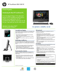
[P008] SEnC – Actual Value of Control
Byte
[0]…5 / 1
[0]…5
n.a.
Data type
Adjustment range interfaces/ multiplier
Adjustment range BA
Unit
Setting
Description
[0]
Measured value 1
1
Measured value 2
2
Measured value 1- measured value 2
3
Measured value1=actual value of control / measured value2 = Max. Temp. Alarm
4
Measured value1=actual value of control / measured value2 = Max. Temp. Alarm + limit value
5
(Measured value 1 + measured value 2) /2
Master component
[P100]
Analog inputs
38
Measured value 1
Measured value 2
Actual value 1
Actual value of
control
Actual value 2
[P101]
[P008]
internal
See parameter [P100] OFF1 – Temperature offset actual value 1
See parameter [P101] OFF2 – Temperature offset actual value 2
[P022] APPL – Application
Data type
Adjustment range interfaces/ multiplier
Adjustment range BA
Unit
Byte
[0]…255 / 1
[0]…255
n.a.
By means of the parameter, extended customer-specific functions or adaptations to pre-determined applications
can be connected to the standard functions.
Rev. 1.02.16
Technical changes reserved
PSG Plastic Service GmbH
Operating instructions flexotemp® Parameters
Setting
Description
11
Passive automatic ramp
Activated and [P018] ARMP – Automatic Ramp = 1, the zone, in automatic ramp mode, is
heated up, but is not considered as slowest zone (= reference zone).
The function is canceled, when there is no more reference zone available.
12
Activated and [P018] ARMP – Automatic Ramp = 1, then this zone must not be leading in
automatic ramp mode, and no cooling degree of operation is output.
13
Activated and [P018] ARMP – Automatic Ramp = 1, then this zone must not output a cooling
degree of operation.
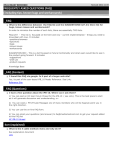
[P023] OUTH – Heating Degree of Operation Damping
Char
0…[100] / 1
0…[100]
%
Data type
Adjustment range interfaces/ multiplier
Adjustment range BA
Unit
The parameter has 2 functions. It defines,
whether the control module Heating is used for the zone
whether the Heating degree of operation is output damped.
Setting
Description
=0
The control module Heating is not used.
>0
The control module Heating is used.
Definition for correction of the Heating degree of operation:
Corrected degree of operation = degree of operation x 0.01 x setting
value
Setting value OUTH = 75
Uncorrected degree of operation = 85%
Over the complete range of
degree of operation, a reduced, corrected degree of operation is output.
Effective
output
degree of operation
Corrected degree of operation = 85% x 0.01 x 75 = 63%
(rounded)
100
OUTH = 100
OUTH = 50
OUTH = 25
0/0
100 degree of operation
Rev. 1.02.16
Technical changes reserved
39
40
Chapter
Zone Parameters
[P024] OUTC – Cooling Degree of Operation Damping
Standard
Only PCU***HA
Data type
Char
Char
Adjustment range interfaces/ multiplier
[-100]…0 / 1
-100…[0] / 1
Adjustment range BA
[-100]…0
-100...[0]
Unit
%
%
The parameter has 2 functions. It defines,
whether the control module Cooling is used for the zone
whether the Cooling degree of operation is output damped.
Setting
Description
=0
The control module Cooling is not used.
>0
The control module Cooling is used.
Definition for correction of the Cooling degree of operation:
Corrected degree of operation = degree of operation x 0.01 x setting
value
Setting value OUTC = 75
Uncorrected degree of operation = -40%
Corrected degree of operation = -40% x 0.01 x |-75| = 30%
(rounded)
[P026] RELH – Heating Relay Output
Data type
Adjustment range interfaces
Adjustment range BA
Unit
Bit
[0]…1
[off], on
n.a.
Specifies the manner in which the actuating signal is output at the Heating control output.
Through this, an adaptation of the actuating signal to the actuator (SSR, relay) is possible.
Setting
Description
[0] - Off
Output of the actuating variable through fast clocked pulse groups (e.g. for the output to solid
state relay). The minimum pulse width is 40 ms.
1 - On
Output of the actuating variable through fast clocked pulse groups (e.g. for the output to solid
state relay). The minimum pulse width is 40 ms.
The [P045] CTH – Heating Sampling Time and [P053] CTH2 - Heating Sampling Time 2 are
minimum 10 seconds.
A detailed description of the control output signals see chapter Control output signals.
Rev. 1.02.16
Technical changes reserved
PSG Plastic Service GmbH
Operating instructions flexotemp® Parameters
[P027] RELC – Cooling Relay Output
Data type
Adjustment range interfaces
Adjustment range BA
Unit
Bit
0…[1]
off, [on]
n.a.
Specifies the manner in which the actuating signal is output at the Cooling control output.
Through this, an adaptation of the actuating signal to the actuator (SSR, relay) is possible.
Setting
Description
0 - Off
Output of the actuating variable through fast clocked pulse groups (e.g. for the output to solid
state relay). The minimum pulse width is 40 ms.
[1] - On
Output method is suitable for operation of mechanical relays as actuators.
Per sampling cycle (corresponds to sampling time) the actuating variable Cooling is output in the
block (one-time switching on and off of the setting output). The operating time is proportional to
the degree of operation with reference to the sampling time.
The [P049] CTC – Cooling Sampling Time and [P057] CTC2 – Cooling Sampling Time 2 are
minimum 10 seconds.
A detailed description of the control output signals see chapter Control output signals.
[P028] PCLG – Pulse Cooling
Data type
Adjustment range interfaces
Adjustment range BA
Unit
Bit
[0]…1
[off], on
n.a.
Setting
Description
[0] - Off
Conventional output percentage output
A PWM signal, proportional to the degree of operation, is output at the Cooling control output.
Refer also to parameter [P027] RELC – Cooling Relay Output.
1 - On
In case of the pulse cooling (also: impulse cooling), the pulse duration is constant at the Cooling
control output and the pause duration (between 2 impulses) is variable. The degree of operation
is generated by the variable pause between to the constant pulses.
The pause length is limited by the parameter [P030] PMIN – Minimum Pause Duration and
[P031] PMAX – Maximum Pause Duration . The mandatory pause adjustable through the parameter [P030] PMIN – Minimum Pause Duration and should prevent the transition from evaporating to continuous water flow. PMIN should correspond to a cooling pulse in about the reaction
time of the route sections.
Changes of the degree of operation are incorporated only on completion of the current pulse separation.
The relationship between pulse width and maximum pause duration determines the real degree
of operation resolution. For a one-percent degree of operation resolution [P031] PMAX – Maximum Pause Duration at least the hundred-fold time value of [P029] PULS – Pulse Duration is
to be to set adjusted (please be sure to consider the different units of the parameters).
Rev. 1.02.16
Technical changes reserved
41
42
Chapter
Zone Parameters
Prerequisite for the pulse cooling is that [P024] OUTC – Cooling Degree of Operation Damping is set to -100.
A detailed description of the control output signals see chapter Control output signals.
[P029] PULS – Pulse Duration
Data type
Adjustment range interfaces/ multiplier
Adjustment range BA
Unit
Word
4…[20]…500 / 1
4…[20]…500
10 ms
Defines the duration of an impulse at the control output Cooling in case of active [P028] PCLG – Pulse Cooling.
Be sure to consider that the pulse duration is 10x the setting value.
The setting value should
be long enough so that the actuator (e.g. solenoid valve) can act properly
be large enough to determine a change of the actual value.
The setting value should be selected so, that the actual value changes with an individual pulse only insignificantly.
In case of changes of the parameters of the pulse cooling, it is absolutely necessary that the
control parameters be adapted to cooling.
A detailed description of the control output signals see chapter Control output signals.
[P030] PMIN – Minimum Pause Duration
Data type
Adjustment range interfaces/ multiplier
Adjustment range BA
Unit
Word
0.0…[50.0]…999.0 / 1
0.0…[50.0]…999.0
s
Minimum duration between two pulses in case of active [P028] PCLG – Pulse Cooling
A detailed description of the control output signals see chapter Control output signals.
Rev. 1.02.16
Technical changes reserved
PSG Plastic Service GmbH
Operating instructions flexotemp® Parameters
[P031] PMAX – Maximum Pause Duration
Data type
Adjustment range interfaces/ multiplier
Adjustment range BA
Unit
Word
0.0…[200.0]…999.0 / 1
0.0…[50.0]…999.0
s
Maximum duration between two pulses in case of active [P028] PCLG – Pulse Cooling
A detailed description of the control output signals see chapter Control output signals.
[P100] OFF1 – Temperature offset actual value 1
Data type
Adjustment range interfaces/ multiplier
Unit
Word
-99.9…[0.0]…99.0 / 10
K
The actual value 1 is corrected as follows:
Corrected actual value 1 = actual value 1 + temperature offset actual value 1
From HEX file version xx4310
[P101] OFF2 – Temperature offset actual value 2
Data type
Adjustment range interfaces/ multiplier
Unit
Word
-99.9…[0.0]…99.0 / 10
K
The actual value 1 is corrected as follows:
Corrected actual value 2 = actual value 1 + temperature offset actual value 2
From HEX file version xx4310
Rev. 1.02.16
Technical changes reserved
43
44
Chapter
Zone Parameters
2.5.4 View Control Parameters
In this view all zone parameters are concentrated, concerning settings for control.
A detailed description about all around the theme calculation of control parameters see chapter
Auto Tuning (Identification).
[P032] IDEH – Heating Identification
Using PCU/MCU as hot runner controller, the parameter in the operation software TEMPSoft2 is named:
[P032] Identification
Standard
Only PCU***HA
Data type
Bit
Bit
Adjustment range interfaces
0…[1]
[0]…1
Adjustment range BA
off, [on]
off, [on]
Unit
n.a.
n.a.
Setting
Description
0 - Off
The controller controls with the fix adjusted control parameter set Heating. At no phase are the
control parameters Heating newly calculated.
1 - On
After a zone reset, i.e.
controller is switched on
zone was passivated and is activated
setpoint value less than or equal to 0°C / 32 K
the Heating control parameters, for the active control parameter set, are calculated automatically
during the first setpoint value increase greater than 45 K while heating-up.
[P033] IDEL – Loop Control in Case of Identification
Using PCU/MCU as hot runner controller, the parameter in the operation software TEMPSoft2 is named:
[P033] Loop control
Data type
Adjustment range interfaces
Adjustment range BA
Unit
Setting
Description
0 - Off
Function is deactivated.
Rev. 1.02.16
Technical changes reserved
Bit
0…[1]
off, [on]
n.a.
PSG Plastic Service GmbH
Operating instructions flexotemp® Parameters
[1] - On
During the identification phase Heating, shortly before reaching the setpoint value, the control
characteristic is considered and if necessary a correction of the control parameters Heating of
the active control parameter set is made.
[P034] IDCH – Cooling Identification after Heating Identification
Bit
[0]…1
[off], on
n.a.
Data type
Adjustment range interfaces
Adjustment range BA
Unit
Setting
Description
[0] - Off
After the sequence identification Heating no identification Cooling is executed.
1 - On
The control parameters Cooling of the active control parameter set are determined automatically
direct after completion of the [P032] IDEH – Heating Identification.
Therefore the lowest degree of operation (according to the setting [P024] OUTC – Cooling Degree of Operation Damping) is output and the control parameter Cooling is calculated according
to the actual value trend.
After end of the calculation of the control parameters, the active setting value is controlled again.
The function only operates for [P024] OUTC – Cooling Degree of Operation Damping < 0.
[P035] SPCb – Setpoint Value Cutback
Using PCU/MCU as hot runner controller, the parameter in the operation software TEMPSoft2 is named:
[P035] Cutback
Data type
Adjustment range interfaces/ multiplier
Adjustment range BA
Unit
Byte
[0]…200 / 1
[0]…200
n.a.
The setpoint value cutback function is used to prevent an overshooting during identification phase. Therefore the
calculation of the control parameters Heating of the active control parameter set is executed on a temperature setpoint value reduced by the setpoint value cutback. After determination and verification of the control parameters,
it is immediately controlled on the final setpoint value.
The function only operates for the setting [P033] IDEL – Loop Control in Case of Identification
= On.
Rev. 1.02.16
Technical changes reserved
45
46
Chapter
Zone Parameters
[P036] CFIX – Cooling Parameter fixed (Heating Identification)
Data type
Adjustment range interfaces/ multiplier
Adjustment range BA
Unit
Bit
[0]…1
[off], on
n.a.
In case the dimension of heating and cooling power for the zone matches, in general the control parameters Cooling could be deduced from the control parameters Heating.
Setting
Description
[0] - Off
The control parameters Cooling of the active control parameter set are recalculated for identification heating without carrying out an adaptation Cooling. Basis for the control parameters Cooling are the control parameters Heating.
1 - On
The control parameters Cooling are not modified through a Heating identification.
[P037] IDEC – Cooling Identification
Data type
Adjustment range interfaces/ multiplier
Adjustment range BA
Unit
Bit
0…[1]
off, [on]
n.a.
Setting
Description
0 - Off
At no phase are the control parameters Cooling newly calculated.
[1] - On
At a setpoint value jump > -30K the control parameters Cooling of the active control parameter
set are determined automatically.
The function only operates for [P024] OUTC – Cooling Degree of Operation Damping < 0.
[P038] ALGO – Algorithm
Data type
Adjustment range interfaces/ multiplier
Adjustment range BA
Unit
Bit
[0]…255 / 1
[0]…255
n.a.
Specification, which control algorithm is used for control.
Setting
Description
[0]
Standard - dynamic control algorithm for temperature zones
1
Standard slow
2
Standard slower
3
Standard quick
4
Standard quicker
Rev. 1.02.16
Technical changes reserved
PSG Plastic Service GmbH
Operating instructions flexotemp® Parameters
10
Customer specific DB
16
Main controller cascade
17
Auxiliary controller cascade
32
Simple PID
128
Standard without correction of operating point shift
129
Standard slow without correction of operating point shift
130
Standard slower without correction of operating point shift
131
Standard quick without correction of operating point shift
132
Standard quicker without correction of operating point shift
Information on "correction of operating point shift"
The control algorithm can identify a changing operating point of a zone. That means for example the starting and/or shutdown of a plant or for extruders the increase of the RPM to increase
the capacity.
Additional to control the controller supervises the operating point as standard and corrects by
interaction of output value. In some applications these interaction are not wanted. Therefore
the control can work without correction of operating point shift.
[P039] KNr – Cascade - Zone Number of Main Controller
Data type
Adjustment range interfaces/ multiplier
Adjustment range BA
Unit
Byte
[0]…128 / 1
[0]…128
n.a.
Detailed information on cascade control see chapter Cascade Control.
[P040] KSP- – Cascade - Setpoint Value of Auxiliary Controller for Degree of Operation =0/-100%
Data type
Adjustment range interfaces/ multiplier
Adjustment range BA
Unit
Integer
-1000…[0]…1000 / 1
-1000…[0]…1000
n.a.
Detailed information on cascade control see chapter Cascade Control.
Rev. 1.02.16
Technical changes reserved
47
48
Chapter
Zone Parameters
[P041] KSP+ – Cascade - Setpoint Value of Auxiliary Controller for Degree of Operation = 100%
Data type
Adjustment range interfaces/ multiplier
Adjustment range BA
Unit
Integer
-1000…[0]…1000 / 1
-1000…[0]…1000
n.a.
Detailed information on cascade control see chapter Cascade Control.
[P042] XPH – Heating Proportional Band
Using PCU/MCU as hot runner controller, the parameter in the operation software TEMPSoft2 is named:
[P042] Proportional band
Data type
Adjustment range interfaces/ multiplier
Adjustment range BA
Unit
Word
0.0…[9.9]…250.0 / 10
[0]…250.0
%
The P content changes the output of the PID controller proportional to the deviation between setpoint and actual
value.
The proportional band is the range of the process variable, in which this linear reinforcement occurs before the
output achieves its maximum or minimum. This range is indicated in percent of the measuring range. In order that
the adjusted proportional band is independent of the sensor type and/or measuring range, the controller measuring range in case of PSG controllers is assumed at 500°C (1% corresponds to 5 K).
The amplification of the controller decreases with increasing proportional band, and increases with decreasing
proportional band. In case of a proportional band selected too small, the controller reacts to small deviations so
severely that the control system oscillates. On the other hand, a proportional band which is selected too large
makes the regulation very slow. The controller no longer reacts adequately to faults.
In case of utilization of pure proportional band controllers in the control system, the deviation cannot be eliminated
fully. There results the so-called permanent deviation.
[P043] TDH – Heating Derivative Time
Using PCU/MCU as hot runner controller, the parameter in the operation software TEMPSoft2 is named:
[P043] Derivative time
Data type
Adjustment range interfaces/ multiplier
Adjustment range BA
Unit
Word
0…[255]…65535 / 1
[0]…999
s
The differential content (D content) of the PID controller reacts in a leading way to the rate of change of the deviation or the actual value.
Rev. 1.02.16
Technical changes reserved
PSG Plastic Service GmbH
Operating instructions flexotemp® Parameters
The differential content then supplies only a actuating variable, if the deviation or the actual value is changed.
Therefore it cannot be used in order to stabilize a constant control deviation. That also explains the utilization of
the D regulator only in association with P or PI characteristic.
The importance of the differential content in practice lies in the fact that the controller supplies actuating variables
when the deviation first arises. The D characteristic makes the controller more rapid than a pure P or PI controller.
However, the D characteristic cannot distinguish between real deviations and so-called hum disturbances, i.e.
higher frequency superpositions on the measurement variable. A differential content which is set adjusted too
large reacts to the disturbances with fast changes of the actuating variable, through which the control system becomes very unsteady.
[P044] TIH – Heating Integral Time
Using PCU/MCU as hot runner controller, the parameter in the operation software TEMPSoft2 is named:
[P044] Integral time
Data type
Adjustment range interfaces/ multiplier
Adjustment range BA
Unit
Word
0…[500]…65535 / 1
[0]…999
s
With the integral content (I content) of the controller, a continuous change of the controller output value is achieved
until the permanent deviation is stabilized to zero. With this, a permanent deviation is prevented.
The speed with which the stabilizing of the deviation happens and/or the influence of the I content on the actuating
signal, is a function of the integral time (also: Integral time). A short integral time means a great influence of the I
content on the setting value, i.e. it is integrated fast. A large integral time performs in reverse.
If the proportional band is changed, this also means a changed time-related characteristic with unchanged integral
time.
[P045] CTH – Heating Sampling Time
Using PCU/MCU as hot runner controller, the parameter in the operation software TEMPSoft2 is named:
[P045] Sampling time
Data type
Adjustment range interfaces/ multiplier
Adjustment range BA
Unit
Word
0.0…[1.0]…6553.5 / 10
[0]…90
s
The sampling time defines a time period after which a [P002] OPWR – Degree of Operation, which is recalculated from the control algorithm is output at the control output.
Rev. 1.02.16
Technical changes reserved
49
50
Chapter
Zone Parameters
[P046] XPC – Cooling Proportional Band
Data type
Adjustment range interfaces/ multiplier
Adjustment range BA
Unit
Word
0.0…[9.9]…250.0 / 10
[0]…250.0
%
See parameter [P042] XPH – Heating Proportional Band.
[P047] TDC – Cooling Derivative Time
Data type
Adjustment range interfaces/ multiplier
Adjustment range BA
Unit
Word
0…[255]…65535 / 1
[0]…999
s
See parameter [P043] TDH – Heating Derivative Time.
[P048] TIC – Cooling Integral Time
Data type
Adjustment range interfaces/ multiplier
Adjustment range BA
Unit
Word
0…[500]…65535 / 1
[0]…999
s
See parameter [P044] TIH – Heating Integral Time.
[P049] CTC – Cooling Sampling Time
Data type
Adjustment range interfaces/ multiplier
Adjustment range BA
Unit
Word
0.0…[10.0]…6553.0 / 10
0...[10]…90
s
See parameter [P045] CTH – Heating Sampling Time.
[P050] XPH2 - Heating Proportional Band 2
Data type
Adjustment range interfaces/ multiplier
Adjustment range BA
Unit
Word
0.0…[9.9]…250.0 / 10
[0]…250.0
%
Parameter of the second parameter set.
Changeover e.g. by activation of an adequate parameterized digital input
See parameter [P042] XPH – Heating Proportional Band.
Rev. 1.02.16
Technical changes reserved
PSG Plastic Service GmbH
Operating instructions flexotemp® Parameters
[P051] TDH2 – Heating Derivative Time 2
Data type
Adjustment range interfaces/ multiplier
Adjustment range BA
Unit
Word
0…[255]…999 / 1
[0]…999
s
See parameter [P050] XPH2 - Heating Proportional Band 2.
See parameter [P043] TDH – Heating Derivative Time.
[P052] TIH2 – Heating Integral Time 2
Data type
Adjustment range interfaces/ multiplier
Adjustment range BA
Unit
Word
0…[500]…999 / 1
[0]…999
s
See parameter [P050] XPH2 - Heating Proportional Band 2.
See parameter [P044] TIH – Heating Integral Time.
[P053] CTH2 - Heating Sampling Time 2
Data type
Adjustment range interfaces/ multiplier
Adjustment range BA
Unit
Word
0.0…[1.0]…900.0 / 10
[0]…999
s
See parameter [P050] XPH2 - Heating Proportional Band 2.
See parameter [P045] CTH – Heating Sampling Time.
[P054] XPC2 – Cooling Proportional Band 2
Data type
Adjustment range interfaces/ multiplier
Adjustment range BA
Unit
Word
0.0…[9.9]…250.0 / 10
[0]…250.0
%
See parameter [P050] XPH2 - Heating Proportional Band 2.
See parameter [P046] XPC – Cooling Proportional Band
[P055] TDC2 – Cooling Derivative Time 2
Data type
Adjustment range interfaces/ multiplier
Adjustment range BA
Unit
Word
0…[255]…999 / 1
[0]…999
s
See parameter [P050] XPH2 - Heating Proportional Band 2.
See parameter [P047] TDC – Cooling Derivative Time
Rev. 1.02.16
Technical changes reserved
51
52
Chapter
Zone Parameters
[P056] TIC2 – Cooling Integral Time 2
Data type
Adjustment range interfaces/ multiplier
Adjustment range BA
Unit
Word
0…[500]…999 / 1
[0]…999
s
See parameter [P050] XPH2 - Heating Proportional Band 2.
See parameter [P048] TIC – Cooling Integral Time
[P057] CTC2 – Cooling Sampling Time 2
Data type
Adjustment range interfaces/ multiplier
Adjustment range BA
Unit
Word
0.0…[1.0]…900.0 / 10
[0]…999
s
See parameter [P050] XPH2 - Heating Proportional Band 2.
See parameter [P049] CTC – Cooling Sampling Time
Rev. 1.02.16
Technical changes reserved
PSG Plastic Service GmbH
Operating instructions flexotemp® Parameters
2.5.5 View Function
In this view all zone parameters are concentrated, concerning settings for special functions.
[P002] OPWR – Degree of Operation
Using PCU/MCU as hot runner controller, the parameter in the operation software TEMPSoft2 is named:
[P002] Output value
Data type
Adjustment range interfaces/ multiplier
Adjustment range BA
Unit
Char
-99.9…[0]…100.0 / 1
-99…[0]…99
%
Actuating variable.
Calculated in the standard operation through controllers. In the manual mode, the specification is implemented
manually by the operator.
See parameter [P003] MANU – Manual Mode.
[P003] MANU – Manual Mode
Data type
Adjustment range interfaces
Adjustment range BA
Unit
Bit
[0]...1
[off], on
n.a.
Setting
Description
[0] - Off
Regulation active. Degree of operation is calculated from the control algorithm.
1 - On
Regulation deactivated. Manual specification of the [P002] OPWR – Degree of Operation.
In manual mode, a zone, e.g. in case of a defect of the measuring means (e.g. sensor break with
thermocouple) can be further operated in emergency operation.
In manual mode the alarms are further monitored and the heating current monitoring also continues to function.
[P014] TCAL – Monitoring of Sensor SAL
Data type
Adjustment range interfaces/ multiplier
Adjustment range BA
Unit
Bit
[0]…1
[off], on
n.a.
Setting
Description
[0] - Off
Function is deactivated.
1 - On
Sensor short circuit monitoring deactivated.
The functionality depends on [P015] TCAT – Time for Monitoring of Sensors.
Rev. 1.02.16
Technical changes reserved
53
54
Chapter
Zone Parameters
Complex, dynamic monitoring function of the measuring element (sensor). The function helps to identify (as well
as the static monitoring on sensor break and sensor incorrect polarity) to avoid additional error states in the area
of the sensor and damage to the zone e.g. through overheating.
An FAL alarm is output,
when no identification is running
at active heating current monitoring ([SP02] AMPD – Heating Current Measurement Method <> 0; [P004]
CurS – Current Setpoint Value <> 0; [P005] CurT – Current Tolerance <> 0)
for zones without current measurement (from MCU/PCU-HEX-File version xx4312A), when [SP02] AMPD –
Heating Current Measurement Method = 0; [P004] CurS – Current Setpoint Value = 0)
when no current alarm is pending
Two causes can result in a SAL alarm:
If the difference between two successive actual values is greater than 30 K, then a SAL alarm is immediately
triggered after a pre-determined number of control cycles, since, with this actual value characteristic, it must involve a defect on the sensor line or on the sensor.
If the temperature actual value does not increase by 4 K in standard operation in case of maximum degree of
operation ([P023] OUTH – Heating Degree of Operation Damping) within a pre-determined time, then a FAL
alarm is triggered.
The response time of the sensor short-circuit monitoring can be
specified manually ([P015] TCAT – Time for Monitoring of Sensors) or
is derived automatically from the sampling time of the zone.
in setpoint value band
SAL response time = 30 x sampling time Heating of active parameter set
outside setpoint value band
SAL response time = 20 x sampling time Heating of active parameter set
The setpoint value band (SVB) is directly deduced from the proportional band of the active parameter set:
SWB = XPH x 4
or
SWB = XPH2 x 4
[P015] TCAT – Time for Monitoring of Sensors
Data type
Adjustment range interfaces/ multiplier
Adjustment range BA
Unit
Word
[0]…999 / 1
[0]…999
s
Setting
Description
[0]
A SAL alarm is output after a control parameter dependent check time.
See parameter [P014] TCAL – Monitoring of Sensor SAL.
>0
A SAL is output after the set time.
Rev. 1.02.16
Technical changes reserved
PSG Plastic Service GmbH
Operating instructions flexotemp® Parameters
[P016] TC-A – Manual Mode after Sensor Break
Data type
Adjustment range interfaces
Adjustment range BA
Unit
Bit
[0]…1
[off]/on
n.a.
Specifies the characteristic behavior of the zone in the case of a sensor break.
Setting
Description
[0] - Off
Function deactivated.
1 - On
At sensor break it is automatically switch to manual mode. The output value is calculated dependent on the mean output value from the last cycles before sensor break.
Sensor break during heating-up can lead to overheating when automatic transfer of output value, because in this phase the maximal output value is output. A limitation for the degree of operation in manual mode can be set by parameter [P025] OUT% – Maximum Degree of
Operation in Manual Mode.
[P017] TRMP – Temperature Ramp
Data type
Adjustment range interfaces/ multiplier
Adjustment range BA
Unit
Integer
[0.0]…1999.0 / 10
[0]…1999.0
°C/min
Setting
Description
[0.0]
In case of setpoint value jump with setpoint value increases and setpoint value reduction.
> 0.0
In case of setpoint value increases, the setpoint value is ramped with the setting value to the
final setpoint value, starting from the current actual value. Setpoint value jump at setpoint reduction.
< 0.0
In case of setpoint value increases and setpoint value reduction, the setpoint value is ramped
with the setting value to the final setpoint value starting from the current actual value.
Rev. 1.02.16
Technical changes reserved
55
56
Chapter
Zone Parameters
Example
Temperature trend at setpoint
value jump from 50°C to
120°C with activated temperature ramp with 10°C/minute.
[P018] ARMP – Automatic Ramp
Bit
[0]…1
[off]/on
n.a.
Data type
Adjustment range interfaces
Adjustment range BA
Unit
Setting
Description
[0] - Off
In the case of the zone, the automatic ramp operation is deactivated.
1 - On
In the case of the zone, the automatic ramp operation is activated.
The automatic ramp function is used for uniform heating-up of active zones corresponding to function groups
([P058] GPNr – Group Number). By this, mechanical stresses through large temperature differences between
zones of different rate of rise can be avoided.
The automatic ramp requires one (at least once) executed identification Heating.
See chapter Automatic ramp.
[P019] K-CO – Amplification Factor for Zone in Leading Mode
Using PCU/MCU as hot runner controller, the parameter in the operation software TEMPSoft2 is named:
[P019] Leading zone correction
Data type
Adjustment range interfaces/ multiplier
Adjustment range BA
Unit
Char
-99…[0]…100 / 1
-99…[0]…100
n.a.
Enables the adaptation of the leading degree of operation to the factors of the zone in leading manual mode.
Rev. 1.02.16
Technical changes reserved
PSG Plastic Service GmbH
Operating instructions flexotemp® Parameters
57
Corrected leading degree of operation = leading degree of operation + (1 + (0.01 x
K-CO))
The leading degree of operation should basically be increased by 10%: K-CO = 10
In the case of a leading degree of operation of 50%, the following corrected degree of operation
is calculated:
Corrected leading degree of operation = 50% + (1 + (0.01 x 10)) = 55%
See parameter [P020] NrCO – Leading Zone.
[P020] NrCO – Leading Zone
Data type
Adjustment range interfaces/ multiplier
Adjustment range BA
Unit
Byte
[0]…128 / 1
[0]…128
n.a.
Function used to control the zone with the degree of operation of another zone.
Function is used e.g. in case of defect of the measuring element corresponding to the zone (e.g. sensor break).
In order to maintain the operation of the zone in spite of that, the zone in the leading zone operation is operated
with the degree of operation of a similar zone.
Setting
Description
[0]
Leading zone operation deactivated.
Zone employs its own degree of operation calculated through the regulation or specified manually.
>0
The zone employs the degree of operation of the zone specified in the setting value.
For a zone with defective sensor the degree of operation of the fifth zone of the
controller should be used as leading zone:
NoCO = 5
The degree of operation output is completely synchronous, if [P019] K-CO – Amplification
Factor for Zone in Leading Mode is set to 0.
If this condition is not fulfilled, an asynchronous output of the degree of operation signal is then
implemented.
A cascading of the leading zone is not permissible. In case of invalid inputs
(when e.g. a zone is entered as a leading zone which itself has a reference to
a leading zone), the setting value is set automatically to 0.
[P021] DIAT – Time for Diagnostics
Using PCU/MCU as hot runner controller, the parameter in the operation software TEMPSoft2 is named:
[P021] MoldCheck max. wait time.
Data type
Adjustment range interfaces/ multiplier
Adjustment range BA
Unit
Byte
0.1…[2.0]…25.5 / 1
0.1…[2.0]…25.5
min
Rev. 1.02.16
Technical changes reserved
58
Chapter
Zone Parameters
The parameter is only relevant for the MoldCheck function and activated diagnostics by code number 600. It specifies the time, when a temperature rise > 10K for a specific zone must have been detected.
[P025] OUT% – Maximum Degree of Operation in Manual Mode
Data type
Adjustment range interfaces/ multiplier
Adjustment range BA
Unit
Char
-100…[100] / 1
-100…[100]
%
Limitation of the maximum heating degree of operation in manual mode.
Can be set e.g. as a safety function for the function [P016] TC-A – Manual Mode after Sensor Break.
Rev. 1.02.16
Technical changes reserved
PSG Plastic Service GmbH
Operating instructions flexotemp® Parameters
[P058] GPNr – Group Number
Data type
Adjustment range interfaces/ multiplier
Adjustment range BA
Unit
Byte
[0]…32 / 1
[0]…32
n.a.
Assigns the zone to a group with the here provided group number.
Setting value = 0 means that the zone is not assigned to any group.
A detailed description of the group functions see chapter Group Function (Function Groups).
[P059] GPF – Group Release by
Data type
Adjustment range interfaces/ multiplier
Adjustment range BA
Unit
Setting
Description
[0]
No group release
Byte
[0]…255 / 1
[0]…96
n.a.
The zone does not require any release from another group, i.e. the zone starts immediately.
1...32
Group 1…32
Specifies the group from which the release is given.
33...64
Group 1…32 + Input Group Release Group 1…32
Specifies the group (=setting value - 32) and the digital input, from which a release is given.
I.e. release is only enabled, when the allocated digital input is activated to. The allocation of
the digital input is done by flexotempMANAGER for controller under <Inputs> | <Groups> | <Input Group Release>.
65...96
Input Group Release Group 1…32
Release for the group (= setting value – 64) is only enabled by the allocated digital input. The
allocation of the digital input is done by flexotempMANAGER for controller under <Inputs> |
<Groups> | <Input Group Release>.
A detailed description of the group functions see chapter Group Function (Function Groups).
Rev. 1.02.16
Technical changes reserved
59
60
Chapter
Zone Parameters
[P060] GPM – Group Mode
Data type
Adjustment range interfaces/ multiplier
Adjustment range BA
Unit
Byte
[0]…255 / 1
[0]…255
n.a.
Specifies the condition whereby the release group issues a release or defines the function that is executed for all
zones of a group and/or the function which is executed for all zones by the function group.
Setting
Description
[0]
Release, when lower temperature limit reached
1
Release, when [SP04] LVA1 – Release Limit Value 1 reached
2
Release, when [SP05] LVA2 – Release Limit Value 2 reached
3
Release, when [SP06] LVA3 – Release Limit Value 3 reached
4
Release, when [SP07] LVA4 – Release Limit Value 4 reached
5
Transfer of group setpoint value
6...9
<n.a.>
10
Release, when lower temperature limit reached with maintain reduction mode
11
Release, when [SP04] LVA1 – Release Limit Value 1 reached with maintain reduction mode
12
Release, when [SP05] LVA2 – Release Limit Value 2 reached with maintain reduction mode
13
Release, when [SP06] LVA3 – Release Limit Value 3 reached with maintain reduction mode
14
Release, when [SP07] LVA4 – Release Limit Value 4 reached with maintain reduction mode
15...19
<n.a.>
20
Release, when lower temperature limit reached and group release
21
Release, when [SP04] LVA1 – Release Limit Value 1 reached and group release
22
Release, when [SP05] LVA2 – Release Limit Value 2 reached and group release
23
Release, when [SP06] LVA3 – Release Limit Value 3 reached and group release
24
Release, when [SP07] LVA4 – Release Limit Value 4 reached and group release
25...29
<n.a.>
30
Release, when lower temperature limit reached with maintain reduction mode and group release
31
Release, when [SP04] LVA1 – Release Limit Value 1 reached with maintain reduction mode
and group release
32
Release, when [SP05] LVA2 – Release Limit Value 2 reached with maintain reduction mode
and group release
33
Release, when [SP06] LVA3 – Release Limit Value 3 reached with maintain reduction mode
and group release
34
Release, when [SP07] LVA4 – Release Limit Value 4 reached with maintain reduction mode
and group release
A detailed description of the group functions see chapter Group Function (Function Groups).
Rev. 1.02.16
Technical changes reserved
PSG Plastic Service GmbH
Operating instructions flexotemp® Parameters
[P097] PTOL – Tolerance of Process
Using PCU/MCU as hot runner controller, the parameter in the operation software TEMPSoft2 is named:
[P097] Process monitoring tolerance
Parameter only visible, when in flexotempMANAGER under <EXTRAS> – <OPTIONS> –
<SWITCH PROJECT VIEWS ON/OFF> – <HOT RUNNER APPLICATION> is selected.
Data type
Adjustment range interfaces/ multiplier
Adjustment range BA
Unit
Byte
[0]…100 / 1
[0]…100
%
A detailed description of the function see chapter Process Monitoring.
[P098] HnD – Heat ’n’ Dry
Parameter only visible, when in flexotempMANAGER under <EXTRAS> – <OPTIONS> –
<SWITCH PROJECT VIEWS ON/OFF> – <HOT RUNNER APPLICATION> is selected.
Data type
Adjustment range interfaces/ multiplier
Adjustment range BA
Unit
Bit
[0]…1
[off], on
n.a.
Setting
Description
[0] - Off
For the zone the function Heat ’n’ Dry is deactivated.
1 - On
For the zone the function Heat ’n’ Dry is activated.
A detailed description of the function see chapter Heat'n'Dry.
[P099] POP – Operating point of process monitoring
Parameter only visible, when in flexotempMANAGER under <EXTRAS> – <OPTIONS> –
<SWITCH PROJECT VIEWS ON/OFF> – <HOT RUNNER APPLICATION> is selected.
Rev. 1.02.16
Technical changes reserved
61
62
Chapter
Zone Parameters
Data type
Adjustment range interfaces/ multiplier
Adjustment range BA
Unit
Unsigned Char
-100…[0]…100 / 1
-99…[0]…100
%
A detailed description of the function see chapter Process Monitoring.
[P102] FCON – Forced Cooling ON (Impulse Duration)
Data type
Adjustment range interfaces/ multiplier
Unit
Word
[0]…999 / 1
s
Is the parameter not equal 0 a forced cooling is executed. There is no limitation of output value at forced cooling.
See parameter [P103] FCCD – Forced Cooling Cycle Duration.
From HEX file version xx4310
[P103] FCCD – Forced Cooling Cycle Duration
Data type
Adjustment range interfaces/ multiplier
Unit
Word
[0]…99.9 / 10
h
Is the parameter not equal 0 a forced cooling is executed. There is no limitation of output value at forced cooling.
See parameter [P102] FCON – Forced Cooling ON (Impulse Duration).
From HEX file version xx4310
[P104] Cur% - Scaling of Heating Current
Data type
Adjustment range interfaces/ multiplier
Unit
Byte
0...[100]…255 / 1
%
All measured currents (e.g. by IO-component DIO16CI, BACI, CANCT, etc.) are scaled in the master component
(MCU, PCU).
Scaled current = Current IO-Component * [Cur%] / 100.0
On the status page of the master component the currents are scaled, on the other hand the currents on the status
page of the single IO-components are not scaled.
Rev. 1.02.16
Technical changes reserved
PSG Plastic Service GmbH
Operating instructions flexotemp® Parameters
From HEX file version xx2215A
flexotempMANAGER from software version 1.03.05
Rev. 1.02.16
Technical changes reserved
63
64
Chapter
Zone Parameters
2.5.6 View Alarm
In this view all zone parameters are concentrated, concerning settings for alarms.
A detailed description of the alarm management see chapter Alarm management.
[P061] LI1 – Limit Value 1
Data type
Adjustment range interfaces/ multiplier
Adjustment range BA
Unit
Integer
-999…[5]…1999 / 10
-999…[5]…1999
Unit of the measurement input
The zone can be monitored by six temperature limit values.
In the limit value definitions belonging to the six limit values the function of the limit values is specified.
[P062] LI1D – Limit Value Definition 1
Data type
Adjustment range interfaces/ multiplier
Adjustment range BA
Unit
Byte
[0]…255 / 1
[0]…255
n.a.
Specification, how the associated set [P061] LI1 – Limit Value 1 has to be interpreted.
Setting
Description
hexadecimal
decimal
Bit
0x01
0/1
0
Relative limit value *) = 0
0x02
2
1
Alarm calculation after exceeding Alarm calculation after exceeding of
of limit value (relative)
limit value (absolute)
0x04
4
2
0x08
8
3
Limit value also for setpoint value Limit value also for setpoint value =
= 0°C/0°F (relative)
0°C/0°F (absolute)
0x10
16
4
For limit value alarm, switch OFF For limit value alarm, switch OFF
actuator
actuator
0x20
32
5
Limit value alarm is storing
0x40
64
6
Limit value around main setpoint <n.a.>
value (relative)
7
Alarm calculation after exceeding
of limit value (relative), when limit
is once exceeded after setpoint
value change
0x80
128
Relative
<n.a.>
*) Dependent on Bit0 the descriptions for Bit1 to Bit7 are adapted.
Rev. 1.02.16
Technical changes reserved
Absolute
Absolute limit value = 1
Error on actual value > limit value
(absolute)
Limit value alarm is storing
Alarm calculation after exceeding of
limit value (absolute), when limit is
once exceeded after setpoint value
change
PSG Plastic Service GmbH
Operating instructions flexotemp® Parameters
Notes on Temperature Limit Value Alarms
Limit value relative to setpoint value (Bit 0
= 0).
Alarm range above setpoint value, when
the limit value LIn is greater than 0.
Limit value relative to setpoint value (Bit 0
= 0).
Alarm range below setpoint value, when
the limit value LIn is less than 0.
Absolute limit value (Bit 0 = 1)
Alarm range above limit value, when
alarm at actual value > limit value (Bit 2 =
1).
Absolute limit value (Bit 0 = 1)
Alarm range below limit value, when
alarm at actual value < limit value (Bit 2 =
0).
The setting can be combined optionally with each other. The setting value for the parameter is decimal
presented and is equivalent the sum of all setting values.
Setting value 33dec:
[P061] LI1 – Limit Value 1 is about an absolute limit value (0x01hex and/or 1dec) and the limit value
is stored (0x20hex and/or 32dec).
[P063] LI2 – Limit Value 2
Data type
Adjustment range interfaces/ multiplier
Adjustment range BA
Unit
Integer
-999…[-5]…1999 / 10
-999…[-5]…1999
Unit of the measurement input
Settings see Parameter [P061] LI1 – Limit Value 1.
[P064] LI2D – Limit Value Definition 2
Data type
Adjustment range interfaces/ multiplier
Adjustment range BA
Unit
Byte
[0]…255 / 1
[0]…255
n.a.
Settings see Parameter [P062] LI1D – Limit Value Definition 1.
Rev. 1.02.16
Technical changes reserved
65
66
Chapter
Zone Parameters
[P065] LI3 – Limit Value 3
Data type
Adjustment range interfaces/ multiplier
Adjustment range BA
Unit
Integer
-999…[0]…1999 / 10
-999…[0]…1999
Unit of the measurement input
Settings see Parameter [P061] LI1 – Limit Value 1.
[P066] LI3D – Limit Value Definition 3
Data type
Adjustment range interfaces/ multiplier
Adjustment range BA
Unit
Byte
[0]…255 / 1
[0]…255
n.a.
Settings see Parameter [P062] LI1D – Limit Value Definition 1.
[P067] LI4 – Limit Value 4
Data type
Adjustment range interfaces/ multiplier
Adjustment range BA
Unit
Integer
-999…[0]…1999 / 10
-999…[0]…1999
Unit of the measurement input
Settings see Parameter [P061] LI1 – Limit Value 1.
[P068] LI4D – Limit Value Definition 4
Data type
Adjustment range interfaces/ multiplier
Adjustment range BA
Unit
Byte
[0]…255 / 1
[0]…255
n.a.
Settings see Parameter [P062] LI1D – Limit Value Definition 1.
[P069] LI5 – Limit Value 5
Data type
Adjustment range interfaces/ multiplier
Adjustment range BA
Unit
Settings see Parameter [P061] LI1 – Limit Value 1.
Rev. 1.02.16
Technical changes reserved
Integer
-999…[0]…1999 / 10
-999…[0]…1999
Unit of the measurement input
PSG Plastic Service GmbH
Operating instructions flexotemp® Parameters
[P070] LI5D – Limit Value Definition 5
Data type
Adjustment range interfaces/ multiplier
Adjustment range BA
Unit
Byte
[0]…255 / 1
[0]…255
n.a.
Settings see Parameter [P062] LI1D – Limit Value Definition 1.
[P071] LI6 – Limit Value 6
Data type
Adjustment range interfaces/ multiplier
Adjustment range BA
Unit
Integer
-999…[0]…1999 / 10
-999…[0]…1999
Unit of the measurement input
Settings see Parameter [P061] LI1 – Limit Value 1.
[P072] LI6D – Limit Value Definition 6
Data type
Adjustment range interfaces/ multiplier
Adjustment range BA
Unit
Byte
[0]…255 / 1
[0]…255
n.a.
Settings see Parameter [P062] LI1D – Limit Value Definition 1.
[P073] A1D1 – Definition Byte 1 – Alarm 1
Data type
Adjustment range interfaces/ multiplier
Adjustment range BA
Unit
Byte
[0]…255 / 1
[0]…255
n.a.
A detailed description of the alarm management see chapter Alarm management.
Setting
hexadecimal
decimal
Bit
0x01
1
0
Thyristor alarm (I-)
0x02
2
1
Current tolerance alarm (CTA)
0x04
4
2
LI1 (storing by LI1D)
0x08
8
3
LI2 (storing by LI2D)
0x10
16
4
LI3 (storing by LI3D)
0x20
32
5
LI4 (storing by LI4D)
0x40
64
6
LI5 (storing by LI5D)
Description
Rev. 1.02.16
Technical changes reserved
67
68
Chapter
Zone Parameters
0x80
128
7
LI6 (storing by LI6D)
The setting can be combined optionally with each other. The setting value for the parameter is
decimal presented and is equivalent the sum of all setting values.
[P074] A1D2 – Definition Byte 2 – Alarm 1
Data type
Adjustment range interfaces/ multiplier
Adjustment range BA
Unit
Byte
[0]…255 / 1
[0]…255
n.a.
A detailed description of the alarm management see chapter Alarm management.
Setting
hexadecimal
decimal
Bit
Description
0x01
1
0
Sensor alarm (SAL) (always storing)
0x02
2
1
Sensor break (tCb)/sensor incorrect polarity (tCp)/ sensor 1 (not storing)
0x04
4
2
Sensor break (tCb)/sensor incorrect polarity (tCp)/ sensor 2 (not storing)
0x08
8
3
Heat sink temperature alarm
0x10
16
4
Heat sink temperature limit value exceeded
0x20
32
5
Project setup or zone not started
0x40
64
6
<n.a.>
0x80
128
7
<n.a.>
The setting can be combined optionally with each other. The setting value for the parameter is
decimal presented and is equivalent the sum of all setting values.
[P075] A2D1 – Definition Byte 1 – Alarm 2
Data type
Adjustment range interfaces/ multiplier
Adjustment range BA
Unit
Byte
[0]…255 / 1
[0]…255
n.a.
Settings see Parameter [P073] A1D1 – Definition Byte 1 – Alarm 1.
[P076] A2D2 – Definition Byte 2 – Alarm 2
Rev. 1.02.16
Technical changes reserved
PSG Plastic Service GmbH
Operating instructions flexotemp® Parameters
Data type
Adjustment range interfaces/ multiplier
Adjustment range BA
Unit
Byte
[0]…255 / 1
[0]…255
n.a.
Settings see Parameter [P074] A1D2 – Definition Byte 2 – Alarm 1.
[P077] A3D1 – Definition Byte 1 – Alarm 3
Data type
Adjustment range interfaces/ multiplier
Adjustment range BA
Unit
Byte
[0]…255 / 1
[0]…255
n.a.
Settings see Parameter [P073] A1D1 – Definition Byte 1 – Alarm 1.
[P078] A3D2 – Definition Byte 2 – Alarm 3
Data type
Adjustment range interfaces/ multiplier
Adjustment range BA
Unit
Byte
[0]…255 / 1
[0]…255
n.a.
Settings see Parameter [P074] A1D2 – Definition Byte 2 – Alarm 1.
[P079] A4D1 – Definition Byte 1 – Alarm 4
Data type
Adjustment range interfaces/ multiplier
Adjustment range BA
Unit
Byte
[0]…255 / 1
[0]…255
n.a.
Settings see Parameter [P073] A1D1 – Definition Byte 1 – Alarm 1.
[P080] A4D2 – Definition Byte 2 – Alarm 4
Data type
Adjustment range interfaces/ multiplier
Adjustment range BA
Unit
Byte
[0]…255 / 1
[0]…255
n.a.
Settings see Parameter [P074] A1D2 – Definition Byte 2 – Alarm 1.
Rev. 1.02.16
Technical changes reserved
69
70
Chapter
Zone Parameters
[P081] GPAL – Alarm Group
Data type
Adjustment range interfaces/ multiplier
Adjustment range BA
Unit
Rev. 1.02.16
Technical changes reserved
Byte
[0]…32 / 1
[0]…32
n.a.
PSG Plastic Service GmbH
Operating instructions flexotemp® Parameters
2.5.7 View Inputs
In this view all zone parameters are concentrated, concerning settings for zone specific and group specific functions, linked to digital inputs.
Two inputs can be allocated to each zone. Per zone the effect of the inputs on the zone can be configured by parameter [SP082] IN1C – Function Zone Input 1 for the first and by parameter [P083] IN2C – Function Zone
Input 2 for the second input
Is the zone allocated to an input group ([P084] GPIN – Input Group), this configuration is also valid for the two
inputs of the group.
[SP082] IN1C – Function Zone Input 1
Data type
Adjustment range interfaces/ multiplier
Adjustment range BA
Unit
Byte
[0]…255 / 1
[0]…255
n.a.
Specification of the function, that the controller executes, when the digital input 1 is activated.
The function is also valid for the digital input of the allocated group.
Setting
Description
[0]
Without function
1
Absolute reduction to 2. setpoint value
2
Absolute reduction to 3. setpoint value
3
Absolute reduction to 4. setpoint value
4
Relative reduction by 2. setpoint value
5
Relative reduction by 3. setpoint value
6
Relative reduction by 4. setpoint value
7
Relative increasing by 2. setpoint value
8
Relative increasing by 3. setpoint value
9
Relative increasing by 4. setpoint value
10
Percentage reduction/increasing by 2. setpoint value
11
Percentage reduction/increasing by 3. setpoint value
12
Percentage reduction/increasing by 4. setpoint value
13
Absolute reduction to 2. setpoint value, if 2SW<SW
14
Absolute reduction to 3. setpoint value, if 3SW<SW
15
Absolute reduction to 4. setpoint value, if 4SW<SW
16
Disconnect actuator
17
Passivate all zones
18
Activate input block
19
Reset-acknowledge zone alarms
20
Reset-acknowledge all alarms
21
Output degree of operation of 100% for 10 sec (edge triggered)
22
Bypass group release
23
Switch to 2. control parameter set
24
Set I channel in controller to 0
Rev. 1.02.16
Technical changes reserved
71
72
Chapter
Zone Parameters
25
Start timer 1
26
Start timer 2
27
Start timer 3
28
Start timer 4
29
Switch to 2. control parameter set / actual value of control = measured value 2
30
Deactivate Smart Power Limitation (SPL)
31
Activate process monitoring
32
Start learning phase of process monitoring
33
Degree of operation absolute reduction to 2. setpoint value
34
Degree of operation absolute reduction to 3. setpoint value
35
Degree of operation absolute reduction to 4. setpoint value
36
Degree of operation relative reduction by 2. setpoint value
37
Degree of operation relative reduction by 3. setpoint value
38
Degree of operation relative reduction by 4. setpoint value
39
Degree of operation relative increasing by 2. setpoint value
40
Degree of operation relative increasing by 3. setpoint value
41
Degree of operation relative increasing by 4. setpoint value
42
Cancel Heating limitation of degree of operation for zones in control mode
43
Absolute reduction by 2. setpoint value without cooling (energy saving option)
44
Relative reduction by 2. setpoint value without cooling (energy saving option)
45-128
<n.a.>
129
Absolute reduction to 2. setpoint value (inverted)
130
Absolute reduction to 3. setpoint value (inverted)
131
Absolute reduction to 4. setpoint value (inverted)
132
Relative reduction by 2. setpoint value (inverted)
133
Relative reduction by 3. setpoint value (inverted)
134
Relative reduction by 4. setpoint value (inverted)
135
Relative increasing by 2. setpoint value (inverted)
136
Relative increasing by 3. setpoint value (inverted)
137
Relative increasing by 4. setpoint value (inverted)
138
Percentage reduction/increasing by 2. setpoint value (inverted)
139
Percentage reduction/increasing by 3. setpoint value (inverted)
140
Percentage reduction/increasing by 4. setpoint value (inverted)
141
Absolute reduction to 2. setpoint value, if 2SW<SW (inverted)
142
Absolute reduction to 3. setpoint value, if 3SW<SW (inverted)
143
Absolute reduction to 4. setpoint value, if 4SW<SW (inverted)
144
Disconnect actuator (inverted)
145
Passivate zone (inverted)
146
Activate input block (inverted)
147
Reset-acknowledge zone alarms (inverted)
148
Reset-acknowledge all alarms (inverted)
149
Output degree of operation of 100% for 10 sec's (inverted)
150
Bypass group release (inverted)
151
Switch to 2. control parameter set (inverted)
Rev. 1.02.16
Technical changes reserved
PSG Plastic Service GmbH
Operating instructions flexotemp® Parameters
152
Set I channel in controller to 0 (inverted)
153
Start timer 1 (inverted)
154
Start timer 2 (inverted)
155
Start timer 3 (inverted)
156
Start timer 4 (inverted)
157
Switch to 2. control parameter set / actual value of control = measured value 2 (inverted)
158
Deactivate Smart Power Limitation (SPL) (inverted)
159
Activate process monitoring (inverted)
160
Start learning phase of process monitoring (inverted)
161
Degree of operation absolute reduction to 2. setpoint value (inverted)
162
Degree of operation absolute reduction to 3. setpoint value (inverted)
163
Degree of operation absolute reduction to 4. setpoint value (inverted)
164
Degree of operation relative reduction by 2. setpoint value (inverted)
165
Degree of operation relative reduction by 3. setpoint value (inverted)
166
Degree of operation relative reduction by 4. setpoint value (inverted)
167
Degree of operation relative increasing by 2. setpoint value (inverted)
168
Degree of operation relative increasing by 3. setpoint value (inverted)
169
Degree of operation relative increasing by 4. setpoint value (inverted)
170
Cancel Heating limitation of degree of operation for zones in control mode (inverted)
171
Absolute reduction by 2. setpoint value without cooling (energy saving option) (inverted)
172
Relative reduction by 2. setpoint value without cooling (energy saving option) (inverted)
173-255
<n.a.>
See parameter [SP09] IN1S – Function System Input 1,.
[P083] IN2C – Function Zone Input 2
Data type
Adjustment range interfaces/ multiplier
Adjustment range BA
Unit
Byte
[0]…255 / 1
[0]…255
n.a.
Specification of the function, that the controller executes, when the digital input 2 is activated.
The function is also valid for the digital input of the allocated group.
Settings see Parameter [SP082] IN1C – Function Zone Input 1.
[P084] GPIN – Input Group
Data type
Adjustment range interfaces/ multiplier
Adjustment range BA
Unit
Byte
[0]…32 / 1
[0]…32
n.a.
Rev. 1.02.16
Technical changes reserved
73
74
Chapter
Zone Parameters
Zones are allocated to a input group by this parameter. Is the group activated by the digital input 1 and/or digital
input 2, the function, configured by parameter [SP082] IN1C – Function Zone Input 1 and/or parameter [P083]
IN2C – Function Zone Input 2, is executed for all zones, which are allocated to the group.
Rev. 1.02.16
Technical changes reserved
PSG Plastic Service GmbH
Operating instructions flexotemp® Parameters
2.5.8 View Timer
In this view all zone parameters are concentrated, concerning settings for timer. The controller has four timers
overall, with which complex function chains can be realized.
A detailed description of the timer functions see chapter Timer.
[P085] t1 – Timer 1
Data type
Adjustment range interfaces/ multiplier
Adjustment range BA
Unit
Word
[0]…9999 / 1
[0]…9999
s
With this parameter the time of the timer is specified. The function of the timers as well as their characteristics is
defined by the two configuration parameters [P086] t1d1 – Timer 1 Definition 1 and [P087] t1d2 – Timer 1 Definition 2.
[P086] t1d1 – Timer 1 Definition 1
Data type
Adjustment range interfaces/ multiplier
Adjustment range BA
Unit
Byte
[0]…25 / 1
[0]…25
n.a.
With this configuration parameter is specified, how the timer is started and which actions are executed after expiration of the timer.
Setting
Mnemonic
Description
0
OFF
Without function
1
A.
Auto start after reset
2
A .1
Auto start after reset; Starts timer 1, if elapsed
3
A. 2
Auto start after reset; Starts timer 2, if elapsed
4
A .3
Auto start after reset; Starts timer 3, if elapsed
5
A.4
Auto start after reset; Starts timer 4, if elapsed
6
AL.1
Auto start after reset + band; Starts timer 1, if elapsed
7
AL.2
Auto start after reset + band; Starts timer 2, if elapsed
8
AL.3
Auto start after reset + band; Starts timer 3, if elapsed
9
AL.4
Auto start after reset + band; Starts timer 4, if elapsed
10
AL.
Auto start after reset + band
11
.1
No auto start; Starts timer 1, if elapsed
12
.2
No auto start; Starts timer 2, if elapsed
13
.3
No auto start; Starts timer 3, if elapsed
14
.4
No auto start; Starts timer 4, if elapsed
15
IN.
Starts by input
Rev. 1.02.16
Technical changes reserved
75
76
Chapter
Zone Parameters
16
AA.
Auto start with conditions of start-up mode
17
AA.1
Auto start with conditions of start-up mode; Starts timer 1, if elapsed
18
AA.2
Auto start with conditions of start-up mode; Starts timer 2, if elapsed
19
AA.3
Auto start with conditions of start-up mode; Starts timer 3, if elapsed
20
AA.4
Auto start with conditions of start-up mode; Starts timer 4, if elapsed
21
L.1
No auto start after reset + band; Starts timer 1, if elapsed
22
L.2
No auto start after reset + band; Starts timer 2, if elapsed
23
L.3
No auto start after reset + band; Starts timer 3, if elapsed
24
L.4
No auto start after reset + band; Starts timer 4, if elapsed
25
L.
No auto start after reset + ban d
Setting
Description
Auto start after reset
The timer starts automatically after a reset of the control system.
Auto start after reset + band
The timer starts automatically, when the actual value reaches the setpoint value band after a reset.
No auto start
The timer starts not automatically after a reset of the control system.
The timer after activation of a digital input.
Starts by input
The configuration is done by the specification of the function of the digital input.
Auto start with conditions of
start-up mode
Application specific function (hot runner control)
[P087] t1d2 – Timer 1 Definition 2
Data type
Adjustment range interfaces/ multiplier
Adjustment range BA
Unit
Byte
[0]…18 / 1
[0]…18
n.a.
With this configuration parameter is specified, which function is executed, when the timer is active.
Setting
Mnemonic
Description
0
OFF
Without function
1
P.0
Passivate control system
2
P.I
Activate control system
3
S2.A
Setpoint Value 2 absolute
4
S3.A
Setpoint Value 3 absolute
5
S4.A
Setpoint value 4 absolute
6
S2.+
Increase set point value 2 relative
7
S3.+
Increase set point value 3 relative
8
S4.+
Increase set point value 4 relative
9
S2.-
Reduce set point value 2 relative
10
S3.-
Reduce set point value 3 relative
11
S4.-
Reduce set point value 4 relative
Rev. 1.02.16
Technical changes reserved
PSG Plastic Service GmbH
Operating instructions flexotemp® Parameters
12
S2.p
Increase set point value 2 relative percentage
13
S3.p
Increase set point value 3 relative percentage
14
S4.p
Increase set point value 4 relative percentage
15
Disconnect actuator
16
Switch to 2. control parameter set
17
Output degree of operation of 100% for 10 sec
18
Activate input block
19
H.0
Switch off Heating output (from software version xx1212A)
20
H.I
Switch on Heating output (from software version xx1212A)
21
C.0
Switch off Cooling output (from software version xx1212A)
22
C.I
Switch on Cooling output (from software version xx1212A)
[P088] t2 – Timer 2
Using PCU/MCU as hot runner controller, the parameter in the operation software TEMPSoft2 is named:
[P088] Boost time
Data type
Adjustment range interfaces/ multiplier
Adjustment range BA
Unit
Word
[0]…9999 / 1
[0]…9999
s
Settings see Parameter [P085] t1 – Timer 1.
[P089] t2d1 – Timer 2 Definition 1
Data type
Adjustment range interfaces/ multiplier
Adjustment range BA
Unit
Byte
[0]…25 / 1
[0]…25
n.a.
Settings see Parameter [P086] t1d1 – Timer 1 Definition 1.
[P090] t2d2 – Timer 2 Definition 2
Data type
Adjustment range interfaces/ multiplier
Adjustment range BA
Unit
Byte
[0]…18 / 1
[0]…18
n.a.
Settings see Parameter [P087] t1d2 – Timer 1 Definition 2.
Rev. 1.02.16
Technical changes reserved
77
78
Chapter
Zone Parameters
[P091] t3 – Timer 3
Using PCU/MCU as hot runner controller, the parameter in the operation software TEMPSoft2 is named:
[P091] Start-up time
Data type
Adjustment range interfaces/ multiplier
Adjustment range BA
Unit
Word
[0]…9999 / 1
[0]…9999
s
Settings see Parameter [P085] t1 – Timer 1.
[P092] t3d1 – Timer 3 Definition 1
Data type
Adjustment range interfaces/ multiplier
Adjustment range BA
Unit
Byte
[0]…25 / 1
[0]…25
n.a.
Settings see Parameter [P086] t1d1 – Timer 1 Definition 1.
[P093] t3d2 – Timer 3 Definition 2
Data type
Adjustment range interfaces/ multiplier
Adjustment range BA
Unit
Byte
[0]…18 / 1
[0]…18
n.a.
Settings see Parameter [P087] t1d2 – Timer 1 Definition 2.
[P094] t4 – Timer 4
Using PCU/MCU as hot runner controller, the parameter in the operation software TEMPSoft2 is named:
[P094] Boost time at start-up mode
Data type
Adjustment range interfaces/ multiplier
Adjustment range BA
Unit
Settings see Parameter [P085] t1 – Timer 1.
[P095] t4d1 – Timer 4 Definition 1
Rev. 1.02.16
Technical changes reserved
Word
[0]…9999 / 1
[0]…9999
s
PSG Plastic Service GmbH
Operating instructions flexotemp® Parameters
Data type
Adjustment range interfaces/ multiplier
Adjustment range BA
Unit
Byte
[0]…25 / 1
[0]…25
n.a.
Settings see Parameter [P086] t1d1 – Timer 1 Definition 1.
[P096] t4d2 – Timer 4 Definition 2
Data type
Adjustment range interfaces/ multiplier
Adjustment range BA
Unit
Byte
[0]…18 / 1
[0]…18
n.a.
Settings see Parameter [P087] t1d2 – Timer 1 Definition 2.
Rev. 1.02.16
Technical changes reserved
79
80
Chapter
Zone Parameters
2.5.9 Home Automation View
The application Home Automation affects temperature control in rooms with infrared heating elements. Room
zones (zones which are responsible for the temperature regulation of the room) and panel zones (zones which are
responsible for the temperature control of the infrared heating element) are distinguished. An analog setpoint selection can be made by potentiometer.
Project setup and parameterization of application Home Automation is described in a separate
document.
The most important parameters for the setting of the application are summarized in the view of Home Automation.
The parameters of the default parameter list is identical for all flexotemp components. The parameters specifically
for Home Automation products are described individually.
List of Standard Parameter of Controller
Application
See [P001] SP – Setpoint Value
Base setpoint value of room temperature wanted
See [P006] ZONE – Zone
ON at used zones/ Off at not used zones
See [P032] IDEH – Heating Identification
OFF at room zones
See [P042] XPH – Heating Proportional Band
See [P043] TDH – Heating Derivative Time
See [P044] TIH – Heating Integral Time
See separate documentation
See [P045] CTH – Heating Sampling Time
See [P038] ALGO – Algorithm
See [P039] KNr – Cascade - Zone Number of Main
Controller
See [P040] KSP- – Cascade - Setpoint Value of Aux- See separate documentation
iliary Controller for Degree of Operation =0/-100%
See [P041] KSP+ – Cascade - Setpoint Value of Auxiliary Controller for Degree of Operation = 100%
List of Standard Parameter of Measurement Inputs Application
PT1000_12 - Thermocouple Interface
See [M2329] RELH - Heating Relay Output
OFF for control of solid state relays / ON in control of the
contactors / relays
See [M2330] CDRH - Cycle duration Heating Relay Period of slow switching, in case of [M2329] RELH Output
Heating Relay Output = ON
Please note that the following parameters are valid only for the PCU**HA component.
Rev. 1.02.16
Technical changes reserved
PSG Plastic Service GmbH
Operating instructions flexotemp® Parameters
[P028] HASC - Scheduler
Data type
Adjustment range interfaces
Adjustment range BA
Unit
Setting
Description
[0] - Off
Deactivated
1 - On
Activated
Bit
[0]…1
[off], on
n.a.
This parameter activates / deactivates the scheduler. With the scheduler per zone per weekday, 4 different times
can be specified, where a setpoint value set, is valid.
The settings for the scheduler (zone, weekday, time, setpoint value) are described in a separate document.
[P029] HATI - Validation period for setpoint selection via measured value 2
Data type
Adjustment range interfaces/ multiplier
Adjustment range BA
Unit
Word
[0.0]…99.9 / 10
[0.0]…99.9
h
Setting
Description
[0.0]
By potentiometer recorded value is added to [P001] SP – Setpoint Value.
> 0.0
By potentiometer recorded value is added to [P001] SP – Setpoint Value for the time here set.
Is the setpoint value recorded by potentiometer (allocation to room zones by measured values | measured value
2), here is defined, how long the analog setpoint value presetting is valid.
[P030] HALO - Lower setpoint value limit for setpoint selection via measured value 2
Data type
Adjustment range interfaces/ multiplier
Adjustment range BA
Unit
Integer
-9.9…[-5.0]…99.9 / 10
-9.9…[-5.0]…99.9
°C
Is the setpoint value defined by potentiometer, here the lower setpoint value limit is defined for this value.
Rev. 1.02.16
Technical changes reserved
81
82
Chapter
Zone Parameters
[P031] HAHI - Upper setpoint value limit for setpoint selection via measured value 2
Data type
Adjustment range interfaces/ multiplier
Adjustment range BA
Unit
Integer
-9.9…[5.0]…99.9 / 10
-9.9…[5.0]…99.9
°C
Is the setpoint value defined by potentiometer, here the higher setpoint value limit is defined for this value.
Depending on the potentiometer setting range, the values are to spread.
Rev. 1.02.16
Technical changes reserved
PSG Plastic Service GmbH
Operating instructions flexotemp® Parameters
3
83
Function Description
3.1 Heating Current Measuring and Heating Current Monitoring
The objective of heating current measuring and monitoring is:
to determine heating currents quantitatively by measuring
to compare measured values with setpoint values for heating current (tolerance)
to execute plausibility checks e.g. detection of defective actuators
For the inductive measurement method PSG current transformer are employed (standardized output signal 42
mVeff per Ampere; see data sheets).
Only feed lines of heating and cooling outputs, which are configured in the flexotemp® component must be lead
through the current transformer, connected to the flexotemp® component.
flexotemp® components for heating current measuring and monitoring are:
flexotemp® CANCT- Current Transducer Interface
flexotemp® BACI - Bus Actuator Interface, Current Input
flexotemp® DIO16CI- Digital In-/Output Interface, Current Input
The current measuring process depends on the current measuring cycle specified for the component.
Without [P004] CurS – Current Setpoint Value, and/or without current transfer (first), the current measuring is
not activated.
3.2 Group Function (Function Groups)
The purpose of allocation zones to function groups is:
consideration of zone when executing a certain action
consideration of zone when certain functions are executed
Every zone can be assigned to a function group. 32 function groups are available overall. The allocation of the
zone to a function group is done in the flexotempMANAGER for the controller directly on the page group administration or in the parameter [P058] GPNr – Group Number on page Zone parameter | Function.
3.2.1 Linked Heating-Up
In practice, the function groups facilitate, for example, the sequential heating-up of certain plant equipment. The
plant equipment is only brought to setpoint value, when all zones of the other plant equipment have reached a
defined temperature value.
Via [P059] GPF – Group Release by is specified, from which function group the release is enabled, via [P060]
GPM – Group Mode the condition foe enabling is specified for the release group. Only when the enabling conditions for all zones of the previous group are fulfilled, the enabling of the succeeding group occurs, so that it can
then further enable succeeding groups, etc.
The specification for the temperature limit values, where the enabling occurs is set in the system parameter
[SP04] LVA1 – Release Limit Value 1 to [SP07] LVA4 – Release Limit Value 4. They are valid for all zones.
Function groups allow building simple or complex function chains.
Rev. 1.02.16
Technical changes reserved
84
Chapter 3
Function Description
Example 1: Simple linking of two function groups
The heating-up of the zones of group 2 is only started, when the actual values of all zones of group
1 have exceeded the release limit value [SP04] LVA1 – Release Limit Value 1 (GPM = 1).
Example 2: Configuration with three function groups
Heating-up of the zones of group 3 is only started, when the actual values of all zones of group 1
have exceeded the release limit value 1 (GPM = 1) and all zones of group 2 have exceeded the release limit value [SP04] LVA1 – Release Limit Value 1 (GPM = 1).
The sequence of function groups is executed after each reset of the control system.
Example 3: Simple linking of two function groups with release
The heating-up of the zones of group 2 is only started, when the actual values of all zones of group
1 have exceeded the release limit value [SP04] LVA1 – Release Limit Value 1 (GPM = 21, see
[P060] GPM – Group Mode) and the release of group 1 and digital input (GPF = 33; see [P059]
GPF – Group Release by) for group 2 is done.
Rev. 1.02.16
Technical changes reserved
PSG Plastic Service GmbH
Operating instructions flexotemp® Parameters
Settings for Linked Heating-Up
Allocate zones to function groups
[P058] GPNr – Group Number
Specifies the group from which a release is given.
[P059] GPF – Group Release by
Specifies the conditions for the release
[P060] GPM – Group Mode
Specify release limit values
[SP04] LVA1 – Release Limit Value 1 to
[SP07] LVA4 – Release Limit Value 4
Rev. 1.02.16
Technical changes reserved
85
86
Chapter 3
Function Description
3.2.2 Further Functions
For the following functions zones must be allocated to function groups:
Chapter Automatic ramp
For adjustment of a setpoint value for a zone of the function group Transfer of setpoint value
for all zones of the function group ([P060] GPM – Group Mode = 5)
3.3 Automatic ramp
The uniform heating-up of zones of one function group prevents mechanical tensions occurring from large temperature differences between zones resulting from different rates of rise.
All active zones in a function group ([P058] GPNr – Group Number), where the automatic ramp is activated, are
automatically heated up at the rate of rise of the slowest zone, when at setpoint value change the actual value is
in the set band around the setpoint value ([SP20] ASP – Minimum Setpoint Value Change for Automatic Ramp).
The slowest zone with the lowest rate of rise is called the reference zone.
The maximal temperature difference of each zone based on the reference zone during heating-up is configurable
([SP08] AGAP – Tolerance Band for Automatic Ramp). In the event a zone exceeds this limit the output value
will be corrected.
A zone is taken off the link of the automatic ramp, if
a sensor error (e.g. FAL) occurs in the zone
the zone is in manual mode
the manual temperature ramp is active
the zone is passive
The automatic ramp function is triggered 5 K before reaching the setpoint values; the zones heat up to the final
setpoint value without any output value intervention.
Setting
Allocate zones to function groups
[P058] GPNr – Group Number
Specifies the minimum setpoint value increase to start [SP20] ASP – Minimum Setpoint Value Change for Authe automatic ramp function.
tomatic Ramp
Specifies the maximum difference between the actual [SP08] AGAP – Tolerance Band for Automatic Ramp
values and reference zone.
Rev. 1.02.16
Technical changes reserved
PSG Plastic Service GmbH
Operating instructions flexotemp® Parameters
Example
Temperature trend of two zones
with different rate of rise with activated automatic ramp.
After Heating identification of zone
2, both zones are heated-up together to the final setpoint value.
3.4 Alarm management
Each zone monitors
the heating current (tolerance and thyristor error) (optional, when heating current monitoring
available)
maximal 6 temperature limit values
the measuring circuit (sensor break, -polarity)
The alarm status (channel flag register) of each zone can be queried via interface.
So-called alarm definition bytes create a filter for the calculation of alarm flags.
Overall there are
four system flags
128 group flags (32 groups à 4 flags)
maximal 512 zone flags (128 zones à 4 flags) or <number> zones à 4 flags
available.
A system flag is set when a configured alarm for at least one zone of the control system is
active.
A group flag is set when a configured alarm for at least one zone allocated to an alarm group
is active.
A zone flag is set when a configured alarm for the corresponding zone is active.
These alarm flags can be used for output of alarm status on digital outputs. The allocation is done in flexotempMANAGER in the I/O module directly on the control output (type Digital output | Definition alarm).
Settings for Zone Specific Alarm
Specifies the alarm status to be output on the four [P073] A1D1 – Definition Byte 1 – Alarm 1 to
alarm flags.
[P080] A4D2 – Definition Byte 2 – Alarm 4
Specifies the output to relay the status of the alarm Define in flexotempMANAGER on the I/O component a
flag.
channel as <Digital output> | <Alarm X> | <Group Y>.
Rev. 1.02.16
Technical changes reserved
87
88
Chapter 3
Function Description
Additional settings when a temperature alarm should Specify alarm limits:
be output.
[P061] LI1 – Limit Value 1 to
[P071] LI6 – Limit Value 6
Specifies the functioning method of alarm limits:
[P062] LI1D – Limit Value Definition 1 to
[P072] LI6D – Limit Value Definition 6
Settings for Output of Group Specific Alarm
Group specific alarms differ from zone specific alarms in the way that the zones are additionally allocated to alarm
groups. A group specific alarm flag is set when the alarm flag of one of the zones is set.
Allocate zone to an alarm group
[P081] GPAL – Alarm Group
Specifies the alarm status of the zone to be output on [P073] A1D1 – Definition Byte 1 – Alarm 1 to
one of the four zone specific alarm flags.
[P080] A4D2 – Definition Byte 2 – Alarm 4
Specifies the output to relay the status of the alarm Define in flexotempMANAGER on the I/O component a
flag.
channel as <Digital output> | <Alarm X> | <Channel Y>.
Additional settings when a temperature alarm should Specify alarm limits:
be output.
[P061] LI1 – Limit Value 1 to
[P071] LI6 – Limit Value 6
Specifies the functioning method of alarm limits:
[P062] LI1D – Limit Value Definition 1 to
[P072] LI6D – Limit Value Definition 6
Settings for Output of System Alarms
A system alarm flag is set when the alarm flag of one of the zones is set.
Specify the alarm status to be output on one of the [SP11] S1D1 – Definition Byte 1 – System Alarm 1 to
four system alarm flags.
[SP18] S4D2 – Definition Byte 2 – System Alarm 4
Specifies the output to relay the status of the alarm Define in flexotempMANAGER on the I/O component a
flag.
channel as <Digital output> | <Alarm X> | <Channel Y>.
Additional settings when a temperature alarm should Specify alarm limits:
be output.
[P061] LI1 – Limit Value 1 to
[P071] LI6 – Limit Value 6
Specifies the functioning method of alarm limits:
[P062] LI1D – Limit Value Definition 1 to
[P072] LI6D – Limit Value Definition 6
Rev. 1.02.16
Technical changes reserved
PSG Plastic Service GmbH
Operating instructions flexotemp® Parameters
Using PCU/MCU as hot runner controller, the parameters in the operation software TEMPSoft2
[SP11] S1D1 – Definition Byte 1 – System Alarm 1
[SP12] S1D2 – Definition Byte 2 – System Alarm 1
are combined and set by Output1.
[SP13] S2D1 – Definition Byte 1 – System Alarm 2
[SP14] S2D2 – Definition Byte 2 – System Alarm 2
are combined and set by Output2.
[SP15] S3D1 – Definition Byte 1 – System Alarm 3
[SP16] S3D2 – Definition Byte 2 – System Alarm 3
are combined and set by Output3.
[SP17] S4D1 – Definition Byte 1 – System Alarm 4
[SP18] S4D2 – Definition Byte 2 – System Alarm 4
are combined and set by Output4.
Rev. 1.02.16
Technical changes reserved
89
90
Chapter 3
Function Description
3.5 Timer
The controller has four timers overall, with which complex function chains can be realized.
The function of the timers as well as their characteristics is defined by the two configuration parameters.
Specify time for timer
[P085] t1 – Timer 1
Specifies when the timer is started and which actions [P086] t1d1 – Timer 1 Definition 1 to
are executed after expiration of the timer.
[P095] t4d1 – Timer 4 Definition 1
Specify, which function is executed, when the timer is [P087] t1d2 – Timer 1 Definition 2 to
active.
[P096] t4d2 – Timer 4 Definition 2
Example
Start-up function for hot runner application
Function Description
After switch-on of the control system, in start-up operation, the zones with actual value less
than 70°C should be heated up on setpoint value of 100 °C for an adjustable duration.
After expiration, control is executed on a choke setpoint value, a setpoint value above the real
setpoint value, for an adjustable duration.
Only after expiration of the time, the real setpoint value gets controlled.
Settings
[P086] t1d1 – Timer 1 Definition 1 = 18
[P087] t1d2 – Timer 1 Definition 2 = 0
[P085] t1 – Timer 1 = 600
Before switch-on is checked, whether the
start-up conditions (actual value < 70°C)
are fulfilled. Then the zones are heated up
to start-up setpoint value of 100°C. Timer 1
is started when all zones have reached the
temperature band of 5K around the start-up
setpoint value.
Then Timer 1 expires after 600 seconds.
After expiration of Timer 1, Timer 2 is started.
For the duration of 300 seconds control is
[P088] t2 – Timer 2 = 300
executed on a 20 °C higher setpoint value.
[P089] t2d1 – Timer 2 Definition 1 = 0
[P090] t2d2 – Timer 2 Definition 2 = 6
[P010] SP3 – 3. Setpoint / 3. Lowering/Reduction Value = 20
Rev. 1.02.16
Technical changes reserved
PSG Plastic Service GmbH
Operating instructions flexotemp® Parameters
Using PCU/MCU as hot runner controller, the parameters in the operation software TEMPSoft2:
[P092] t3d1 – Timer 3 Definition 1
[P093] t3d2 – Timer 3 Definition 2
[P095] t4d1 – Timer 4 Definition 1
[P096] t4d2 – Timer 4 Definition 2
are combined in parameter:
[P092] [P093] [P095] [P096] Start-up mode
The parameter can be in status ON and/or OFF.
Start-up Mode = ON means:
[P092] t3d1 – Timer 3 Definition 1 = 20dec
[P093] t3d2 – Timer 3 Definition 2 = 0dec
[P095] t4d1 – Timer 4 Definition 1 = 25dec
[P096] t4d2 – Timer 4 Definition 2 = 7dec
Start-up Mode = OFF means:
[P092] t3d1 – Timer 3 Definition 1 = 0dec
[P093] t3d2 – Timer 3 Definition 2 = 0dec
[P095] t4d1 – Timer 4 Definition 1 = 0dec
[P096] t4d2 – Timer 4 Definition 2 = 0dec
Rev. 1.02.16
Technical changes reserved
91
92
Chapter 3
Function Description
3.6 Control output signals
The actuating variable (degree of operation) calculated by a control algorithm or manually set, is for output converted by the I/O module as PWM signal and output on a digital output.
Actuating variables on Heating control outputs are always PWM signals with a minimum pulse width of 20 and/or
40 ms (dependent on the output module). This method is suitable for control of Solid State Relays.
For actuating variable on Cooling control outputs 3 different methods are available:
Output as PWM signal with minimal pulse width of 20 and/or 40 ms (dependent on the output
module). This method is suitable for control of Solid State Relays.
Output of a PWM signal, where in a cycle of minimal 10 seconds only once is switched on
and/or off (delivery status). After the first identification [P049] CTC – Cooling Sampling
Time is used for cycle duration. This method is suitable for control of mechanical relays.
Output as pause variant signal with constant pulse width. This method is used to output the
actuating signal on the Cooling control output for the targeted evaporating of limited cooling
water quantities ("evaporative cooling").
Setting
Specifies whether a relay is connected to the Heating [P026] RELH – Heating Relay Output
control output.
Specifies whether a relay is connected to the Cooling [P027] RELC – Cooling Relay Output
control output.
Settings when an evaporate cooling is used for Cool- Specify evaporate cooling:
ing control output
[P028] PCLG – Pulse Cooling
Specify pulse duration of cooling impulse:
[P029] PULS – Pulse Duration
Specify minimal pause duration between two cooling impulses:
[P030] PMIN – Minimum Pause Duration
Specify maximal pause duration between two cooling impulses:
[P031] PMAX – Maximum Pause Duration
Rev. 1.02.16
Technical changes reserved
PSG Plastic Service GmbH
Operating instructions flexotemp® Parameters
3.7 Auto Tuning (Identification)
The controller offers methods, with which
the Heating control parameters ([P032] IDEH – Heating Identification = on) after the first setpoint value jump of > +50 K
after a zone reset
or after switch-on of controller
or after setpoint value 0°C/32K
the Cooling control parameters ([P037] IDEC – Cooling Identification = on) after each setpoint
value jump > -50 K
can be automatically calculated and the controller is adapted to the factors of the connected control system.
Both methods are named Heating identification and Cooling identification. Heating identification and Cooling identification can be activated independent of each other.
Setting
Specify Heating identification
[P032] IDEH – Heating Identification
Specifies whether the Cooling control parameters are [P036] CFIX – Cooling Parameter fixed (Heating Identiderived from the Heating control parameters after fication)
Heating identification.
Specifies whether the calculated heating control pa- [P033] IDEL – Loop Control in Case of Identification
rameters during identification are directly checked
with the setpoint value and whether they are to be corrected.
Specifies whether this check is made directly for the [P035] SPCb – Setpoint Value Cutback
setpoint value or below the setpoint value.
Specifies. whether a Cooling identification should be [P034] IDCH – Cooling Identification after Heating Idenautomatically executed after a Heating identification. tification
Specify Cooling identification
[P037] IDEC – Cooling Identification
Rev. 1.02.16
Technical changes reserved
93
94
Chapter 3
Function Description
1 After a setpoint value jump from
0°C to 140°C the Heating control
parameters are recalculated during
heating-up.
[P032] IDEH – Heating Identification = on
[P036] CFIX – Cooling Parameter
fixed (Heating Identification) = on
[P033] IDEL – Loop Control in
Case of Identification = on
2 20°C (setpoint value cutback) before reaching the setpoint value of
140°C the calculation of the heating
control parameters is finished.
[P035] SPCb – Setpoint Value
Cutback = 20
3 Control is executed on the specified setpoint value.
4 After the actual value has reached
the specified setpoint value, the calculation of the Cooling control parameters is started.
[P034] IDCH – Cooling Identification after Heating Identification = on
5 After the Cooling control parameters are calculated, control is executed on the specified setpoint
value again.
Setpoint value / actual value
Degree of operation
Rev. 1.02.16
Technical changes reserved
PSG Plastic Service GmbH
Operating instructions flexotemp® Parameters
95
3.8 Cascade Control
With a cascade control, a process with long dead times can be controlled so that changes in the process, including
the setpoint value changes are corrected quickly with little overshoot. The cascade control is a combination of two
PID controllers, which set the output of the master controller to the setpoint for the slave controller. Typical applications include industrial furnaces with large delay times between heating, interior room and the treated product /
material.
The controller supports a simple cascading. The „auxiliary control system“ should be faster
than the „main control system“. The main process is controlled by the "main controller". The
output of the "main controller" defines the setpoint value for the auxiliary controller.
The flexotemp® controllers provide additionally to the standard cascade control the possibility of an identification
of both PID controllers involved in cascade control. The identification of both control parameter sets is carried out
by the heating-up of the controlled system.
The in-principle design of the cascade control (zone 1 = main controller, zone 2 = auxiliary controller) looks as follows
Zone 1 = Master controller (main controller)
Zone 2 = Slave controller (auxiliary controller)
Zone 1
Setpoint
Zone 1
Zone 2
Zone 2
Degree
of operation
Setpoint
Degree of
operation
Zone 1
Zone 2
Zone 2
Master controller
% / °C
Slave controller
(main controller)
Converter
(auxiliary
controller)
Part 2
Part 1
(slow)
(quick)
Controlled system
To use the two zones for cascade control the following parameter settings must be done.
Settings for Main Controller (Zone 1)
Parameters
[P038] ALGO – Algorithm
Example
16
Description
Setting of the control algorithm for this zone.
The zone works as main controller.
Rev. 1.02.16
Technical changes reserved
96
Chapter 3
Function Description
[P039] KNr – Cascade
- Zone Number of Main
Controller
[P041] KSP+ – Cascade - Setpoint Value of
Auxiliary Controller for
Degree of Operation =
100%
[P040] KSP- – Cascade - Setpoint Value of
Auxiliary Controller for
Degree of Operation =0/
-100%
0
By this parameter the two zones, which work as main/auxiliary controller,
are linked to each other.
For the main controller 0 must be set here.
For the master without function.
0
For the master without function.
0
Settings for Auxiliary Controller (Zone 2)
Parameters
Example
[P038] ALGO – Algorithm
[P039] KNr – Cascade
- Zone Number of Main
Controller
[P041] KSP+ – Cascade - Setpoint Value of
Auxiliary Controller for
Degree of Operation =
100%
[P040] KSP- – Cascade - Setpoint Value of
Auxiliary Controller for
Degree of Operation =0/
-100%
Description
17
Setting of the control algorithm for this zone. The zone works as auxiliary
controller.
1
By this parameter the two zones, which work as main/auxiliary controller,
are linked to each other.
For the auxiliary controller the zone number of the main controller must
be set.
250
0
Setting of the conversion of the degree of operation of the main controller
into the setpoint value of the auxiliary controller.
The setpoint value is specified, that the auxiliary controller receives, when
the degree of operation of the main controller is 100%.
Setting of the conversion of the degree of operation of the main controller
into the setpoint value of the auxiliary controller.
The setpoint value is specified that the auxiliary controller receives when
the degree of operation of the main controller is 0% for 2-point and is 100% for 3-point zones.
3.8.1 Important Notes
Identification
The identification of the main controller and the auxiliary controller is running in parallel from the cascade control.
In order for the identification to function, the main zone must be slower than the auxiliary zone. The identification
provides for both controllers start values, with which the control can take place. When heating-up, a transient behavior is shown in dependency of the controlled system, which depends on many factors. Both the setting of the
parameters KSP+ and KSP- and the difference of the delay time between the main and auxiliary control loop play
a role.
The transient behavior can be manipulated by manual interaction of the following parameters:
KSP+/KSP-
By adjustment of these parameters, the operating point of the main controller is moved. This
results in a more or less integration of the I channel of the controller until it reaches the operating point and has influence on the transient time.
In the subordinate control circuit KSP+ must be greater than 100, otherwise the identification
Heating does not start.
XPH,...
The control parameters of the main controller mainly determine the Heating up behavior. A
slower-acting controller dampens the oscillation.
Current measuring
Rev. 1.02.16
Technical changes reserved
PSG Plastic Service GmbH
Operating instructions flexotemp® Parameters
To have a working current measuring for cascade control, the output value of the main zone must not be output
on an I/O module. Only the degree of operation of the auxiliary controller is output.
Degree of operation
In case the degree of operation is too volatile it can be improved through slower control parameters of the auxiliary
controller.
3.9 Process Monitoring
The process monitoring function is supposed to prevent leakages in hot runner applications. Leakages lead to unintentional discharge of molten material and can result in production stop.
Unfortunately, leakages cannot always be avoided in hot runner systems. They could be caused by construction
or production faults or by incorrect installation, leading at last to production breakdown and expensive repair. The
process monitoring function can be used without any additional installation effort. The user-friendly function can
be configured by only one parameter.
With the process monitoring function, the status of the zone is determined by the available process factors (actual
value and degree of operation) in a complex calculation. The function is self learning. An upcoming leakage is early
detected and can be responded to quickly. The alarm caused by the process monitoring function can be used as
feedback for the system or the machine for example.
The sequence of the function is determined by parameter [SP40] PMOD – Process Monitoring Mode. In the parameter [P097] PTOL – Tolerance of Process the deviation of the control behavior in percent is specified. The
parameter [P099] POP – Operating point of process monitoring represents the operating point that is determined
at the end of the learning phase in percent.
For further details see function process monitoring in the operating instructions of the hot runner controllers.
3.10 Heat'n'Dry
When molds are stored for a longer time, the insulating material for the electrical heating elements can draw moisture. This moisture leads to leakage currents with connected protective conductors, that cause fault-current circuit
breakers to disconnect and prevents the heating-up.
Heat ’n’ Dry executes a gentle heating-up with stepwise increasing of the power supply. The leakage current is
permanently checked. The moisture is completely dried by a setpoint value of 110°C.
The heating-up on the final setpoint value starts first, when it is assured, that
the error current lies below a adjustable limit value
in the heating elements is no longer moisture.
The function Heat’n’Dry is started, when the start conditions
Actual value < 90°C (194 °F)
Setpoint value > 110°C (230 °F)
Heat’n’Dry is enabled by parameter
are met.
During heating-up of the zones with active Heat’n’Dry function, also the inactive zones for Heat’n’Dry are adjusted
to 110°C. After the zones with active Heat’n’Dry are adjusted to 110°C, all zones are adjusted to their preset setpoint values.
While the Heat’n’Dry function is running, no current measuring is executed.
Rev. 1.02.16
Technical changes reserved
97
98
Chapter 3
Function Description
By the system parameter (see [SP22] CMAX – Limit for Switching-off Leakage Current) the maximum admissible
value for the leakage current is set.
The function can be activated/deactivated by the parameter ([P098] HnD – Heat ’n’ Dry).
For further details see function Heat 'n' Dry in the operating instructions of the hot runner controllers.
Rev. 1.02.16
Technical changes reserved
PSG Plastic Service GmbH
Operating instructions flexotemp® Parameters
4
Code numbers
Behind code numbers are complex system-specific or process-specific functions, which simplify the handling of
certain functions with the controller or which repair exception states in which the controller finds itself e.g. after
faults or alarms.
Code numbers can be activated over all interfaces (see corresponding protocol descriptions) and the operating
and visual display units.
decimal hexadecimal
Function
Information on the function
50
32
Zone locking on
Protocol independent
51
33
Zone locking off
Protocol independent
60
3C
Store recipe 1 to storage card (RCP_0.EXP)
61
3D
Store recipe 2 to storage card (RCP_1.EXP)
62
3E
Store recipe 3 to storage card (RCP_2.EXP)
63
3F
Store recipe 4 to storage card (RCP_3.EXP)
64
40
Store recipe 5 to storage card (RCP_4.EXP)
65
41
Store recipe 6 to storage card (RCP_5.EXP)
66
42
Store recipe 7 to storage card (RCP_6.EXP)
67
43
Store recipe 8 to storage card (RCP_7.EXP)
68
44
Store recipe 9 to storage card (RCP_8.EXP)
69
45
Store recipe 10 to storage card (RCP_9.EXP)
70
46
Load recipe 1 from storage card (RCP_0.EXP)
71
47
Load recipe 2 from storage card (RCP_1.EXP)
72
48
Load recipe 3 from storage card (RCP_2.EXP)
73
49
Load recipe 4 from storage card (RCP_3.EXP)
74
4A
75
4B
76
4C
77
4D
For further details please see the the
Load recipe 5 from storage card (RCP_4.EXP) operating manual for temperature
Load recipe 6 from storage card (RCP_5.EXP) control system flexotemp® , system
structure & project setup, memory
Load recipe 7 from storage card (RCP_6.EXP)
cards.
Load recipe 8 from storage card (RCP_7.EXP)
78
4E
Load recipe 9 from storage card (RCP_8.EXP)
79
4F
Load recipe
(RCP_9.EXP)
50
Load controller configuration dependent on rotary switch from controller and store in the
configuration
file
on
memory
card
CFG_x.EXP.
80
10
from
storage
For further details please see the the
operating manual for temperature
control system flexotemp® , system
structure & project setup, memory
cards.
card
81
51
90
5A
91
5B
Load controller configuration dependent on roFor further details please see the the
tary switch from the configuration file on memoperating manual for temperature
ory card CFG_x.EXP into the controller. An
control system flexotemp® , system
existing file is overwritten directly.
structure & project setup, memory
Enable storage card
cards.
Start firmware from storage card
93
5D
Format storage card
94
5E
Format storage card + attach auto load file for
coding switch FF
98
62
99
63
Delete error storage
See context menu of master component
Disable storage card
Rev. 1.02.16
Technical changes reserved
99
100 Chapter 4
Code numbers
100
64
Activate time synchronization
111
6F
Start automatic cooling adaptation
177
B1
Activate current transfer
179
B3
Current measurement activated for HPC24
440
1B8
Reset-acknowledging alarms
441
189
Reset channel flag storage
Customer-specific function
445
1BD
End identification
Customer-specific function
600
258
602
25A
Start diagnostic function for sensor allocation See ChapterDiagnostic function
End diagnostic function for sensor allocation (code number 600) - Allocation of Sensor and Heating
605
25D
Start MoldCheck
606
25E
End MoldCheck
700
2BC
Start address scan
907
28B
Take over data into EEProm
976
3D0
Stop project setup
Stop activation of CAN slaves
977
3D1
Start project setup
Start activation of CAN slaves
Analysis of wiring errors, connected
power and leakage current
4.1 Diagnostic function (code number 600) - Allocation of Sensor and Heating
The controller has a complex automated function to check the allocation of sensors and Heating. The function
checks, whether sensors and Heating are allocated and wired correctly.
The function uses the configuration parameter [P021] DIAT – Time for Diagnostics. By this, a zone specific testing period is specified. The testing period defines the time, the zone should react on a trigger by an output value.
For an optimal diagnostic process, the diagnostic function should be executed, when the control zones are in cold condition.
Specify a setpoint value for the zone that is smaller than the actual value
Check the configuration parameter [P021] DIAT – Time for Diagnostics
Passive zones are not included in the diagnostics
The diagnostic function is basically executed until the end, even when errors are recognized. It is only interrupted,
when a temperature rise for a degree of operation = 0% is detected, i.e. the actuator is defective, what can lead
to an overheating of the control zone.
The check routine is started by entry of code number 600 and runs in two phases.
Phase 1: Complete Check of all Zones together
In phase 1 the degree of operation
of all active zones,
whose setpoint value is greater than 0°C
is set to 0% and all actual value are monitored. Using the operating and display unit BA, in the zone display of the
zones, relevant for diagnostic process, the message dIA is output. The zone display for the other zones is dimmed.
Rises the actual value of any zone at least 5°C in between the testing period, in the zone display for this zone dE
and 888 is displayed alternately and the check routine is completely stopped. The stopped check routine must be
acknowledged by code number 602.
Phase 2: Single Check
After termination of phase 1 (takes as long, as the maximal specified value for [P021] DIAT – Time for Diagnostics) a single check of each zone, consecutive for each zone, is started.
Rev. 1.02.16
Technical changes reserved
PSG Plastic Service GmbH
Operating instructions flexotemp® Parameters
For this, the degree of operation of one zone is set to 100% and monitored, whether a temperature rise of 5°C in
between the specified testing period is detected. Using the operating and display unit BA, in the zone display the
message dIA is output.
After termination of the single check for all zones, the diagnostic result is immediately displayed in the zone display
for the relevant zones. Alternately dE (DiagnosticResult) and a number are displayed, where the diagnostic result
could easily be deduced.
Message BA at Diagnostic End
Meaning
dE
0
dE
1_<Number of zones> The sensor to this zone is wrongly connected to channel x
dE
- 1_<Number of
zones>
The sensor to this zone is wrongly connected to channel x and with reversed polarity
dE
999
Sensor break
dE
888
Temperature rise in spite of degree of operation 0%
dE
Zone OK
777
No temperature rise during diagnostic period detected
After termination of the diagnostics the check routine must be acknowledged by code number 602. With the same
code number the check routine can be stopped.
Rev. 1.02.16
Technical changes reserved
101
102 Chapter 5
System Parameter and Parameter of Components
5
System Parameter and Parameter of Components
Due to the fact, that the physical in- and outputs in flexotemp® are connected by the components, the components
have system parameters and parameters, that can be configured.
The system parameters and parameters of the components are specified by designation/characteristic analog
[M***] per component.
A display of the system parameters and parameters by a BA (operating and display unit) is not available.
5.1 Analog inputs
5.1.1 TCPT08 - Thermocouple Interface
Module with 8 analog inputs.
[M2100] SEN1 – Sensor Type for AI 1…4
[M2101] SEN2 – Sensor Type for AI 5…8
Data type
Adjustment range interfaces
Unit
Byte
0...[1]...4
n.a.
The parameter specifies the type of the sensors which are connected to the measurement inputs AI 1…4 and
5…8.
Setting
Description
0
L (FE-L)
[1]
J (FE-J)
2
K (NiCrNi)
3
PT100
4
N (NiCrSi)
5.1.2 TC12 - Thermocouple Interface
Module with 12 analog inputs.
[M2100] SEN1 – Sensor Type for AI 1…4
[M2101] SEN2 – Sensor Type for AI 5…8
[M2102] SEN3 – Sensor Type for AI 9…12
Data type
Adjustment range interfaces
Unit
Byte
0...[1]...3
n.a.
The parameter specifies the type of the sensors which are connected to the measurement inputs AI 1…4 , 5…8
and 9…12.
Setting
Description
0
L (FE-L)
[1]
J (FE-J)
2
K (NiCrNi)
3
N (NiCrSi)
Rev. 1.02.16
Technical changes reserved
PSG Plastic Service GmbH
Operating instructions flexotemp® Parameters
5.1.3 PT08 - Thermocouple Interface
Module with 8 analog inputs. Sensor type specified as Pt100.
[M2112…M2119] TO01…TO12 – Temperature Offset for AI 1…8
Data type
Integer
Adjustment range interfaces/ multiplier
-999.9…[0]…999.9 / 10
Unit
n.a.
The parameter specifies the value by which the measured value on the measurement inputs AI 1…8 is corrected.
5.1.4 PT12 - Thermocouple Interface
Module with 12 analog inputs. Sensor type specified as Pt100.
[M2112…M2123] TO01…TO12 – Temperature Offset for AI 1…12
Data type
Integer
Adjustment range interfaces/ multiplier
-999.9…[0]…999.9 / 10
Unit
n.a.
The parameter specifies the value by which the measured value on the measurement inputs AI 1…12 is corrected.
5.1.5 PT1000_12 - Thermocouple Interface
Module with 12 analog inputs. Sensor type specified as Pt1000.
[M2112…M2123] TO01…TO12 – Temperature Offset for AI 1…12
Data type
Integer
Adjustment range interfaces/ multiplier
-999.9…[0]…999.9 / 10
Unit
n.a.
The parameter specifies the value by which the measured value on the measurement inputs AI 1…12 is corrected.
5.1.6 PT16 - Thermocouple Interface
Module with 16 analog inputs. Sensor type specified as Pt100.
[M2112…M2127] TO01…TO12 – Temperature Offset for AI 1…16
Data type
Integer
Adjustment range interfaces/ multiplier
-999.9…[0]…999.9 / 10
Unit
n.a.
The parameter specifies the value by which the measured value on the measurement inputs AI 1…16 is corrected.
5.1.7 CANTC12 - Thermocouple Card
Module with 12 measurement inputs thermocouple TC.
[M7200] SEN1 – Sensor Type for AI 1…6
[M7201] SEN2 – Sensor Type for AI 7…12
Data type
Adjustment range interfaces
Unit
Byte
0...[1]...5
n.a.
Rev. 1.02.16
Technical changes reserved
103
104 Chapter 5
System Parameter and Parameter of Components
The parameter specifies the type of the sensors which are connected to the measurement inputs AI 1…6 and
7…12.
Setting
Description
0
L (FE-L)
[1]
J (FE-J)
2
K (NiCrNi)
3
L (FE-L) (external reference junction)
4
L (FE-J) (external reference junction)
5
K (NiCrNi) (external reference junction)
Rev. 1.02.16
Technical changes reserved
PSG Plastic Service GmbH
Operating instructions flexotemp® Parameters
5.1.8 CANTC24 - Thermocouple Card
Module with 24 measurement inputs thermocouple TC.
[M7200] SEN1 – Sensor Type for AI 1…6
[M7201] SEN2 – Sensor Type for AI 7…12
[M7202] SEN3 – Sensor Type for AI 13…18
[M7203] SEN4 – Sensor Type for AI 19…24
Data type
Adjustment range interfaces
Unit
Byte
0...[1]...5
n.a.
The parameter specifies the type of the sensors which are connected to the measurement inputs AI 1…6, 7…12,
13…18 and 19…24.
Setting
Description
0
L (FE-L)
[1]
J (FE-J)
2
K (NiCrNi)
3
L (FE-L) (external reference junction)
4
L (FE-J) (external reference junction)
5
K (NiCrNi) (external reference junction)
Rev. 1.02.16
Technical changes reserved
105
106 Chapter 5
System Parameter and Parameter of Components
5.2 Analog inputs/outputs
5.2.1 AIO04 - Analog In-/Output Interface
Module with 4 analog in- / outputs.
5.2.1.1
Analog inputs
[M2200] RANGE – Range for AI 1…4
Data type
Adjustment range interfaces
Unit
Byte
[0]...3
n.a.
The parameter specifies the range for a standard signal U or I on analog input AI 1…4.
Setting
Description
[0]
0…10 V
1
2…10 V
2
0…20 mA
3
4…20 mA
The parameters [M2201] LSc – Low Scale for AI 1…4 and [M2202] FSc – Full Scale for AI 1…4 define the
characteristic curve, with its help the display values are calculated as follows:
Display value = 0.1 * (FSc - LSC) / measured range*measured value + 0.1 * LSc
FSc = 1000; LSc = 0
Measured range = 20 mA (0...20 mA)
FSc
Measured value = 10 mA
Display value example 1
= 0.1*(1000-0)/20mA*10mA+0.1*0 = 50.0
LSc
FSc = 1000; LSc = 0
Measured range = 16 mA (4...20 mA)
Measured value = 6 mA (= 10 mA - 4 mA#)
0/2 VDC
10 VDC
Display value example 2
0/4 mA
20 mA
= 0.1*(1000-0)/16mA*6mA+0.1*0 = 37.5
# the lower value of [M2200] RANGE – Range for AI 1…4 <> 0, that is why the measured value must be subtracted
[M2201] LSc – Low Scale for AI 1…4
Data type
Adjustment range interfaces/ multiplier
Unit
Integer
-32766…[0]…32767 / 1
n.a.
The parameter specifies the value which is displayed in case of a measured value equal to 0/2VDC and/or 0/4 mA.
[M2202] FSc – Full Scale for AI 1…4
Data type
Adjustment range interfaces/ multiplier
Unit
Integer
-32766…[1000]…32767 / 1
n.a.
The parameter specifies the value which is displayed in case of a measured value equal to 10VDC and/or 20 mA.
Rev. 1.02.16
Technical changes reserved
PSG Plastic Service GmbH
Operating instructions flexotemp® Parameters
5.2.1.2
Analog outputs
[M2203] RANGE – Range for AI 1…4
Data type
Adjustment range interfaces
Unit
Byte
0...[1]
n.a.
The parameter specifies the range for a standard signal U or I on analog output AO.
Setting
Description
[0]
0…10 V/0…20 mA
1
2…10 V/4…20 mA
[M2204] LSc – Low Scale for AO 1…4
Data type
Adjustment range interfaces/ multiplier
Unit
Float
-32766…[0]…32767 / 1
n.a.
The parameter specifies the value which matches a measured value equal to 0/2VDC and/or 0/4 mA.
[M2205] FSc – Full Scale for AO 1…4
Data type
Adjustment range interfaces/ multiplier
Unit
Float
-32766…[100.0]…32767 / 1
n.a.
The parameter specifies the value which matches a measured value equal to 10 VDC and/or 20 mA.
Rev. 1.02.16
Technical changes reserved
107
108 Chapter 5
System Parameter and Parameter of Components
5.2.2 HC06_16 - Hot Runner Card
[M6520] SEN – Sensor Type
Data type
Adjustment range interfaces
Unit
Byte
0...[1]...5
n.a.
The parameter specifies the type of the sensors which are connected to the measurement inputs AI 1…6.
Setting
Description
0
L (FE-L)
[1]
J (FE-J)
2
K (NiCrNi)
3
L (FE-L) (external reference junction)
4
L (FE-J) (external reference junction)
5
K (NiCrNi) (external reference junction)
[M6507] HSLI - Heat Sink Temperature Limit Value
Data type
Char
Adjustment range interfaces
0…[85]…99
Unit
°C
The heat sink temperature registered by the component is transferred and monitored on the here specified limit
value.
Definition of the reaction for exceeding the limit value see
[SP12] S1D2 – Definition Byte 2 – System Alarm 1
[SP32] S3D5 – Definition Word Channel Flag 5, 6 – System Alarm 3
[SP34] S3D7 – Definition Word Channel Flag 9, 10 – System Alarm 3
[P074] A1D2 – Definition Byte 2 – Alarm 1
Rev. 1.02.16
Technical changes reserved
PSG Plastic Service GmbH
Operating instructions flexotemp® Parameters
5.2.3 MPI02 - Melt Pressure Input
Pressure sensor module. Parameter per input.
[M2210] PressRng – Pressure Range
Data type
Adjustment range interfaces/ multiplier
Unit
Integer
-3000.0…[500.0]...3000.0 / 10
bar
The pressure range of the connected pressure transducer is specified.
[M2211] Sensi – Sensitivity
Data type
Adjustment range interfaces/ multiplier
Unit
Unsigned Char
1.0…[3.3]…5.0 / 10
mV/V
Setting of the sensitivity of the measuring bridge.
[M2212] Shunt – Shunt Existing
Data type
Adjustment range interfaces
Unit
Byte
0...[1]
n.a.
Specification whether a shunt is available for the measuring bridge.
Setting
Description
0
Off
[1]
On
[M2213] CalV – Calibration Value
Data type
Adjustment range interfaces/ multiplier
Unit
Integer
40.0…[80.0]…100.0 / 10
%
As calibration value for the pressure transducer, the percentage part is used, based on the full scale range.
[M2214] Cha – Channel
Data type
Adjustment range interfaces
Unit
Byte
0...[1]
n.a.
Specify, whether a pressure transducer is connected to the channel of the module.
Setting
Description
0
Active
[1]
Passive
[M2215] Filter – Filter
Data type
Adjustment range interfaces
Unit
Byte
[0]...1
n.a.
Rev. 1.02.16
Technical changes reserved
109
110 Chapter 5
System Parameter and Parameter of Components
The filter set, leads to a stabilization of the measured value.
Setting
Description
[0]
Off
1
On
[M2216] Offset – Offset
Data type
Adjustment range interfaces/ multiplier
Unit
Integer
-3000.0…[0.0]...3000.0 / 10
bar
The offset, specified here, is added to the measured value.
Rev. 1.02.16
Technical changes reserved
PSG Plastic Service GmbH
Operating instructions flexotemp® Parameters
5.2.3.1 Alarm Output
In the module MPI02 generated alarms, module wide or channel/input specific, like e.g. limit value violations, sensor break, etc. can be output by relay outputs as signal and be continued processing.
[M2240] AlDef - Alarm Definition Output Relay 1...4
Data type
Long
Adjustment range interfaces
0x00000000
Unit
n.a.
Setting
hexadecimal
Description of System Alarms
0x00000001
Error in system data
0x00000002
Error CAN
0x00000004
Limit value 1
0x00000008
Limit Value 2
0x00000010
Limit value 3
0x00000020
Limit value 4
0x00000040
Limit value 5
0x00000080
Limit value 6
0x00000100
Limit value 7
0x00000200
Limit value 8
0x00000400
n.a.
0x00000800
n.a.
0x00001000
n.a.
0x00002000
n.a.
0x00004000
Storing
0x00008000
Inverted
Setting
hexadecimal
Description Alarms Channel/Input 1
0x00010000
Sensor break
0x00020000
Current Loop
0x00040000
Calibration error
0x00080000
Channel active
0x00100000
Calibration active
0x00200000
n.a.
0x00400000
n.a.
0x00800000
n.a.
Setting
hexadecimal
Description Alarms Channel/Input 2
0x01000000
Sensor break
0x02000000
Current Loop
0x04000000
Calibration error
0x08000000
Channel active
Rev. 1.02.16
Technical changes reserved
111
112 Chapter 5
System Parameter and Parameter of Components
0x10000000
Calibration active
0x20000000
n.a.
0x40000000
n.a.
0x80000000
n.a.
The setting can be combined optionally with each other.
5.2.3.2
Analog Value Output
[M2203] RANGE – Range for AI 1…2
Data type
Adjustment range interfaces
Unit
Byte
[0]...1
n.a.
The parameter specifies the range for a standard signal I on analog output AO.
Setting
Description
[0]
0…20 mA
1
4…20 mA
[M2204] LSc – Low Scale for AO 1…2
Data type
Adjustment range interfaces/ multiplier
Unit
Integer
-3000.0…[0.0]...3000.0 / 10
bar
The parameter specifies the value which matches a measured value equal to 0/4 mA.
[M2205] FSc – Full Scale for AO 1…2
Data type
Adjustment range interfaces/ multiplier
Unit
Integer
-3000.0…[500.0]...3000.0 / 1
bar
The parameter specifies the value which matches a measured value equal to 20 mA.
[M2206] Src – Signal Source
Data type
Adjustment range interfaces
Unit
Byte
[0]...4
n.a.
As signal source for the analog value output, a single input, as well as the difference out of two inputs can be defined.
Setting
Description
[0]
passive
1
Input AI 1
2
Input AI 2
Rev. 1.02.16
Technical changes reserved
PSG Plastic Service GmbH
Operating instructions flexotemp® Parameters
3
Input AI 1 – Input AI 2
4
Input AI 2 – Input AI 1
5.2.3.3
System Parameters
[M2220…M2220+2…] LV1…LV8 – Limit Value 1…8
Data type
Integer
Adjustment range interfaces/ multiplier
-3000.0…[0.0]...3000.0 / 10
Unit
bar
Specification of limit values.
[M2221…M2221+2…] ALSrc1…8 – Signal Source 1…8
Data type
Byte
Adjustment range interfaces
[0]...4
Unit
n.a.
Allocation of limit value to signal source.
Setting
Description
[0]
passive
1
Input AI 1
2
Input AI 2
3
Input AI 1 – Input AI 2
4
Input AI 2 – Input AI 1
[M2236] Hyst - Hysteresis
Data type
Adjustment range interfaces/ multiplier
Unit
Integer
-3000.0…[1.0]...3000.0 / 10
bar
Based on the input size variant delayed response of the output size.
Rev. 1.02.16
Technical changes reserved
113
114 Chapter 5
System Parameter and Parameter of Components
5.3 Digital Outputs, Analog Inputs
5.3.1 VC02 - Valve Control Module
Module to control 2 servo valves.
[M2310] VSB1 – Behavior on position indicator error
[M2311] VSB2 – Behavior on position indicator error
Data type
Byte
Adjustment range interfaces
[0]...2
Unit
n.a.
For a sensor break, the behavior of the valve can be specified.
Setting
Description
[0]
Close valve
1
Open valve
2
Do not change valve
[M2321] HYS1 - Hysteresis
[M2322] HSY2 - Hysteresis
Data type
Adjustment range interfaces
Unit
Integer
50...[100]...900
n.a.
Hysteresis band for setting of target position.
[M2325] CHA1 - Channel
[M2326] CHA2 - Channel
Data type
Adjustment range interfaces
Unit
Byte
[0]...1
n.a.
Passivate the single actuator outputs of VC.
For a passive output there is no alarm calculation, no control of the valve and no tune by key available.
Setting
Description
[0]
Passive
1
Active
Rev. 1.02.16
Technical changes reserved
PSG Plastic Service GmbH
Operating instructions flexotemp® Parameters
5.3.2 VC04- Valve Control Module
Module to control 4 servo valves.
[M2310] VSB1 – Behavior on position indicator error
[M2311] VSB2 – Behavior on position indicator error
[M2312] VSB3 – Behavior on position indicator error
[M2313] VSB4 – Behavior on position indicator error
Data type
Byte
Adjustment range interfaces
[0]...2
Unit
n.a.
For a sensor break, the behavior of the valve can be specified.
Setting
Description
[0]
Close valve
1
Open valve
2
Do not change valve
[M2321] HYS1 - Hysteresis
[M2322] HSY2 - Hysteresis
[M2323] HSY3 - Hysteresis
[M2324] HSY4 - Hysteresis
Data type
Adjustment range interfaces
Unit
Integer
50...[100]...900
n.a.
Hysteresis band for setting of target position.
[M2325] CHA1 - Channel
[M2326] CHA2 - Channel
[M2327] CHA3 - Channel
[M2328] CHA4 - Channel
Data type
Adjustment range interfaces
Unit
Byte
[0]...1
n.a.
Passivate the single actuator outputs of VC.
For a passive output there is no alarm calculation, no control of the valve and no tune by key available.
Setting
Description
[0]
Passive
1
Active
Rev. 1.02.16
Technical changes reserved
115
116 Chapter 5
System Parameter and Parameter of Components
5.4 Digital In-/Outputs
5.4.1 DIO16_CI - Digital In-/Output Interface, Current Input
Module with 16 digital in- / outputs.
[M2300] CUMC - Cycle of Current Measurement
Data type
Adjustment range interfaces/ multiplier
Unit
Unsigned integer
[30]…9999 / 1
s
The parameter defines in which cycle the heating current measurement is executed.
[M2308] Sensi – Sensitivity
Data type
Adjustment range interfaces/ multiplier
Unit
Unsigned Char
0…[42]…255 / 1
mV/A
Setting of sensitivity of current transformer, i.e. proportion input (measured current) to output signal (output voltage).
[M2314] HCSF1 - Heating Current Scaling Factor 1
Data type
Unsigned short
Adjustment range interfaces/ multiplier
0.0…[100.0]…999.9 / 10
Unit
%
The parameter specifies, whether a current transformer is connected in series to the heating current monitoring
measurement inputs 1-3.
[M2315] HCSF2 - Heating Current Scaling Factor 2
Data type
Unsigned short
Adjustment range interfaces/ multiplier
0.0…[100.0]…999.9 / 10
Unit
%
See parameter [M2314] HCSF1 - Heating Current Scaling Factor 1
[M2316] HCSF3 - Heating Current Scaling Factor 3
Data type
Unsigned short
Adjustment range interfaces/ multiplier
0.0…[100.0]…999.9 / 10
Unit
%
See parameter [M2314] HCSF1 - Heating Current Scaling Factor 1
Rev. 1.02.16
Technical changes reserved
PSG Plastic Service GmbH
Operating instructions flexotemp® Parameters
[M2329] RELH - Heating Relay Output
Data type
Adjustment range interfaces/ multiplier
Unit
Short Integer
[0]…1
n.a.
All heating outputs of the module output a PWM signal as standard. Should a relay output with selectable cycle
duration be defined for all heating outputs (see [M2330] CDRH - Cycle duration Heating Relay Output) the parameter must be set to ON.
Setting
Description
[0]
Off; Output signal PWM
1
On; Relay output
[M2330] CDRH - Cycle duration Heating Relay Output
Data type
Byte
Adjustment range interfaces/ multiplier
[2.0]…25.5 / 10
Unit
s
The cycle duration for [M2329] RELH - Heating Relay Output is stipulated.
5.5 Digital outputs
Function in flexotempMANAGER from software version 1.3.2.
5.5.1 DIO16 - Digital Output Interface
Module with 16 digital outputs.
[M2329] RELH - Heating Relay Output
Data type
Adjustment range interfaces/ multiplier
Unit
Short Integer
[0]…1
n.a.
All heating outputs of the module output a PWM signal as standard. Should a relay output with selectable cycle
duration be defined for all heating outputs (see [M2330] CDRH - Cycle duration Heating Relay Output) the parameter must be set to ON.
Setting
Description
[0]
Off; Output signal PWM
1
On; Relay output
[M2330] CDRH - Cycle duration Heating Relay Output
Data type
Byte
Adjustment range interfaces/ multiplier
[2.0]…25.5 / 10
Unit
s
The cycle duration for [M2329] RELH - Heating Relay Output is stipulated.
Rev. 1.02.16
Technical changes reserved
117
118 Chapter 5
System Parameter and Parameter of Components
5.5.2 DIO16_CI_SPL- Digital In-/Output Interface, Current Input with Smart Power Limitation SPL
Module with 15 digital in- / outputs and energy management Smart Power Limitation SPL.
Information on Smart Power Limitation SPL please see PSG brochure
Pulse Generator.
Smart Power Limitation SPL on module DIO16_CI_SPL
avoids unnecessary simultaneous turn-on pulses of the zones involved
limits the feeding phase current
The function Heating Current Measuring and Heating Current Monitoring (by external current transformer) is required. Signal input for phase
transit detection by module flexotemp ZCD Zero Crossing Detection
available.
[M2300] CUMC - Cycle of Current Measurement
Data type
Adjustment range interfaces/ multiplier
Unit
Unsigned integer
[30]…9999 / 1
s
The parameter defines in which cycle the heating current measurement is executed.
[M2301] CUL1 - Current Limit L1
[M2302] CUL2 - Current Limit L2
[M2303] CUL3 - Current Limit L3
Data type
Adjustment range interfaces/ multiplier
Unit
Unsigned integer
0.0…[1.0]…999.9 / 10
A
Limit value of the phase current, which can be maximal switched by DIO16_CI_SPL at any time. Smart Power
Limitation SPL interferes, when the limit value is exceeded.
[M2306] SPR – Smart Peak Reduction
Data type
Adjustment range interfaces
Unit
Byte
0...[1]
n.a.
Actuator impulses are controlled in that way, that there is a uniform current drain from the grid (works below the
specified current limit values for Smart Power Limitation SPL).
Setting
Description
0
Off
[1]
On
[M2308] Sensi – Sensitivity
Data type
Adjustment range interfaces/ multiplier
Unit
Rev. 1.02.16
Technical changes reserved
Unsigned Char
0…[42]…255 / 1
mV/A
PSG Plastic Service GmbH
Operating instructions flexotemp® Parameters
Setting of sensitivity of current transformer, i.e. proportion input (measured current) to output signal (output voltage).
[M2314] HCSF1 - Heating Current Scaling Factor 1
Data type
Unsigned short
Adjustment range interfaces/ multiplier
0.0…[100.0]…999.9 / 10
Unit
n.a.
The parameter specifies, whether a current transformer is connected in series to the heating current monitoring
measurement inputs 1-3.
[M2315] HCSF2 - Heating Current Scaling Factor 2
Data type
Unsigned short
Adjustment range interfaces/ multiplier
0.0…[100.0]…999.9 / 10
Unit
n.a.
See parameter [M2314] HCSF1 - Heating Current Scaling Factor 1
[M2316] HCSF3 - Heating Current Scaling Factor 3
Data type
Unsigned short
Adjustment range interfaces/ multiplier
0.0…[100.0]…999.9 / 10
Unit
n.a.
See parameter [M2314] HCSF1 - Heating Current Scaling Factor 1
Rev. 1.02.16
Technical changes reserved
119
120 Chapter 5
System Parameter and Parameter of Components
5.6 Components for connection of I/O modules to PSG bus
5.6.1 BACI - Bus Actuator Interface, Current Input
Bus coupler for peripheral I/O nodes
[M1307] HSLI - Heat Sink Temperature Limit Value
Data type
Char
Adjustment range interfaces
0…[60]…99
Unit
°C
The heat sink temperature registered by the RS485 component SMA06G and SMA09G is transferred and monitored on the here specified limit value.
Definition of the reaction for exceeding the limit value see
[SP12] S1D2 – Definition Byte 2 – System Alarm 1
[SP32] S3D5 – Definition Word Channel Flag 5, 6 – System Alarm 3
[SP34] S3D7 – Definition Word Channel Flag 9, 10 – System Alarm 3
[P074] A1D2 – Definition Byte 2 – Alarm 1
[M1308] Sensi – Sensitivity
Data type
Adjustment range interfaces/ multiplier
Unit
Unsigned Char
0…[42]…255 / 1
mV/A
Setting of sensitivity of current transformer, i.e. proportion input (measured current) to output signal (output voltage).
From HEX file version xx4110
[M1300] CUMC - Cycle of Current Measurement
Data type
Adjustment range interfaces/ multiplier
Unit
Unsigned integer
[30]…9999 / 1
s
The parameter defines in which cycle the heating current measurement is executed.
5.6.2 CANCT - Current Transducer Interface
Bus coupler for peripheral I/O nodes.
[M3107] HSLI - Heat Sink Temperature Limit Value
Data type
Char
Adjustment range interfaces
0…[60]…99
Unit
°C
The heat sink temperature registered by the RS485 component SMA06G and SMA09G is transferred and monitored on the here specified limit value.
Definition of the reaction for exceeding the limit value see
[SP12] S1D2 – Definition Byte 2 – System Alarm 1
[SP32] S3D5 – Definition Word Channel Flag 5, 6 – System Alarm 3
[SP34] S3D7 – Definition Word Channel Flag 9, 10 – System Alarm 3
Rev. 1.02.16
Technical changes reserved
PSG Plastic Service GmbH
Operating instructions flexotemp® Parameters
[P074] A1D2 – Definition Byte 2 – Alarm 1
[M3100] CUMC - Cycle of Current Measurement
Data type
Adjustment range interfaces/ multiplier
Unit
Unsigned integer
[30]…9999 / 1
s
The parameter defines in which cycle the heating current measurement is executed.
5.6.3 CANCT_SPL - Current Transducer Interface with Smart Power Limitation SPL
Bus coupler for peripheral I/O nodes with energy management Smart Power Limitation SPL.
Information on Smart Power Limitation SPL please see PSG brochure
Pulse Generator.
Smart Power Limitation SPL on HPC-Card
avoids unnecessary simultaneous turn-on pulses of the zones involved
limits the feeding phase current
The function Heating Current Measuring and Heating Current Monitoring is already integrated on the component. Signal input for phase transit detection by module flexotemp ZCD Zero Crossing Detection
available.
[M3107] HSLI - Heat Sink Temperature Limit Value
Data type
Char
Adjustment range interfaces
0…[60]…99
Unit
s
The heat sink temperature registered by the RS485 component SMA06G and SMA09G is transferred and monitored on the here specified limit value.
Definition of the reaction for exceeding the limit value see
[SP12] S1D2 – Definition Byte 2 – System Alarm 1
[SP32] S3D5 – Definition Word Channel Flag 5, 6 – System Alarm 3
[SP34] S3D7 – Definition Word Channel Flag 9, 10 – System Alarm 3
[P074] A1D2 – Definition Byte 2 – Alarm 1
[M3101] CUL1 - Current Limit L1
[M3102] CUL2 - Current Limit L2
[M3103] CUL3 - Current Limit L3
Data type
Adjustment range interfaces/ multiplier
Unit
Unsigned integer
0.0…[1.0]…999.9 / 10
A
Limit value of the phase current, which can be maximal switched by CANCT_SPL at any time. Smart Power Limitation SPL interferes, when the limit value is exceeded.
Rev. 1.02.16
Technical changes reserved
121
122 Chapter 5
System Parameter and Parameter of Components
[M3106] SPR – Smart Peak Reduction
Data type
Adjustment range interfaces
Unit
Byte
0...[1]
n.a.
Actuator impulses are controlled in that way, that there is a uniform current drain from the grid (works below the
specified current limit values for Smart Power Limitation SPL).
Setting
Description
0
Off
[1]
On
[M3100] CUMC - Cycle of Current Measurement
Data type
Adjustment range interfaces/ multiplier
Unit
Unsigned integer
[30]…9999 / 1
S
The parameter defines in which cycle the heating current measurement is executed.
Rev. 1.02.16
Technical changes reserved
PSG Plastic Service GmbH
Operating instructions flexotemp® Parameters
5.7 Power Controller for Heating
Prerequisite is the previous project setup of the bus coupler HPCBCCAN where the power controller for the Heating HPC can be connected.
5.7.1 HPC - Heating Power Card
Heating controller for 24 channels with 8 A each.
[M6201] CUL1 - Current Limit L1
[M6202] CUL2 - Current Limit L2
[M6203] CUL3 - Current Limit L3
Data type
Adjustment range interfaces/ multiplier
Unit
Word
0.0…[1.0]…32.0 / 10
A
Limit value of the phase current, which can be maximal switched by CANCT at any time. Smart Power Limitation
SPL interferes, when the limit value is exceeded.
[M6204] U-C – Supply Voltage Compensation
Data type
Adjustment range interfaces
Unit
Byte
[0]...1
n.a.
Is the supply voltage compensation active (On), voltage-dependent current fluctuations are eliminated. Before
each measurement of heating currents, a measurement of the supply voltage is executed. For a measured mV
voltage, proportional to the supply voltage, of +/- 30% around the base (see [M6205] U-N – Rated Voltage), the
current value is corrected, otherwise not.
Setting
Description
[0]
Off
1
On
[M6205] U-N – Rated Voltage
Data type
Adjustment range interfaces/ multiplier
Unit
Word
0…[240]…999 / 1
V
The parameter defines the base for the parameter [M6204] U-C – Supply Voltage Compensation.
[M6206] SPR – Smart Peak Reduction
Data type
Adjustment range interfaces
Unit
Setting
Description
0
Off
[1]
On
Byte
0...[1]
n.a.
Actuator impulses are controlled in that way, that there is a uniform current drain from the grid (works below the
specified current limit values for Smart Power Limitation SPL).
Rev. 1.02.16
Technical changes reserved
123
124 Chapter 5
System Parameter and Parameter of Components
[M6207] HSLI - Heat Sink Temperature Limit Value
Data type
Char
Adjustment range interfaces
0…[60]…99
Unit
°C
The heat sink temperature registered by the HPC is transferred and monitored on the here specified limit value.
Definition of the reaction for exceeding the limit value see
[SP12] S1D2 – Definition Byte 2 – System Alarm 1
[SP32] S3D5 – Definition Word Channel Flag 5, 6 – System Alarm 3
[SP34] S3D7 – Definition Word Channel Flag 9, 10 – System Alarm 3
[P074] A1D2 – Definition Byte 2 – Alarm 1
[M6200] CUMC - Cycle of Current Measurement
Data type
Adjustment range interfaces/ multiplier
Unit
Unsigned integer
[30]…9999 / 1
s
The parameter defines in which cycle the heating current measurement is executed.
[M6217] SPL - Smart Power Limitation
Data type
Adjustment range interfaces/ multiplier
Unit
Setting
Description
[0]
Off
1
On
Unsigned char
[0]…1 / 1
n.a.
Information on Smart Power Limitation SPL please see PSG brochure
Pulse Generator.
Smart Power Limitation SPL on HPC-Card
avoids unnecessary simultaneous turn-on pulses of the zones involved
limits the feeding phase current
The function Heating Current Measuring and Heating Current Monitoring, as well as the phase transit detection are already integrated on the
component.
[M6218] CUM - Current measurement
Data type
Adjustment range interfaces/ multiplier
Unit
Setting
Description
Rev. 1.02.16
Technical changes reserved
Unsigned char
[0]…2 / 1
n.a.
PSG Plastic Service GmbH
Operating instructions flexotemp® Parameters
[0]
cyclically
1
Triggered by code number 179
2
Deactivated
[M6219] IMSM - Inhibit error message „Mains synchronization Lx missing“
Data type
Adjustment range interfaces/ multiplier
Unit
Setting
Description
[0]
deactivated
1
Input DI 4 (X7.9.I4) active low
2
Input DI 4 (X7.9.I4) active high
Unsigned char
[0]…2 / 1
n.a.
The error message can be inhibited by low/ high signal on digital input 4 (DI 4).
Rev. 1.02.16
Technical changes reserved
125
126 Chapter 5
System Parameter and Parameter of Components
5.8 Further Components
The following flexotemp® components can not be specified by system parameters and parameters.
DO08R
flexotemp® Digital Output Interface Relay
CANBC
Bus Coupler
CANBE
flexotemp® CAN-Bus Extension Interface
CANBEG
flexotemp® CAN-Bus Extension Interface G
CANAIN08
flexotemp® / sysTemp® Analog Input Interface
CANPC03
flexotemp® Power Card
CANPC06
flexotemp® Power Card
CANPC12
flexotemp® Power Card
CANVT
flexotemp® Voltage Transducer Interface
CANIO08
flexotemp® Digital In-/Output Interface
5.8.1 ... described separately
For the following flexotemp® components are separate descriptions, e.g. operating instructions, service- and startup manuals, etc. available. Parameters of the components are described there.
MPI 05 PNIO
Rev. 1.02.16
Technical changes reserved
flexotemp® Melt Pressure Input
with PROFINET IO interface
PSG Plastic Service GmbH
Operating instructions flexotemp® Parameters
6
Communication parameter
The communication parameters specify the setting for the interfaces, by which the controller communicates.
The description of the communication protocols, as well as the specification of the configuration
parameters, is to be taken from the protocol descriptions and the parameter/object lists.
Set both rotary switches (LSB, MSB) on the device to F, set device ID in flexotempMANAGER
to DEFAULT, that means
Interface Ethernet IP1-IP4=192.168.0.220
Parameter [CP18]-[CP21]
Serial interface SADR(Software address) =0
Parameter [CP01]
Interface CAN CADR (NodeID)=100
Parameter [CP07]
6.1 Ethernet interface
The resulting IP of the controller is a combination of the interface depending base part and the device ID. The base
part is configured, the device ID is set by rotary switch on the controller.
Resulting Address/NodeID
Base part of Address/NodeID
IP = IP1.IP2.IP3.
IP4
+ device ID
6.1.1 IP Address
[CP18] IP1 – IP Address 1. Octet
Data type
Adjustment range interfaces/ multiplier
Adjustment range BA
Unit
Unsigned Char
0…[192]…255 / 1
0…[192]…255
n.a.
1. Octet of the Base IP address (XXX.***.***.***).
[CP19] IP2 – IP Address 2. Octet
Data type
Adjustment range interfaces/ multiplier
Adjustment range BA
Unit
Unsigned Char
0…[168]…255 / 1
0…[168]…255
n.a.
2. Octet of the Base IP address (***.XXX.***.***).
[CP20] IP3 – IP Address 3. Octet
Data type
Adjustment range interfaces/ multiplier
Adjustment range BA
Unit
Unsigned Char
[0]…255 / 1
[0]…255
n.a.
3. Octet of the Base IP address (***.***.XXX.***).
Rev. 1.02.16
Technical changes reserved
127
128 Chapter 6
Communication parameter
[CP21] IP4 – IP Address 4. Octet
Data type
Adjustment range interfaces/ multiplier
Adjustment range BA
Unit
4. Octet of the Base IP address (***.***.***.XXX).
Unsigned Char
0…[220]…255 / 1
0…[220]…255
n.a.
6.1.2 Subnet mask
The subnet mask is a bit mask. It specifies in IPv4 networks, how many bits make up the network prefix in an IP
address. Together with the IP address it defines the address of a device on the network. The network prefix part
shows which devices are in a network. This network portion must be the same for all devices in the network.
A subnet mask consists of 32 Bit and is always used in combination with the IP address.
[CP22] SUB1 – Subnet Mask of 1. Octet
Data type
Adjustment range interfaces/ multiplier
Adjustment range BA
Unit
Unsigned Char
0…[255] / 1
0…[255]
n.a.
1. Octet of the subnet mask (XXX.***.***.***).
[CP23] SUB2 – Subnet Mask of 2. Octet
Data type
Adjustment range interfaces/ multiplier
Adjustment range BA
Unit
Unsigned Char
0…[255] / 1
0…[255]
n.a.
2. Octet of the subnet mask (***.XXX.***.***).
[CP24] SUB3 – Subnet Mask of 3. Octet
Data type
Adjustment range interfaces/ multiplier
Adjustment range BA
Unit
Unsigned Char
0…[255] / 1
0…[255]
n.a.
3. Octet of the subnet mask (***.***.XXX.***).
[CP25] SUB4 – Subnet Mask of 4. Octet
Data type
Adjustment range interfaces/ multiplier
Adjustment range BA
Unit
4. Octet of the subnet mask (***.***.***.XXX).
Rev. 1.02.16
Technical changes reserved
Unsigned Char
[0]…255 / 1
[0]…255
n.a.
PSG Plastic Service GmbH
Operating instructions flexotemp® Parameters
6.1.3 Gateway
The gateway in an IP configuration does route not subnet relevant network requests to another subnet.
[CP26] GWY1 – Gateway Address 1. Octet
Data type
Adjustment range interfaces/ multiplier
Adjustment range BA
Unit
Unsigned Char
0…[192]…255 / 1
0…[192]…255
n.a.
1. octet of the gateway address (XXX.***.***.***)
[CP27] GWY2 – Gateway Address 2. Octet
Data type
Adjustment range interfaces/ multiplier
Adjustment range BA
Unit
Unsigned Char
0…[168]…255 / 1
0…[168]…255
n.a.
2. octet of the gateway address (***.XXX.***.***)
[CP28] GWY3 – Gateway Address 3. Octet
Data type
Adjustment range interfaces/ multiplier
Adjustment range BA
Unit
Unsigned Char
[0]…255 / 1
[0]…255
n.a.
3. octet of the gateway address (***.***.XXX.***)
[CP29] GWY4 – Gateway Address 4. Octet
Data type
Adjustment range interfaces/ multiplier
Adjustment range BA
Unit
Unsigned Char
0…[1]…255 / 1
0…[1]…255
n.a.
4. octet of the gateway address (***.***.***.XXX)
Rev. 1.02.16
Technical changes reserved
129
130 Chapter 6
Communication parameter
6.1.4 Port
[CP15] PRT1 – Port 1
Data type
Adjustment range interfaces/ multiplier
Adjustment range BA
Unit
Unsigned Short
0…[5000]…9999 / 1
0…999
n.a.
By the respective port number, the protocol switch-over in the controller is done.
Setting
[5000]
Description
For the simultaneous communication by flexotempMANAGER and CoDeSys at least 2
ports must be set to 5000.
Binary Ethernet Protocol +
CoDeSys Protocol
5001
4000...4999
Text based Ethernet Protocol +
CoDeSys Protocol
2005...2015
5005...5015
Send/Receive Protocol
(see chapter Send/Receive interface)
To use the Send/Receive protocol, 1 port
must be set to 5005. Are several ports set to
5005, only the first one is connected with the
control.
HTML
For the web-based operation of the controller at least one port must be set to 80. Due
to the fact, that the web based operation is
built on several frames, it is recommended
to set more than one port to 80, to guarantee
a trouble-free use.
On each port only one connection can be
build at a time.
80
[CP16] PRT2 – Port 2
Data type
Adjustment range interfaces/ multiplier
Adjustment range BA
Unit
Unsigned Short
0…[5000]…9999 / 1
0…999
n.a.
See parameter [CP15] PRT1 – Port 1.
[CP17] PRT3 – Port 3
Data type
Adjustment range interfaces/ multiplier
Adjustment range BA
Unit
See parameter [CP15] PRT1 – Port 1.
Rev. 1.02.16
Technical changes reserved
Unsigned Short
0…[80]…9999 / 1
0…999
n.a.
PSG Plastic Service GmbH
Operating instructions flexotemp® Parameters
6.2 Serial interface
[CP01] SADR – Software Base Address
Unsigned Char
[0]…255 / 1
[0]…255
n.a.
Data type
Adjustment range interfaces/ multiplier
Adjustment range BA
Unit
The resulting software address of the controller is a combination of the interface depending base part and the device ID. The base part is configured, the device ID is set by rotary switch on the controller.
Resulting Address/NodeID
Base part of Address/NodeID
Software Address = SADR
+ device ID
[CP02] PROT – Protocol
Data type
Adjustment range interfaces
Adjustment range BA
Unit
Setting
Description
[0]
PSG (PSG II)
1
rtu (Modbus)
2
HRS (PSG-II with interlocking of start)
Byte
[0]…2
[0]…2
n.a.
Protocol for communication over serial data interface.
*) For operation in PSG control cabinets with PC operator interface.
[CP03] BAUD – Baud Rate
Data type
Adjustment range interfaces
Adjustment range BA
Unit
Setting
Description
0
1200
1
2400
2
4800
3
9600
[4]
19200
Byte
0...[4]
0...[4]
n.a.
Rev. 1.02.16
Technical changes reserved
131
132 Chapter 6
Communication parameter
[CP04] STOP – Number of Stop Bits
Data type
Adjustment range interfaces/ multiplier
Adjustment range BA
Unit
Setting
Description
[0]
1 Stop bit
1
2 Stop bits
Byte
[0]…1
[0]…1
n.a.
Number of the stop bits with communication over the serial data interface.
[CP05] PARI – Parity
Data type
Adjustment range interfaces/ multiplier
Adjustment range BA
Unit
Setting
Description
[0]
oFF
1
Even
2
Odd
Parity bit for communication over serial data interface.
Rev. 1.02.16
Technical changes reserved
Byte
[0]…2
[0]…2
n.a.
PSG Plastic Service GmbH
Operating instructions flexotemp® Parameters
6.3 CAN interface
The resulting NodeID of the controller is a combination of the interface depending base part and the device ID.
The base part is configured, the device ID is set by rotary switch on the controller.
Resulting Address/NodeID
Base part of Address/NodeID
NodeID = CADR
+ device ID
[CP07] CADR – Base NodeID
Data type
Adjustment range interfaces/ multiplier
Adjustment range BA
Unit
Unsigned Char
[0]…127 / 1
[0]…127
n.a.
[CP08] CBD1 – CAN Baud Rate
Data type
Adjustment range interfaces
Adjustment range BA
Unit
Setting
Description
0
78k
1
100k
2
125k
[3]
250k
4
500k
5
800k
6
1M
Byte
0...[3]…6
0...[3]…6
n.a.
[CP11] CANT – Timeout CAN (Zone off)
Data type
Adjustment range interfaces/ multiplier
Adjustment range BA
Unit
Unsigned Char
[0]…120 / 1
[0]…120
ms
Specifies the time within which communication over the CAN-Bus must occur. If no communication is determined,
no actuating signal is output to the control outputs.
Setting value = 0 deactivates the function.
Rev. 1.02.16
Technical changes reserved
133
134 Chapter 6
Communication parameter
[CP10] A-OP – Auto Operational Modus CANopen
Data type
Adjustment range interfaces
Adjustment range BA
Unit
Byte
0…[1]
0…[1]
n.a.
Setting
Description
0 - Off
The components on the CAN-Bus are provided with the "Auto-operational" command from a CANopen Master.
[1] - On
The controller, as well as that relevant CAN peripheral components, are functional in CAN-open
operation, also without CAN-open masters. For this, the controller sends the "Auto-operational
Mode On" command.
Rev. 1.02.16
Technical changes reserved
PSG Plastic Service GmbH
Operating instructions flexotemp® Parameters
6.4 CAN field bus
[CP09] CBD2 – CAN Baud Rate
Byte
0...[3]…6
0...[3]…6
n.a.
Data type
Adjustment range interfaces
Adjustment range BA
Unit
Setting
Description
0
78k
1
100k
2
125k
[3]
250k
4
500k
5
800k
6
1M
6.5 Interface Modbus
The resulting Modbus address of the controller is a combination of the interface depending base part and the device ID. The base part is configured, the device ID is set by rotary switch on the controller.
Resulting Address/NodeID
Base part of Address/NodeID
Modbus address = MADR
+ device ID
[CP06] MADR – Modbus Base Address
Data type
Adjustment range interfaces
Adjustment range BA
Unit
Byte
0...[1]…255
0...[1]…255
n.a.
Valid only in case of [CP02] PROT – Protocol = rtu.
Determines the address. Specifies the Modbus address of the first zone of the controller. The MODBUS addresses
of the following controller zones are sequential.
All further settings of the interface are identical with the settings for the serial interface (see chapter Serial interface).
Rev. 1.02.16
Technical changes reserved
135
136 Chapter 6
Communication parameter
6.6 Profibus DP interface
The resulting Profibus DP slave address of the controller is a combination of the interface depending base part
and the device ID. The base part is configured, the device ID is set by rotary switch on the controller.
Resulting Address/NodeID
Base part of Address/NodeID
Profibus DP slave address = DPAD
+ device ID
[CP12] DPAD – Profibus DP Base Slave Address
Data type
Adjustment range interfaces/ multiplier
Adjustment range BA
Unit
Unsigned Char
0…[30]…255 / 1
0…[30]…255
n.a.
[CP13] DPEA – DPEA Protocol
Data type
Adjustment range interfaces
Adjustment range BA
Unit
Setting
Description
0
Off
[1]
On
Byte
0…[1]
0…[1]
n.a.
Specifies the protocol, that is communicated over the Profibus.
[CP14] DP-T – Timeout DP (Zone off)
Data type
Adjustment range interfaces/ multiplier
Adjustment range BA
Unit
Unsigned Char
[0]…120 / 1
[0]…120
ms
Specifies the time within which communication over the CAN Bus must occur. If no communication is determined,
no actuating signal is output to the control outputs.
Setting value = 0 deactivates the function.
Rev. 1.02.16
Technical changes reserved
PSG Plastic Service GmbH
Operating instructions flexotemp® Parameters
6.7 Send/Receive interface
For connection of the controller with a S7 control system, Ethernet can be used. For this the Send/Receive protocol
is available.
Using PCU/MCU as hot runner controller, the parameters for the Send/Receive interface are not available in the operation software TEMPSoft2.
To use the Send/Receive protocol, the parameter [CP15] PRT1 – Port 1 must be set to 5005.
[CP30] SR – Active
Data type
Adjustment range interfaces/ multiplier
Adjustment range BA
Unit
Setting
Description
[0]
Off
1
On
Byte
[0]…1
[0]…1
n.a.
The interface can be activated by this parameter.
[CP31] SR1 – IP Address 1. Octet
Data type
Adjustment range interfaces/ multiplier
Adjustment range BA
Unit
Unsigned Char
[0]…255 / 1
[0]…255
n.a.
1.Octet of IP address of S7 (XXX.***.***.***).
[CP32] SR2 – IP Address 2. Octet
Data type
Adjustment range interfaces/ multiplier
Adjustment range BA
Unit
Unsigned Char
[0]…255 / 1
[0]…255
n.a.
2.Octet of IP address of S7 (***.XXX.***.***).
Rev. 1.02.16
Technical changes reserved
137
138 Chapter 6
Communication parameter
[CP33] SR3 – IP Address 3. Octet
Data type
Adjustment range interfaces/ multiplier
Adjustment range BA
Unit
Unsigned Char
[0]…255 / 1
[0]…255
n.a.
3.Octet of IP address of S7 (***.***.XXX.***).
[CP34] SR4 – IP Address 4. Octet
Data type
Adjustment range interfaces/ multiplier
Adjustment range BA
Unit
Unsigned Char
[0]…255 / 1
[0]…255
n.a.
4.Octet of IP address of S7 (***.***.***.XXX).
[CP35] SRP – Port
Data type
Adjustment range interfaces/ multiplier
Adjustment range BA
Unit
Unsigned Short
[0]…9999 / 1
0…999
n.a.
Port of S7.
[CP36] SRBR – Size of Receiving Buffer
Data type
Adjustment range interfaces/ multiplier
Adjustment range BA
Unit
Unsigned Short
[0]…512 / 1
[0]…512
WORD
Specification of the length of the data block, that was configured for sending to S7 (received by controller).
[CP37] SRBS – Size of Sending Buffer
Data type
Adjustment range interfaces/ multiplier
Adjustment range BA
Unit
Unsigned Short
[0]…512 / 1
[0]…512
WORD
Specification of the length of the data block, that was configured for receiving by S7 (send by controller).
Rev. 1.02.16
Technical changes reserved
PSG Plastic Service GmbH
Operating instructions flexotemp® Parameters
[CP38] SRST – Sending Cycle
Data type
Adjustment range interfaces/ multiplier
Adjustment range BA
Unit
Unsigned Short
[0]…512 / 1
[0]…512
ms
Sending cycle of controller.
For long S7 processing cycles, which are caused by the process of CoDeSys programs, the
sending cycle of the controller could be increased.
Example for a connection of PCU048 to S7
IP of PCU048 192.168.0.150/Port 5005
IP of S7 192.168.0.159/Port 5004
Length data block Send/Receive 128
[CP15] PRT1 – Port 1
5005
[CP30] SR – Active
ON
[CP31] SR1 – IP Address 1. Octet
192
[CP32] SR2 – IP Address 2. Octet
168
[CP33] SR3 – IP Address 3. Octet
0
[CP34] SR4 – IP Address 4. Octet
159
[CP35] SRP – Port
5004
[CP36] SRBR – Size of Receiving Buffer
128
[CP37] SRBS – Size of Sending Buffer
128
[CP38] SRST – Sending Cycle
0...999
Rev. 1.02.16
Technical changes reserved
139
140 Chapter 7
FAQ
7
FAQ
Here a set of frequently asked questions and the corresponding answers on different topics.
Difference between parameter Actual Setpoint Value and [P001] Setpoint Value at read and write?
Writing can be done for the Actual Setpoint Value as well as for the [P001] Setpoint Value. Both
values are assumed to the setpoint value.
For reading the setpoint value it is recommended to read the Actual Setpoint Value, to get the
actual controlled setpoint value (e.g. in reduction mode,...).
In parameter [P001] Setpoint Value you always get the values of parameter Setpoint Values.
Exists there an EEPROM error in the channel flag register?
In channel flag register CF7/8 Bit 8 an "System data error" is signalized.
In channel flag register CF7/8 Bit 9 an "Channel data error" is signalized.
Meaning of Alarm 1 to 4 and system alarm 1 to 4 in system parameter [SP31]?
In channel flag 3 the "Alarm Status" (not the status of the alarm output) is shown.
Alarm 1...4 is the status of the "Channel Alarms".
System alarm 1...4 is the status of the "System Alarms".
Can the Setpoint Values and the Release Limit Values always be written? Disadvantages?
Yes. No, because it is checked, whether the values changes.
How to access the values of MPI02 with PROFINET?
To access the values of MPI02 the so called "Direct IO's" must be used in the project setup of
flexotempMANAGER. The Direct IO's are then available for PROFINET.
How can the signal "Heating Contactor ON" be controlled by PROFINET?
Use a virtual digital input. That can be set/reset by PROFINET. Combine the virtual digital input
in the project setup with e.g. a system input and configure it, that it switches the Heating outputs
on/off.
How you receive information in the control about the controller inputs?
The status of the controller inputs can be read by the channel flags.
Can the handshake bits 13 and 14 in PROFINET be left pending? Disadvantages?
The handshake bits may be set to "1" when it is ensured, that the data in the write objects is
correct.
Rev. 1.02.16
Technical changes reserved
PSG Plastic Service GmbH
Operating instructions flexotemp® Parameters
Writing the limit values into the controller and having the alarm evaluation (temperature) running in the controller:
Which limit values should be used?
You can use any of the limit values.
How reacts the PCU/MCU when the same setpoint value is written?
The change of the written values is checked, that why nothing happens.
With which parameter the zone can be passivated? Zone=OFF?
With parameter [P006] Zone.
A zone is passivated by?
Setpoint value = 0
Zone = Off
Missing Group Release
Potential error
Channel data error
System data error
Set device ID by rotary switch
Is the rotary switch set to FF, the project setup is not started.
Display by double-flash.
Behavior in case of defective or not connected Pt100 sensors
Wire break on connector F+ => Display 1999.9 °C (sensor break active)
Wire break on connector F- => Display 1999.9 °C (sensor break active)
Wire break on connector 0V => Display -35 °C (sensor break and TCAL active)
Conductor fault on connector F+/0V => Display -35 °C (TCAL active)
Conductor fault on connector F+/F- => Display -35 °C (TCAL active)
Conductor fault on connector F-/0V => No effect due to 3-wire connection
Prerequisite [P014] TCAL – Monitoring of Sensor SAL=ON
[P015] TCAT – Time for Monitoring of Sensors: value dependent on zone behavior
*) Negative values can differ.
Rev. 1.02.16
Technical changes reserved
141
142
Chapter 8
Appendix
8
Appendix
8.1 Version History
Version
1.02.16
1.02.15
Date
Changes
8/28/2015
Amendment of operating instructions
flexotempMANAGER from software version 1.03.04
In detail the following amendments were made:
Module MPI05PNIO removed; Reference to a separate document
[P104] added
12/11/2014
Amendment of operating instructions
flexotempMANAGER from software version 1.03.03
In detail the following amendments were made:
[P022] 12, 13 added
Module MPI05PNIO added
Parameter Module MPI02 specified
[P039] for main controller 0 mandatory
Parameter [M2201]; [M2202] specified
Component PT1000_12 new
Home Automation; Parameter [P028], [P029], [P030], [P031]
Parameter component DO16 described (from fM V 1.3.2)
HPC24 [M6219] new
Amendment of operating instructions
flexotempMANAGER from software version 1.02.27
In detail the following amendments were made:
Example for [P059] GPF=33 & [P060] GPM=21 added at group function
[M6218]1,2; code number 179
[M2329], [M2330] added
[P002] 0.1%
Rotary switch FF
Actuating signal output 10sec at delivery status; after identification
[P049]CTC
No limitation of output value at [P102]&[P103]
Start conditions for automatic ramp
1.02.14
4/17/2014
...
...
...
08/19/2008
First edition
PSG Plastic Service GmbH
Pirnaer Straße 12-16
68309 Mannheim
Germany
Tel. +49 621 7162 0
Fax +49 621 7162 162
www.psg-online.de
[email protected]
1.00.00
Rev. 1.02.16
Technical changes reserved