1
SOFTWARE USER’S GUIDE
FOR THE RAD6000 PROCESSOR
Document # 204A496
January 20, 2004
Hard copy is for Reference ONLY
Softcopy can be found in:
g:\mjfree\rad6000\userman
9500 Godwin Drive
Manassas, VA 20110
i
DOCUMENT REVISION HISTORY
Date
Comments
February 17, 1997
First official release.
May 8, 1997
Updated Section 8 with additional information about the Progressive
Systems Morning Star product.
July 16, 1997
Added 1553, LIO, AMBI, and SUROM sections for GPS IIF configuration.
August 6, 1998
Added references for VxWorks 5.3 (Tornado) usage
ii
Table of Contents
1
ABOUT THIS DOCUMENT..................................................................................................................................................1
1.1
1.2
1.3
1.4
1.5
1.6
W HO SHOULD USE THIS DOCUMENT ......................................................................................................................... 1
A BOUT THE RAD6000................................................................................................................................................... 1
VXW ORKS VERSION DIFFERENCES.............................................................................................................................. 1
HOW THIS DOCUMENT IS ORGANIZED ....................................................................................................................... 1
CONVENTIONS................................................................................................................................................................. 2
REFERENCED DOCUMENTS........................................................................................................................................... 2
2
AN OVERVIEW OF THE SOFTWARE DEVELOPMENT ENVIRONMENT..............................................................4
3
ADAMULTI ON YOUR HOST.............................................................................................................................................5
3.1
3.2
3.3
4
VXWORKS ON YOUR HOST...........................................................................................................................................10
4.1
4.2
4.3
4.4
5
CREATING A BUILD DIRECTORY ............................................................................................................................... 17
INCLUDING ONLY THE CAPABILITIES YOU NEED ................................................................................................. 18
LINKING YOUR A PPLICATION PROGRAM WITH VXW ORKS................................................................................. 22
CONFIGURING COMMUNICATIONS OPTIONS FOR PRE -TORNADO (VXW ORKS VERSION 5.2 AND EARLIER) 23
CONFIGURING COMMUNICATIONS OPTIONS FOR TORNADO (VXW ORKS VERSIONS 5.3 AND LATER) .......... 24
CONFIGURING M EMORY.............................................................................................................................................. 25
BUILDING VXW ORKS................................................................................................................................................... 28
COMMUNICATING OVER A SERIAL PORT................................................................................................................30
7.1
7.2
7.3
7.4
7.5
8
INSTALLING A BOARD SUPPORT PACKAGE ............................................................................................................. 15
PULLING IT ALL TOGETHER - HOW TO BUILD FOR YOUR TARGET ...............................................................17
6.1
6.2
6.3
6.4
6.5
6.6
6.7
7
INSTALLING VXW ORKS............................................................................................................................................... 11
VXW ORKS DIRECTORY STRUCTURE ........................................................................................................................ 12
VXW ORKS AND YOUR ENVIRONMENT ..................................................................................................................... 13
SETTING UP THE TORNADO REGISTRY.................................................................................................................... 14
RAD6000 BOARD SUPPORT PACKAGES...................................................................................................................15
5.1
6
INSTALLING A DAMULTI.............................................................................................................................................. 5
A DAMULTI AND YOUR ENVIRONMENT .................................................................................................................... 7
USING A DAMULTI......................................................................................................................................................... 7
CONNECTING A SERIAL CABLE ................................................................................................................................. 30
CONFIGURING THE SERIAL PORT AND A TERMINAL EMULATOR....................................................................... 30
USING SENDBIN TO DOWNLOAD TARGET SOFTWARE .......................................................................................... 31
SUMMARY...................................................................................................................................................................... 32
A VOIDING COMMON PITFALLS.................................................................................................................................. 32
USING SLIP TO CONNECT A RAD6000 TO A NETWORK.....................................................................................34
8.1
8.2
8.3
8.4
8.5
8.6
8.7
CONFIGURING SLIP FOR AIX...................................................................................................................................... 34
CREATING .RHOSTS TO ALLOW REMOTE OPERATIONS ........................................................................................ 36
DEFINING AN IP NAME FOR THE TARGET ............................................................................................................... 36
USING SLIP..................................................................................................................................................................... 37
CONNECTING A DAMULTI’S DEBUGGER VIA SLIP ................................................................................................. 37
SLIP PRODUCTS FOR SUN W ORKSTATIONS............................................................................................................. 38
A VOIDING COMMON PITFALLS.................................................................................................................................. 40
iii
9
CONNECTING A TORNADO TARGET SERVER.........................................................................................................43
9.1
9.2
9.3
9.4
10
10.1
10.2
11
11.1
11.2
11.3
CREATING A VIRTUAL CONSOLE............................................................................................................................... 43
CREATING AN ETHERNET TARGET CONNECTION ................................................................................................. 43
CREATING A RAW SERIAL TARGET CONNECTION ................................................................................................ 47
CONNECTING GREEN HILLS M ULTI TO THE TARGET SERVER............................................................................ 51
HOW TO TAKE ADVANTAGE OF RAD6000 FEATURES.....................................................................................52
RAD6000 PROCESSOR A RCHITECTURE OVERVIEW................................................................................................ 52
THE RAD6000 BOARD SUPPORT PACKAGE ............................................................................................................. 64
DEBUGGING WITH RISCWATCH..............................................................................................................................69
USING THE RISCW ATCH TOOL ................................................................................................................................. 69
USING THE RISCW ATCH TOOL WITH AN LIO-TYPE RAD6000SC BOARD........................................................ 71
PRIVATE RAM A RRAY................................................................................................................................................ 71
iv
List of Figures
Figure 1 RAD6000 Software Development Environment ............................................................4
Figure 2 Outline of file “configAll.h” .........................................................................................20
Figure 3 Typical Serial Connection with an RS-232 UART .......................................................30
Figure 4 Typical Serial Connection with an RS-422 UART .......................................................30
Figure 5 VME Ethernet serial window example .........................................................................44
Figure 6 Create Ethernet Target Example ...................................................................................45
Figure 7 Successful Logfile Example............................................................................................46
Figure 8 Launcher Window Example..........................................................................................47
Figure 9 TTY Raw Serial Example ...............................................................................................48
Figure 10 Create Raw Serial Target Example .............................................................................49
Figure 11 Logfile Example Showing Bad Serial Connection .....................................................50
Figure 12 Connecting Multi to Target Server...........................................................................51
Figure 13 Converting effective address to real address ..............................................................53
Figure 14 Generating RSC Interrupts ..........................................................................................54
List of Tables
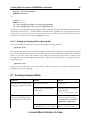
Table 1 Memory Requirements of VxWorks Components.........................................................18
Table 2 Typical RAD6000 Memory Map (4 MB Memory)........................................................26
Table 3 Supported TCW Sizes ....................................................................................................27
Table 4 Memory Configuration Variables..................................................................................28
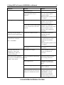
Table 5 Common Serial Communications Problems .................................................................33
Table 6 Segment Register Values for RSC Address Space ........................................................53
Table 7 Machine State Register...................................................................................................63
Table 8 Interrupt Offsets and Descriptions................................................................................64
Table 9 Private RAM Memory Map...............................................................................................74
1 About This Document
1
1 About This Document
This User’s Guide describes the system software available for Lockheed Martin’s radiation-hardened
RAD6000–based processor boards (collectively known as PSA–32), and the software development tools
available to write application–level software for those boards. The system software includes Wind River
Systems’ VxWorks operating system as well as one or more Board Support Packages (BSP), including start–
up code, device drivers, and other customizations, targeted for a particular board. The software
development system is the AdaMULTI toolset from Green Hills Software.
This document is not intended to replace existing manuals describing VxWorks, AdaMULTI, and the
POWER processor architecture. Rather, this document can be viewed as a bridge between these documents.
It will concentrate on the features of the RAD6000 processor and discuss how an application programmer
can take advantage of those features using the available system software and software development tools.
1.1 Who Should Use This Document
This document is intended for programmers who need to develop software for a RAD6000 processor. It is
assumed that the reader is familiar with the concepts behind developing real–time embedded software for
operating systems such as VxWorks. It is further assumed that the reader is familiar with using UNIX–like
operating systems, since the software development tools are hosted on this environment.
1.2 About The RAD6000
PSA–32 is the name given to Lockheed Martin’s line of 32–bit space processor subassemblies. These boards
are based on Lockheed Martin’s RAD6000 32–bit processor. The RAD6000 is a radiation hardened version
of IBM’s RISC Single–Chip (RSC) processor that was the precursor to the PowerPC line of processors.
Lockheed Martin provides several variations of the RAD6000 utilizing different busses and I/O devices to
meet the needs of a varied customer base.
1.3 VxWorks Version Differences
This manual was originally written in support of VxWorks version 5.1 and 5.2 and Green Hills tools version 1.8.7.
VxWorks version 5.3 (Tornado) and Green Hills version 1.8.8 have since been released. Some of the differences
between these versions are worth noting. For instance, SLIP has been replaced with raw serial as the communications
backend. In addition, the Tornado directory structure has changed. Where possible this manual has been updated to
reflect these version differences. However, should questions arise please refer to the appropriate documentation or
Lockheed Martin personnel to fully understand the differences.
1.4 How This Document Is Organized
This document is organized into the following sections:
Section 1. About This Document
Introductory information and overview.
Section 2. An Overview of the Software
Development Environment
Describes all of the pieces of software that comprise the
software development and run–time environments and
how they all fit together.
1 About This Document
2
Section 3. AdaMULTI on Your Host
Installing and using AdaMULTI.
Section 4. VxWorks on Your Host
Installing and using VxWorks.
Section 5. RAD6000 Board Support Packages
Installing and using a board support package (BSP).
Section 6. Pulling It All Together - How to
Build for Your Target
How to customize the system software and build it with
an application.
Section 7. Communicating over a Serial Port
Connecting and using the RAD6000’s serial port to load
and debug programs.
Section 8. Using SLIP to Connect a RAD6000 to Configuring and using SLIP to load and debug
programs.
a Network
Section 9.4. Error! Not a valid result for table.
Describes features specific to the RAD6000 processor,
such as interrupts, I/O, and the real–time clock; and
how to use them.
Section 11. Debugging with RISCWatch
Using RISCWatch to perform processor–level
debugging.
Appendices
Appendicies are added for board-specific I/O devices
(e.g., 1553, QHSS, Plasma)
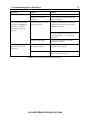
1.5 Conventions
This document uses the following conventions to differentiate certain elements:
TERM
EXAMPLE
Files, paths
“/usr/vw/config/rscvme/Makefile”
Books
PowerPC VxWorks Development Guide
Commands, function names
tar xv
Examples, display output
CONFIG_ALL = ../all/
Variables
Filename
Keyboard key
<RETURN>
1.6 Referenced Documents
The following documents will prove useful to programmers developing software for a RAD6000.
DOCUMENT
DOCUMENT DESCRIPTION
POWER Processor Architecture
Reference manual describing the processor architecture
of IBM’s POWER family, including the RAD6000.
Wind River Products Installation Guide (UNIX Installation instructions for VxWorks on UNIX
platforms.
Version)
VxWorks Release Notes
Version information on VxWorks.
VxWorks RAD6000 Release Notes
Version information on VxWorks for RAD6000 targets.
1 About This Document
3
DOCUMENT
DOCUMENT DESCRIPTION
VxWorks Programmer’s Guide
Overview and user’s guide for VxWorks.
VxWorks Reference Manual
Detailed reference manual of VxWorks system calls and
libraries.
Green Hills Installation Guide for UNIX
Installation instructions for Green Hills AdaMULTI
toolset.
MULTI Software Development Environment
User’s Guide
Overview and tutorial of Green Hills AdaMULTI toolset.
MULTI Ada Language User’s Guide and
Reference Manual
Reference manual for the Ada compiler available for
AdaMULTI.
MULTI C Language User’s Guide
Reference manual for the C compiler available for
AdaMULTI.
MULTI PowerPC VxWorks Development
Guide
Reference manual describing developing software for
VxWorks on the POWER architecture using Green Hills
AdaMULTI.
Morning Star PPP User Guide
User’s guide and reference manual for Progressive
System’s Morning Star PPP software.
RISCWatch User’s Manual
User’s guide and reference manual for IBM’s RISCWatch
tool.
2 An Overview of the Software Development Environment
4
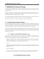
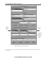
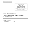
2 An Overview of the Software Development Environment
Development Workstation
Library
Manager
S/W Development Tools
C
Source
Ada
Source
Library
Compiler
Linker
VxWorks
O/S
Program
Object
ANSI C Compiler
Ada Compiler
Linker
Debugger
- Source
- Symbolic
Library Manager
RISCWatch
- Non Intrusive Debug
- Only for RS/6000 Microchannel
Debugger
Application
Programs
PSA-32 Software
UART Adapter
VxWorks
Basic Load Path
Loader
UART
RISCWatch
Software
RISCWatch
Adapter
PSA-32 Hardware
RAD6000
COP
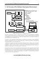
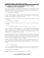
Figure 1 RAD6000 Software Development Environment
The PSA–32 single board computer is a RAD6000–based processor board. The RAD6000 is an IBM RISC
Single–Chip (RSC) manufactured to be radiation–hardened. To support embedded software development
for a RAD6000, the following products are commercially available: VxWorks by Wind River Systems, Inc.
and AdaMULTI by Green Hills Software, Inc.
VxWorks is a user-configurable real-time operating system that supports preemptive priority multitasking,
intertask communications, timers, and TCP/IP networking. VxWorks also includes a comprehensive
development platform for real–time applications.
AdaMULTI is an integrated development environment including an editor, compilers (Ada, C, Assembler,
and others are available), version control system, builder, and debugger. Please note that, despite the name,
AdaMULTI is not an Ada–only product. Developers may use the AdaMULTI product to develop C
language code that contains none of the Ada library code if desired.
These products combine to form an environment providing system services to application programs on the
RAD6000 target processor and a productive development interface on a host workstation running a UNIX–
like operating system. Several host systems are supported, including IBM RISC System/6000s running AIX
and Suns running Solaris. Consult with your Wind River, Green Hills, or Lockheed Martin representative
to inquire about currently supported hosts.
LOCKHEED M ARTIN FEDERAL SYSTEMS
3 AdaMULTI on Your Host
5
3 AdaMULTI on Your Host
AdaMULTI from Green Hills Software, Inc. provides a complete software development environment that
fully supports embedded real–time systems. It is available for a variety of host and target platforms and
includes an editor, compilers for a variety of languages, source level debugger, profiler, source code and
version controllers, and a multi–language program builder that are fully integrated in a window–based
system. Note that, despite the name, AdaMULTI may be used for developing either Ada or C language
applications.
The AdaMULTI product is shipped as a tape or CD containing the software and the following set of
manuals:
Installation Guide
MULTI Software Development Environment User’s Guide
Ada Language User’s Guide and Reference Manual
C Language User’s Guide
C++ Language User’s Guide
Embedded PowerPC Development Guide
If you are interested in getting an overview of the tools provided with AdaMULTI, the best place to start is
the MULTI Software Development Environment User’s Guide. However, as it is written as a tutorial to using the
toolset, it may be best to wait until the product has been installed before getting into it in too much detail.
The installation instructions are, obviously, in the Installation Guide. This manual contains installation
instructions for several different types of setups. The one you are interested in is “Installation for VxWorks
Products”. We’ll talk about this more in Section 3.1 Installing AdaMULTI.
The Embedded PowerPC Development Guide has a lot of good information for programmers developing
embedded software for VxWorks running on a PowerPC platform which applies to the RAD6000. The two
language guides provide information on Green Hills’ implementation of C and Ada.
The remainder of this section is an overview of the information found in these documents as they pertain to
developing software for VxWorks on a RAD6000. However, the intent is not to replace those documents
and, in the case of conflicts, the Green Hills’ documentation is probably correct.
3.1 Installing AdaMULTI
As mentioned above, the Installation Guide that ships with AdaMULTI contains a chapter called Installation
for VxWorks Products that provides very detailed instructions. This section tailors those instructions for
installation on both AIX and Solaris hosts. Other minor changes may be necessary for other hosts and/or
for your environment. Of course, Green Hills may change the installation method for future releases. We
recommend that you compare the information in this section with the information provided with
AdaMULTI to determine what needs to be done to install the product in your environment.
Note that if you are going to be using the floating license manager, make sure to perform these instructions
while logged on to the host which is to run the license manager daemon. Also, the user performing the
installation must have write access to the directory under which the program is to be installed. However, it
LOCKHEED M ARTIN FEDERAL SYSTEMS
3 AdaMULTI on Your Host
6
is best if the software is not installed by the root user, since this may require significant changes to the file
permissions after the installation has completed in order for other users to access the software.
1.
The first step is to create a directory for the AdaMULTI product which is accessible by everyone on the
development team. The AdaMULTI documentation suggests creating that directory under the “/usr”
directory. Here at Lockheed Martin Manassas, we use a directory named “/proj”. If you are unsure
where to create the AdaMULTI directory, discuss it with your system administrator. We definitely
recommend that the software not be installed in a subdirectory of a user’s home directory.
Once you’ve decided where to install the software, you need to decide on the name for the directory. We
recommend “green” as that is what the AdaMULTI documentation uses. This is done with the
following commands:
cd /usr
mkdir green
cd green
2.
Once a shared AdaMULTI directory has been created, the product tape or CD can be installed into it.
This is done using the tar command. Usually the tape drive attached to your workstation has been
designated the default device for tar. If this is the case, you need only enter the following, after inserting
the AdaMULTI product tape into the tape drive:
tar xv
If, however, the tape drive you wish to use is not the default device, you will need to enter the device
name as part of the tar command. For example, if the tape drive you wish to use is installed as
“/dev/rmt1”, use this command instead:
tar xvf /dev/rmt1
If you are unsure which of the above to use, try the first one first. If this doesn’t work and you don’t
know the device name for your tape drive, contact your local system administrator for assistance.
3. After loading the contents of the tape, you will need to run the AdaMULTI install script. Please read the
installation instructions in the AdaMULTI documentation closely at this point, as there are a number of
possible scenarios for exactly how to continue. For example, you may have to run the update program
before running the install script. If so, you will have to contact Green Hills at the phone number or
address listed in the Installation Guide and provide them with some information about your system in
order to get a software key needed to use AdaMULTI on your system. If you are unsure how to continue
at this point, please contact Green Hills for more information.
For the purposes of this document, we’ll describe how to continue once you reach the point of running
the install script. If you have problems performing this step, contact Green Hills as mentioned before.
To run the install script, merely enter:
install.sh
The install script will ask you for the name of the directory in which the product is to be installed:
Enter an absolute pathname for the current directory or press return to use
/usr/green:
LOCKHEED M ARTIN FEDERAL SYSTEMS
3 AdaMULTI on Your Host
7
Assuming the default (”/usr/green”) is correct, you should merely press <RETURN>. However, if you
chose to install the software in another directory, enter that directory name and press <RETURN>.
You will next be shown a list of product executables that have been placed in the installation directory.
After this you will be asked whether you wish the executables to be copied to “/usr/bin”:
Press <return> to copy files to /usr/bin, or ’n’ to skip:
Copying the files to “/usr/bin” has the advantage that user’s will be able to access them without
having to change their PATH. However, it has the disadvantage of polluting the directory, which
makes it more difficult to uninstall the product if this becomes necessary. At Lockheed Martin, we
recommend entering ’n’ at this prompt so that the files are not copied.
The installation of AdaMULTI is now complete. If you have trouble, please call Green Hills.
3.2 AdaMULTI and Your Environment
You now need to make the AdaMULTI tools available by setting some environment variables. For
simplicities sake, these can be placed in a shell script to which all of the software developers have access,
and that shell script can be called from each user’s “.profile”, “.kshrc”, or “.cshrc” file.
If you are using the Korn Shell (ksh), use the following commands:
export ADABASE=/usr/green/vxrsc
export PATH=$PATH:/usr/green:/usr/green/adabin
If you are using the C Shell (csh), use the following commands:
setenv ADABASE /usr/green/vxrsc
setenv PATH ${PATH}:/usr/green:/usr/green/adabin
Note that if these commands are entered directly at the shell, instead of being run from the “.cshrc” file, you
may also need to use the following command:
rehash
If you are using a shell other than ksh or csh, refer to the documentation for your shell to determine the
proper syntax for setting these environment variables.
The above examples assume that AdaMULTI was installed in the “/usr/green” directory, as in the
examples in Section 3.1. If a different directory was used, use the correct name.
3.3 Using AdaMULTI
The AdaMULTI toolset may be used either from the Builder, which provides a GUI, or from the UNIX
command line. If you have never used MULTI before, we highly recommend you try the tutorial contained
in the MULTI Software Development Environment User’s Guide.
LOCKHEED M ARTIN FEDERAL SYSTEMS
3 AdaMULTI on Your Host
8
3.3.1 Compiling C Programs
The C compiler can be invoked from the command line with the following command:
ccppc -cpu=rsc -nosda -nostdinc -ansi filename
(GHS version 1.8.7)
ccvxppc -cpu=rsc -nosda -nostdinc -ansi filename (GHS version 1.8.8)
In addition, programs that need to use floating point zero-divide checking should add the following flag:
-check=zerodivide
Refer to the Green Hills documentation for a complete description of the available flags.
3.3.2 Compiling and Linking Ada Programs with GHS Version 1.8.7
Before compiling your first Ada program for a given project, you must create an Ada library for that project.
This is done with the following command, which will create the Ada library in the current directory:
newlib
After the Ada library has been created, you can compile an Ada file using the following command:
ada filename
The compiler will place the compiled code in the Ada library. When you are ready to build an executable
program using an Ada main procedure, you can use the following command:
bamp proc
where proc is the name of the Ada main procedure. Refer to the Green Hills documentation for more
information on all of these commands.
3.3.3 Compiling and Linking Ada Programs with GHS Version 1.8.8
The VxWorks cross compiler for GHS version 1.8.8 and Ada95 is acvxppc, the newlib command is not needed for
version 1.8.8.
acvxppc –cpu=rsc filename
The Ada linker is called alxvxppc.
alxvppc proc
where proc is the name of the Ada main procedure. Refer to the Green Hills documentation for more
information on all of these commands.
3.3.4 Assembling RAD6000 Assembly Programs
Assembler modules are pre-processed and then compiled using the following commands:
LOCKHEED M ARTIN FEDERAL SYSTEMS
3 AdaMULTI on Your Host
9
3.3.4.1 GHS Version 1.8.7
cpp filename > tmp.s
ccppc –o filename.o tmp.s
3.3.4.2 GHS Version 1.8.8
cppppc filename > tmp.s for (GHS version 1.8.8)
ccvxppc –o filename.o tmp.s
Refer to the Green Hills documentation for more information on the options available for these commands.
LOCKHEED M ARTIN FEDERAL SYSTEMS
4 VxWorks on Your Host
10
4 VxWorks on Your Host
VxWorks is a popular, mature real–time operating system available from Wind River Systems, Inc. It is
available for a variety of target platforms, including the RAD6000. Although the VxWorks product comes
with a few tools to help programmers build their target application, it is, strictly speaking, not a tool itself
but an operating system.
The VxWorks product comes with one or two tapes or CD containing the software and the following set of
manuals:
Wind River Products Installation Guide
VxWorks Programmer’s Guide
VxWorks Reference Manual
VxWorks Release Notes
Tornado User’s Guide*
Tornado API Guide*
Tornado Release Notes*
* - forVxWorks version 5.3 or later
You may also receive manuals relating to the GNU toolkit. Lockheed Martin does not support GNU for the
RAD6000, so these manuals are not necessary.
If the software is delivered on only one tape, it should contain just the operating system and host tools. If
two tapes are delivered, one should contain the operating system and host tools, and the other should
contain the BSP for the VME–based RAD6000. Note that other BSPs, such as the ASCM Module Bus, are
available from Lockheed Martin and not from Wind River Systems. If you are using one of these BSPs, you
do not need to install the VME–based BSP. See Section 5 RAD6000 Board Support Packages for information on
installing Lockheed Martin–provided Board Support Packages.
The VxWorks Programmer’s Guide is an excellent document for getting started. It contains an overview of the
VxWorks product and a very detailed chapter on installation. It is highly recommended that you read that
now, especially if you are unfamiliar with VxWorks and/or real–time operating systems in general.
The VxWorks Reference Manual contains descriptions of all of the VxWorks libraries and system calls. It is
invaluable during application program development, but not of interest now.
The Tornado User’s Guide is the central documentation for the Tornado development environment. It
includes a global overview of Tornado, instructions on how to configure your environment and set up
communications with a target system, a chapter on each of the interactive Tornado tools and appendices on
the use of Tcl, the Tool Command Language and Tornado directories and files.
The Tornado API Guide is a detailed reference fro developers who wish to extend the Tornado development
environment. It discusses the Tornado architecture from the perspective of software APIs and protocols, and
describes how to extend and modify the Tornado tools and how to integrate them with your own software.
Much of the remaining information in this section has been culled from the Wind River Products Installation
Guide and the VxWorks Programmer’s Guide, but the intent is not to replace that document. Rather, this
section concentrates on those sections that are most applicable to using VxWorks for the RAD6000.
LOCKHEED M ARTIN FEDERAL SYSTEMS
4 VxWorks on Your Host
11
However, the documentation that ships with VxWorks should be considered the most up–to–date and, in
the case of conflicts, is probably correct.
4.1 Installing VxWorks1
This section provides an overview of the installation process tailored for the version of VxWorks targeted for
the RAD6000 and hosted on either an IBM RISC System/6000 AIX or Sun Solaris workstation. The
instructions may be slightly different for other hosts, and, of course, Wind River Systems may change the
method used to install VxWorks in future releases. We recommend that you compare the information in this
section with the information provided with VxWorks to determine what needs to be done to install
VxWorks in your environment.
1.
The first step is to create a directory for the VxWorks product that is accessible by everyone on the
development team. Here at Lockheed Martin Manassas we have a high–level directory named “/proj”
that is accessible from all workstations on our internal network. If you have a similar setup that would
be an ideal place to create the VxWorks directory. If not, you should talk to your system administrator
about where the software should be installed. We definitely recommend that the software not be
installed in a subdirectory of a user’s home directory.
Once you’ve decided where to install the software, you need to decide on the name for the directory.
The VxWorks Programmer’s Guide recommends using the name “vw”. Here at Lockheed Martin, we
use the name “vxworks”. It doesn’t matter much, so long as the name is unique. In this section, we will
use the VxWorks naming convention to keep things simple.
Now that you’ve decided where to install the software and what to call the directory, you can actually
create it. This is done with the following commands:
cd /usr
mkdir vw
cd vw
2.
Once a shared VxWorks directory has been created, the product tape can be installed into it. This is
done using the tar command. Usually the tape drive attached to your workstation has been
designated the default device for tar. If this is the case, you need only enter the following, after inserting
the VxWorks product tape (not the tape containing the Board Support Package) into the tape drive:
tar xv
If, however, the tape drive you wish to use is not the default device, you will need to enter the device
name as part of the tar command. For example, if the tape drive you wish to use is installed as
“/dev/rmt1”, use this command instead:
tar xvf /dev/rmt1
If you are unsure which of the above to use, try the first one first. If this doesn’t work and you don’t
know the device name for your tape drive, contact your local system administrator for assistance.
1
This is a tailored installation process for VxWorks versions 5.2 and earlier. If you are installing version 5.3 and later,
please refer to the Wind River Products Installation Guide for Tornado.
LOCKHEED M ARTIN FEDERAL SYSTEMS
4 VxWorks on Your Host
3.
12
If there is a separate tape for the RAD6000 Board Support Package, it should be installed after the
VxWorks product tape. Insert the BSP tape into the tape drive now (while still in the “/usr/vw”
directory) and enter the following command:
bin/host/installOption
where host is rs6000 if you are installing on an IBM RISC/System 6000 workstation, or solaris if
you are installing on a Sun Solaris workstation.
Note that if the tape drive is not the default drive you must tell the program which device to use. For
example, if the tape drive is “/dev/rmt1”, use this command instead:
bin/host/installOption -f /dev/rmt1
4.
The final step of the installation process is to create a symbolic link to allow the Green Hills compilers
access to the VxWorks header files. This is done with the following commands:
cd /usr/green/vxworks
ln -s /usr/vw/h usrinc
Obviously if the directory names you used when installing the products differ from the above, you must
use the correct names.
That’s all there is to the installation of VxWorks and the RAD6000 Board Support Package.
4.2 VxWorks Directory Structure
After installing VxWorks on your host, you will have available the libraries and header files documented in
the VxWorks Reference Manual, as well as some tools used to build VxWorks and your application programs.
The directory structure is as follows:
./bin
Contains one or more subdirectories, each of which contains the executable
VxWorks software development tools for a particular host. For example, if you
have VxWorks hosted on an IBM RISC System/6000, there should be a directory
named “./bin/rs6000”.
./config/all
Contains target–independent system configuration modules for VxWorks.
./config/rscvme
Contains VxWorks system configuration modules used solely for the VME–
based RAD6000.
./h
Contains the VxWorks header files.
./lib
Contains the VxWorks machine–independent object libraries.
./man
Contains VxWorks documentation in UNIX man page format.
./src
Contains VxWorks source files. Any source files that are expected to be modified
by the application software developer, such as configuration files and device
drivers are always shipped. Other source files will be here only if a source
license was purchased from Wind River Systems, Inc.
For more information on these directories and their contents, refer to the VxWorks Programmer’s Guide.
LOCKHEED M ARTIN FEDERAL SYSTEMS
4 VxWorks on Your Host
13
4.3 VxWorks and Your Environment
You will need to set up several environment variables in order to build VxWorks images and develop
application software for VxWorks. For simplicities sake, these can be placed in a shell script to which all of
the software developers have access, and that shell script can be called from each user’s “. profile”,
“.kshrc”, or “.cshrc” file.
If you are using the Korn Shell (ksh), use the following commands for VxWorks versions 5.2 and earlier:
export
export
export
export
export
export
VX_VW_BASE=VxWorks-base-directory
VX_HSP_BASE=$VX_VW_BASE
VX_BSP_BASE=$VX_VW_BASE
VX_HOST_TYPE=host
PATH=$PATH:$VX_VW_BASE/bin/$VX_HOST_TYPE
MANPATH=$MANPATH:$VX_VW_BASE/man
In the above example, VxWorks-base-directory should be the name of the directory created to hold
VxWorks during the installation process, e.g. “/usr/vw”. host should be the name used to identify your
host workstation: rs6000 if your software is hosted on an IBM RISC/System 6000 AIX workstation, or
solaris if your software is hosted on a Sun Solaris workstation. If you are unsure of what host should
be, refer to the VxWorks Programmer’s Guide that lists all the valid values.
If you are using the Korn Shell (ksh), use the following commands for VxWorks versions 5.3 and later:
export WIND_BASE=installation directory for Tornado (e.g. “/usr/torn”)
export WIND_HOST_TYPE=name of host type (e.g. “sun4-solaris2”)
export WIND_REGISTRY=name of host where regsitry is running
export PATH=$PATH:$WIND_BASE/host/$WIND_HOST_TYPE/bin
export LM_LICENSE_FILE= path to license-key repository file (e.g.
“/usr/torn/.wind/license)
export MANPATH=$MANPATH:$WIND_BASE/host/man:$WIND_BASE/target/man
If you are using the C Shell (csh), use the following commands for VxWorks versions 5.2 and earlier:
setenv
setenv
setenv
setenv
setenv
setenv
VX_VW_BASE VxWorks-base-directory
VX_HSP_BASE ${VX_VW_BASE}
VX_BSP_BASE ${VX_VW_BASE}
VX_HOST_TYPE host
PATH ${PATH}:${VX_VW_BASE}/bin/${VX_HOST_TYPE}
MANPATH ${MANPATH}:${VX_VW_BASE}/man
If you are using the Korn Shell (ksh), use the following commands for VxWorks versions 5.3 and later:
setenv WIND_BASE installation directory for Tornado (e.g. “/usr/torn”)
setenv WIND_HOST_TYPE name of host type (e.g. “sun4-solaris2”)
setenv WIND_REGISTRY name of host where registry is running
setenv PATH $PATH:$WIND_BASE/host/$WIND_HOST_TYPE/bin
setenv LM_LICENSE_FILE path to license-key repository file (e.g.
“/usr/torn/.wind/license)
setenv MANPATH $MANPATH:$WIND_BASE/host/man:$WIND_BASE/target/man
LOCKHEED M ARTIN FEDERAL SYSTEMS
4 VxWorks on Your Host
14
Note that if these commands are entered directly at the shell, instead of being run from the .cshrc file, you
may also need to use the following command:
rehash
If you are using a shell other than ksh or csh, refer to the documentation for your shell to determine the
proper syntax for setting these environment variables.
After finishing the installation process and setting up the environment variables, you are now ready to
begin developing software for use with VxWorks.
4.4 Setting up the Tornado Registry
Before anyone at your site can use Tornado, someone must set up the Tornado Registry, a daemon that keeps track
of all available targets by name. Only one registry is required on your network, and it can run on any networked host.
The registry daemon must always run; otherwise Tornado tools cannot locate targets. Thus, it is best to add
commands to start up the daemon in a system start-up file.
To start the daemon from a command line, execute wtxregd in the background. For example, on a Sun host running
Solaris OS:
% /usr/torn/host/sun4-solaris2/bin/wtxregd –V > /tmp/wtxregd.log &
The Tornado tools locate the registry daemon through the environment variable WIND_REGISTRY. If this variable
is not set at all, the tools will look for the registry daemon on the local host.
LOCKHEED M ARTIN FEDERAL SYSTEMS
5 RAD6000 Board Support Packages
15
5 RAD6000 Board Support Packages
A Board Support Package (BSP) contains system configuration modules and services that tailor VxWorks
for a particular board. It includes start–up routines, interrupt handlers, device drivers, and other machine–
dependent modules.
Wind River Systems, Inc. provides the BSP for Lockheed Martin’s RSCVME board with VxWorks. The
RSCVME is a RAD6000 with a VMEbus interface. BSPs for other variations of the RAD6000 family, such as
the ASCM Module Bus, are available from Lockheed Martin.
If you are using a RSCVME, your BSP should already have been installed when you installed VxWorks and
you can ignore this section. See Section 4 VxWorks on Your Host for more information.
This section will discuss how to install and set up BSPs received from Lockheed Martin.
5.1 Installing a Board Support Package
Lockheed Martin always ships formal deliveries of a Board Support Package on magnetic media. However,
under some circumstances an informal delivery of a BSP may be made if acceptable to both Lockheed Martin
and the receiving customer. Informal deliveries may be made via electronic mail or file transfer protocol (ftp)
if the receiving customer has access to the Internet and is willing to accept delivery in this fashion.
You will need to perform these steps on a machine that has access to the directory in which you installed
VxWorks. The installation script used to install the BSP will use the environment variables defined during
the installation of VxWorks to determine where to install the software. So you must have these variables
defined before proceeding.
5.1.1 Preparing to Install a BSP from Diskette or Tape
The first step is to load the installation script on your machine. The installation script, along with a file
containing the BSP, is delivered in tar format. They should be placed in either a user directory or a temp
directory. They should not be placed in the VxWorks installation directory.
1.
Change to the directory where you want to place the installation script and then load the tape or
diskette in the appropriate drive. After this has been done, you can use the following command to
unload the tape (assuming the device being used is the default device):
tar xv
If the device being used is not the default device, you will need to enter the device name as part of the tar
command. For example, if the tape drive you wish to use is installed as “/dev/rmt1”, use this
command instead:
tar xvf /dev/rmt1
If you are unsure which of the above to use, try the first one first. If this doesn’t work and you don’t
know the device name for your tape drive, contact your local system administrator for assistance.
LOCKHEED M ARTIN FEDERAL SYSTEMS
5 RAD6000 Board Support Packages
16
Now skip to Section Error! Reference source not found. Error! Reference source not found., to finish the
installation.
5.1.2 Preparing to Install a BSP from an Internet Delivery
Internet deliveries are made via e–mail or anonymous ftp from an Internet–connected Lockheed Martin site.
An e–mail delivery will arrive in the form of a uuencoded, compressed, tar file. An ftp delivery will arrive in
the form of a compressed tar file. The file name and IP address of the ftp site will be provided by your
Lockheed Martin representative when a delivery is available.
Once you have received the file, the first step in the installation process is to load the installation script on
your machine. Place the delivered file in either a user directory or a temp directory. It should not be placed
in the VxWorks installation directory.
1.
If you received the BSP by anonymous ftp, skip this step. It applies only to e–mail deliveries.
Name the received file “bsp.uue” and then use the following command to decode it:
uudecode bsp.uue
This will create a file called “bsp.i.date.tar.Z”, where date is the date the BSP was built.
2.
From the directory containing the file “bsp.i.date.tar.Z”, enter the following:
uncompress bsp.i.date.tar.Z
This will create a file called “bsp.i.date.tar”.
3.
Now use the following commands to install the BSP to a shared directory:
tar –xvf bsp.i.date.tar
Your BSP is now installed under the “config/xxxxxx” directory of your VxWorks installation directory,
where ‘xxxxxx’ is your project name. If you have problems, please contact your Lockheed Martin
representative.
LOCKHEED M ARTIN FEDERAL SYSTEMS
6 Pulling It All Together - How to Build for Your Target
17
6 Pulling It All Together - How to Build for Your Target
The VxWorks operating system allows application programs to be either linked with VxWorks or linked as
separate load modules. By taking advantage of VxWorks capabilities such as networking and the
interactive shell, separately linked application programs can be loaded dynamically on a target board by
VxWorks. Since this feature is invaluable during development and debug, we recommend that during these
stages application programs should not be linked with VxWorks. Eventually, however, you will probably
want to link them together to create a stand–alone, bootable application.
The VxWorks Programmer’s Guide contains a chapter called “Configuration” which discusses building
VxWorks both separate from, and linked with, an application program. This section will look at some of the
issues raised in that chapter as they relate to building for a RAD6000 board.
6.1 Creating a Build Directory
The first thing you should consider doing is creating a build directory that is separate from the VxWorks
installation directory. This is especially useful if multiple projects will be sharing one VxWorks installation
or if a single project wants to test various VxWorks configurations. Another reason to create a build
directory is to keep the original VxWorks installation intact in case problems due to configuration changes
develop.
If you decide to create a build directory, you will need to decide where to place it. If the build directory will
be used by several developers, it should be placed in a common location where all can access it. If it will
only be used by one developer, that user’s home directory is good. Keep in mind that you want it in a place
where everyone who needs it has access to it, but that you don’t want a situation where a developer
inadvertently causes problems for others due to configuration changes.
Once you have decided where to place it, change to that directory and copy everything under
$WIND($VX_VW)_BASE/target/config. A simple way to do this is:
cp -r $WIND($VX_VW)_BASE/config .
Now change to the BSP directory under the “config” directory (probably “rscvme” or “psa32”) and use your
favorite editor to edit the file “Makefile(.RSCgreen)”. Change the line that sets the CONFIG_ALL variable to
the following:
CONFIG_ALL = ../all/
Once that has been done, you need to verify that the file “Makefile” has the correct definitions for the target
CPU and the development toolset. Edit the file using your favorite editor and ensure the following variables
exist and are set to the proper values:
CPU = RSC
TOOL = green
LOCKHEED M ARTIN FEDERAL SYSTEMS
6 Pulling It All Together - How to Build for Your Target
18
6.2 Including Only the Capabilities You Need
You should consult the VxWorks Programmer’s Guide for a discussion of VxWorks components and their
uses. This section will highlight some common configurations already tried on the RAD6000.
One of the first big decisions you need to make is whether to include networking and/or the interactive
shell. The networking component, in conjunction with SLIP (Serial Line/Interface Protocol) or an Ethernet
driver, allows the target RAD6000 to be connected to a local area network (LAN). This permits the target
board to be used remotely and also allows applications to be downloaded dynamically. If networking is not
included, application programs must be linked with VxWorks before downloading.
The interactive shell provides a command line for interacting with VxWorks. This also aids in dynamically
downloading programs and fixes, and provides many interactive debugging features.
Other components you should consider using during program development include symbolic debug
information and the remote debugger, both of which are necessary to take advantage of AdaMULTI’s source
level remote debugger.
Lockheed Martin highly recommends using both networking and the interactive shell during program
development, assuming your RAD6000 has enough memory to include these components. VxWorks image
sizes built to date have varied from an 800 KB image which included a SLIP network connection, interactive
shell, remote debugger, symbolic debug information, Ada Runtime Environment, and the VxWorks kernel;
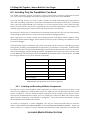
to a 250 KB image which included only the Ada Runtime Environment and the VxWorks kernel. See Table
1 for the approximate sizes of various VxWorks components.
Component
Approximate Size (KB)
VxWorks Kernel
100
Ada Runtime Environment
150
SLIP
135
Interactive Shell
145
Symbolic Debug Information
50
Remote Debugger
200
Table 1 Memory Requirements of VxWorks Components
6.2.1 Including and Excluding VxWorks Components
Now that you’ve given some thought to which components you want to use, and which you don’t, we will
look at how to configure your VxWorks build. In the “all” subdirectory of your build directory, there is a file
named “configAll.h”. This file determines which components will be included when VxWorks is built.
Note that the Ada Runtime Environment, since it is actually part of the Green Hills Ada Compiler rather
than a VxWorks component, is not handled in “configAll.h”. See Section 6.2.2 for information on linking
the Ada Runtime Environment with VxWorks.
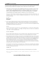
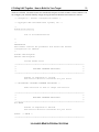
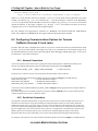
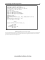
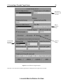
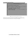
An outline of “configAll.h” is shown in Figure 2. The only two sections that matter here are under the
banners “INCLUDED SOFTWARE FACILITIES” and “EXCLUDED SOFTWARE FACILITIES”. Under each
of these sections is a collection of macro definitions that determine which components are included and
LOCKHEED M ARTIN FEDERAL SYSTEMS
6 Pulling It All Together - How to Build for Your Target
19
which are excluded. The macro names are somewhat descriptive and each contains a short comment. You
can configure your VxWorks build by simply moving the macro definitions between the two sections.
/* configAll.h - default configuration header */
/* Copyright 1984-1993 Wind River Systems, Inc. */
/*
modification history
-------------------List of File Modifications
*/
/*
DESCRIPTION
This header contains the parameters that define the default
configuration for VxWorks.
*/
#ifndef INCconfigAllh
#define INCconfigAllh
Include Header Files
/**********************************************************************/
/*
*/
/*
INCLUDED SOFTWARE FACILITIES
*/
/*
*/
/**********************************************************************/
Defines of Components to Include
This section should be customized for your build.
/* CPU-SPECIFIC INCLUDED SOFTWARE FACILITIES */
There should be no need to change this section.
/**********************************************************************/
/*
*/
/*
EXCLUDED SOFTWARE FACILITIES
*/
/*
*/
/**********************************************************************/
#if FALSE
Defines of Components to Exclude
This section should be customized for your build.
#endif
/* FALSE */
/**********************************************************************/
LOCKHEED M ARTIN FEDERAL SYSTEMS
6 Pulling It All Together - How to Build for Your Target
20
/*
*/
/*
KERNEL SOFTWARE CONFIGURATION
*/
/*
*/
/**********************************************************************/
Nothing below this point should be configured.
#endif
/* INCconfigAllh */
Figure 2 Outline of file “configAll.h”
6.2.2 The Ada Runtime Environment
Ada programs require the use of an Ada Runtime Environment. AdaMULTI allows software developers to
choose one of two methods for providing the services of the Ada Runtime Environment to their application
programs. The first method is to link those services that are used by a given Ada program directly with that
program. The second method is to link the Ada Runtime Environment with the VxWorks operating system
so that each Ada program need not contain its own copy of these services.
There is a tradeoff in deciding which of these methods is best for you. Linking the services with your
application programs saves memory space if your system comprises only one or a few Ada programs each
using only a few of the Ada Runtime Environment services. However, if there are many Ada programs or
just a few Ada programs each requiring many runtime services, linking the Ada Runtime Environment with
VxWorks will reduce memory requirements. You will need to decide for yourself which is the best option
and then perform the instructions in one of the next two sections.
6.2.2.1 Linking the Ada Runtime Environment with VxWorks
To build the Ada Runtime Environment into VxWorks, you need to add the Green Hills Ada libraries to the
list of object files to be linked with VxWorks. To do this, use your favorite editor to edit the file
“Makefile.RSCgreen” in your build directory. Find the lines that set the LIBS variable and add the following
five lines:
$(ADABASE)/adalib/libs.o
$(ADABASE)/adalib/lowrt_wr.a
$(ADABASE)/adalib/lowtask_wr.a
$(ADABASE)/adalib/predef_wr.a
$(ADABASE)/adalib/util_wr.a
\
\
\
\
Make sure that all lines except for the last one end with a line continuation character (”\”). Once you have
done this, save the file and exit the editor.
Now go to the Ada library under the ADABASE directory and copy the following files:
cd
cp
cp
cp
cp
$ADABASE/adalib
lowrt_blank.a lowrt.a
lowtask_blank.a lowtask.a
predef_blank.a predef.a
util_blank.a util.a
LOCKHEED M ARTIN FEDERAL SYSTEMS
6 Pulling It All Together - How to Build for Your Target
21
Finally, edit the file named “ada” using your favorite editor. Search the file for two lines that look
something like this:
#.o.:$wrld $ldflags -sde -o $final.o -r $(lib)btmain.o $objects
$linkobjects $tasklib $adaar $endargs
.o.:$wrld $ldflags -sde -o $final.o -r -e tmain $(lib)btmain.o
$(lib)amain.o $(lib)bamain.o $objects $linkobjects
If there is a comment character (”#”) in front of the first line and not in front of the second line (as shown
above), you don’t need to modify the file. If not, comment out the first of the two lines and make sure the
other is not commented out.
Once all of this is done, you can rebuild VxWorks and it will contain the Ada Runtime Environment.
6.2.2.2 Linking the Ada Runtime Environment with Your Application Programs
To build the required services of the Ada Runtime Environment into each Ada application program, you
need to edit the file “Makefile.RSCgreen” in your build directory using your favorite editor. Find the lines
that set the LIBS variable and remove the following five lines, if they exist:
$(ADABASE)/adalib/libs.o
$(ADABASE)/adalib/lowrt_wr.a
$(ADABASE)/adalib/lowtask_wr.a
$(ADABASE)/adalib/predef_wr.a
$(ADABASE)/adalib/util_wr.a
\
\
\
\
Those lines can be physically deleted, or just commented out by placing a “#” at the beginning of each line.
Make sure, however, that the last non–comment line of the statement does not end with a line continuation
character (”\”).
Now go to the Ada library under the ADABASE directory and copy the following files:
cd
cp
cp
cp
cp
$ADABASE/adalib
lowrt_wr.a lowrt.a
lowtask_wr.a lowtask.a
predef_wr.a predef.a
util_wr.a util.a
Finally, edit the file named “ada” using your favorite editor. Search the file for two lines that look
something like this:
.o.:$wrld $ldflags -sde -o $final.o -r $(lib)btmain.o $objects $linkobjects
$tasklib $adaar $endargs
#.o.:$wrld $ldflags -sde -o $final.o -r -e tmain $(lib)btmain.o
$(lib)amain.o $(lib)bamain.o $objects $linkobjects
If there is a comment character (”#”) in front of the second line and not in front of the first line (as shown
above), you don’t need to modify the file. If not, comment out the latter of the two lines and make sure the
other is not commented out.
LOCKHEED M ARTIN FEDERAL SYSTEMS
6 Pulling It All Together - How to Build for Your Target
22
Once all of this is done, you can rebuild VxWorks so that it does not contain the Ada Runtime Environment.
After this, whenever you build your application programs, they will include those runtime services that
they need.
6.3 Linking Your Application Program with VxWorks
If you are building VxWorks without the networking facilities, you will need to link your application
program with VxWorks — otherwise you will have no way of loading the program onto the target board
once VxWorks is loaded. Also, eventually you will probably want to link your application with VxWorks
whether or not you plan on using the networking facilities in your operational system.
Two steps are required to do this. First, you need to edit the file “Makefile.RSCgreen” in the BSP
subdirectory of your build directory to add the names of the object file(s) that comprise your program.
Second, you need to create a dummy reference to the first function of your program to gain control. This is
necessary because the linker will remove object files that contain only unreferenced symbols.
As an example, let’s assume you have a C language function named “user_proc” contained in a source file
named “user.c” that you want to link with the VxWorks image. Compiling this source file will create an
object file named “user.o” which needs to be added to the makefile, ”Makefile.RSCgreen”, in your build
directory. To do this, use your favorite editor to edit that file and set the MACH_LIBS variable as follows:
MACH_LIBS = user.o
Next edit the file “userLink.c” and add the following lines:
/* User functions */
void User_Fns (void) {
user_proc();
}
This last reference creates the dummy reference to your function, as mentioned above. Although the
function, “User_Fns”, is never called by another function, because it is in an object file that will be linked
when VxWorks is built, it fools the linker into thinking that your function, “user_proc”, is being called.
Therefore the linker will include your object file as desired.
As another example, let’s add an Ada language procedure named “ada_main” contained in a source file
named “user.ada” to the VxWorks image. Again, use your favorite editor to edit “Makefile.RSCgreen” and
set the MACH_LIBS variable as follows:
MACH_LIBS = user.o
Then edit the file “userLink.c” and add the following lines:
/* User functions */
void User_Fns (void) {
ada_main();
}
Once your program is linked with VxWorks, they can be invoked from the shell command line. For more
information, see the VxWorks Programmer’s Guide.
LOCKHEED M ARTIN FEDERAL SYSTEMS
6 Pulling It All Together - How to Build for Your Target
23
6.4 Configuring Communications Options for Pre-Tornado
(VxWorks Version 5.2 and Earlier)
Now, let’s discuss the options for communicating with your target board. Lockheed Martin provides some
preset VxWorks configurations: one for an interactive shell via the UART, one for SLIP connection via the
UART, and one for TCP/IP over an ethernet device. To use the shell, go to the “all” directory under your
build directory and copy “configAll.shell” to “configAll.h”:
cp configAll.shell configAll.h
You must then rebuild VxWorks. The shell will become active when VxWorks is started on the target
computer. The local debugger and symbol information will still be available. When building without
network capability you must link user programs with VxWorks.
To use a SLIP connection requires more setup than the shell. First get the proper “configAll.h” by copying
“configAll.slip”:
cp configAll.slip configAll.h
Next, edit the file “config.h” to inform VxWorks of the IP address and name of the target computer and the
host computer.
#define DEFAULT_BOOT_LINE \
”sl(0,0)HOST:SYMBOLFILE h=HOSTADDR e=TARGETADDR u=USER tn=TARGET”
Where HOST is the IP name of the host computer, SYMBOLFILE is the name of the symbol file to use when
loading via network (e.g., “/u/USER/vxWorks.sym” — but this parameter is unused on the RAD6000),
HOSTADDR is the dotted decimal IP address of the host computer (e.g., 90.0.0.1), TARGETADDR is the dotted
decimal IP address of the target computer (e.g., 90.0.0.2), USER is a username accessible on the host
computer, and TARGET is the IP name of the target computer.
The DEFAULT_BOOT_LINE must match the configuration found on the host machine. In particular, the
host and target computers must agree on the IP names and addresses. The host may have a different IP
address for the SLIP connection than it does for its normal network connection (maybe Ethernet), but
whatever name and address it believes itself to be on the SLIP port, the target must be informed. See Section
8 for more information on configuring SLIP on the host workstation.
In addition to setting the communications configuration in DEFAULT_BOOT_LINE, you will probably also
want to configure VxWorks to initialize the network connection during startup. To do this, edit the file
“usrConfig.c” and define the variable INCLUDE_NET_INIT immediately prior to the line testing for its
existence:
#define INCLUDE_NET_INIT
#ifdef INCLUDE_NET_INIT
Those who have a VME–based RAD6000 target computer have an additional option, VME–based Ethernet.
The setup for the Ethernet is very similar to the SLIP setup. For this option, use the “configAll.enp” file:
cp configAll.enp configAll.h
In addition, the DEFAULT_BOOT_LINE must be set for Ethernet in the file “config.h”:
LOCKHEED M ARTIN FEDERAL SYSTEMS
6 Pulling It All Together - How to Build for Your Target
24
#define DEFAULT_BOOT_LINE \
”enp(0,0)HOST:SYMBOLFILE h=HOSTADDR e=TARGETADDR u=USER tn=TARGET”
Where HOST is the IP name of the host computer, SYMBOLFILE is the name of the symbol file to use when
loading via network (e.g., “/u/USER/vxWorks.sym” — but this parameter is unused on the RAD6000),
HOSTADDR is the dotted decimal IP address of the host computer (e.g., 90.0.0.1), TARGETADDR is the dotted
decimal IP address of the target computer (e.g., 90.0.0.2), USER is a username accessible on the host
computer, and TARGET is the IP name of the target computer.
The only ethernet card supported by VxWorks on a RAD6000 is the Rockwell ENP–10L VME Ethernet
board. Non–VME–based RAD6000s do not support ethernet.mjf update this for RAMix
6.5 Configuring Communications Options for Tornado
(VxWorks Versions 5.3 and Later)
Tornado offers the same communication options as previous versions but with some enhancements. With
Tornado, you choose the backend your target server will use to communicate to the VxWorks target. All of
the standard backends connect to the target through the Wind Debugger (WDB) target agent. Let’s look at
two backends - network and serial-line.
6.5.1 Network Connections
A network connection is the easiest and is typically the board’s fastest physical communication channel. The
network is the default communication path, as specified in the following line from configAll.h:
#define WDB_COMM__TYPE
WDB_COMM_NETWORK
/* vxWorks network */
The target server can then connect to the target agent using the default wdbrpc backend.
To use the network one of the following defines needs to be included in config.h in your BSP directory:
#define INCLUDE_ENP
/* Osicom VME Ethernet adapter */
#define INCLUDE_PMC661
/* RAMix PMC Ethernet adapter */
#define INCLUDE_LAN_PCMCIA /* RAMix VME Ethernet adapter */
You will also need to update the DEFAULT_BOOT_LINE in config.h with the appropriate host and target addresses
and target name.
Once these changes have been made and the driver has been added to Makefile you are ready to build a network
vxWorks image. Refer to section 6.7 below for details.
6.5.2 Serial-Line Connections
One option for serial-line communication is using the wdbrpc back end over a serial line SLIP connection. This is
discussed in section 8 below. Using IP networking has some advantages in that it provides routing and all the
standard network services. Conversely, using a raw serial connection also has some advantages over an IP serial
connection. System mode debugging for ISRs (see section 7.5 in the Tornado User’s Guide) works when the target
agent is configured for a raw serial connection, but not when it is configured for a networked serial connection. In
addition, the raw serial connection allows you to scale down the VxWorks image for memory-constrained
applications that do not require networking: you can remove the VxWorks network support from the image.
To configure your target for a raw serial connection the following lines need to be in config.h in your BSP directory:
LOCKHEED M ARTIN FEDERAL SYSTEMS
6 Pulling It All Together - How to Build for Your Target
25
/* Override the following defs for debugging via serial */
#undef CONSOLE_TTY
#define CONSOLE_TTY NONE
#undef WDB_TTY_DEV_NAME
#define WDB_TTY_DEV_NAME "tyCo/0"
#undef WDB_COMM_TYPE
#define WDB_COMM_TYPE
WDB_COMM_SERIAL
#undef WDB_MODE
#define WDB_MODE
WDB_MODE_DUAL
#undef WDB_TTY_CHANNEL
#define WDB_TTY_CHANNEL 0
#undef WDB_TTY_BAUD
#define WDB_TTY_BAUD
9600 or 38400 /* set to the specific baud rate of
the serial port */
#endif
These will override any defines in configAll.h. Once these changes have been made you are ready to build a raw
serial vxWorks image. Refer to section 6.7 below for details.
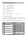
6.6 Configuring Memory
The default VxWorks configuration delivered by Wind River is for a RAD6000 with 128 MB of local
memory. Most RAD6000 boards have between 2 and 8 MB of RAM, so some changes will have to be made.
Before you can configure your memory, however, you must understand what features are configurable and
what restrictions are placed on the configuration.
There are four tables defined by the RAD6000 architecture that must reside in lower memory. These are the
Interrupt Vector Table, the Hash Allocation Table (HAT), the Page Frame Table (PFT), and the Translation
Control Word Table (TCW). In addition, some areas of lower memory are reserved for use by VxWorks.
Finally, you may also want to reserve some space in lower memory for use by your application program.
Let’s start by looking at the default VxWorks configuration and what a memory map based on that
configuration looks like. In the memory map shown in Table 2, all address ranges marked “unused” may
be used by the application program. However it is best to check with Lockheed Martin as to availability as
some device drivers also use these areas for buffer space. All other address ranges, however, are strictly
reserved and must not be modified directly by the application.
Starting Address
Ending Address
0x00000000
0x000000FF
Reserved
0x00000100
0x00001FFF
Interrupt Vector Table
0x00002000
0x000026FF
Unused
0x00002700
0x00002FFF
Reserved
0x00003000
0x0001FFFF
Unused
0x00008000
0x0000FFFF
Hash Allocation Table (HAT)
0x00010000
0x0001FFFF
Page Frame Table (PFT)
LOCKHEED M ARTIN FEDERAL SYSTEMS
6 Pulling It All Together - How to Build for Your Target
Starting Address
Ending Address
0x00020000
0x0002FFFF
Translation Control Word Table (TCW)
0x00050000
0x003FFFFF
VxWorks & Application
26
Table 2 Typical RAD6000 Memory Map (4 MB Memory)
The Interrupt Vector Table and those address ranges marked “Reserved” must reside at the addresses
shown in Table 2 and are therefore not configurable.
The HAT and the PFT are used by the memory management subsystem. The size of these tables depends on
the amount of local memory on your RAD6000 board and is therefore also not configurable. The starting
address of each of these tables, however, is configurable within certain limitations.
The TCW is used for DMA operations to map bus addresses to local addresses. Both the size and starting
address of the TCW are configurable. And, if you are not using DMA operations, you can set TCW_SIZE to
0 (zero) so that no space is reserved for a TCW at all.
6.6.1 Configuring the Hash Allocation Table (HAT)
The starting address for the HAT is defined by setting the HAT_ADRS variable in “config.h”. It must start
on a 32K boundary and its starting address must be greater than or equal to its size. Thus the starting
address for a 128K HAT must be equal to any 32K boundary at address 0x20000 or above.
The size of the HAT is dependent on the size of local memory and is therefore not user configurable. To
determine its size, take the size of local memory in bytes and divide it by 1024. However, the minimum HAT
size is 32K.
6.6.2 Configuring the Page Frame Table (PFT)
The starting address for the PFT is defined by setting the PFT_ADRS variable in “config.h”. It must start on
a 64K boundary and its starting address must be greater than or equal to its size. Thus the starting address
for a 512K PFT must be equal to any 32K boundary at address 0x80000 or above.
The size of the PFT is dependent on the size of local memory and is therefore not user configurable. To
determine its size, take the size of local memory in bytes and divide it by 256. The minimum PFT size is 64K.
6.6.3 Configuring the Translation Control Word Table (TCW)
The TCW is used for mapping local addresses to bus addresses for DMA operations. Each entry in the table
is 4 bytes long and maps an entire 4K page of addresses. To determine how large the TCW table should be,
first determine the largest I/O bus address that will need to be mapped for DMA. Dividing that address by
4096 will give you the number of pages of address space that need to be mapped, and, therefore, the number
of TCW entries that will be required. Multiplying the number of TCW entries by 4 gives you the size of the
TCW table in bytes. This formula, of course, can be simplified to dividing the largest I/O bus address to be
mapped by 1024.
LOCKHEED M ARTIN FEDERAL SYSTEMS
6 Pulling It All Together - How to Build for Your Target
Table Size
(in bytes)
TCW_SIZE Value
32 K
0x00008000
64 K
0x00010000
128 K
0x00020000
256 K
0x00040000
512 K
0x00080000
1M
0x00100000
2M
0x00200000
4M
0x00400000
27
Table 3 Supported TCW Sizes
That should be all there is to determining the size of the TCW. However, the RAD6000 architecture only
supports certain sizes. Therefore, once you have determined the size you need for the amount of address
space you intend to map, you must round it up to one of the sizes shown in Table 3. That table also
provides the value to be assigned to the variable TCW_SIZE in “config.h” in order to configure the TCW.
Once you have determined its size, you can easily determine its starting address, which must be on a
boundary equal to its size. Thus, a 128K TCW may be located at any address divisible by 128K. The
address is defined by setting the TCW_ADRS variable in “config.h”.
For more information on the TCW table and how it is used, please refer to Section 10.2.3.1 TCW Table
Management.
6.6.4 Locating VxWorks and Application Programs
Once you have determined the starting addresses and sizes for all of the system tables, you can define
where VxWorks and your application code and data should reside. This is done using two variables in
“config.h”: RAM_LOW_ADRS and LOCAL_MEM_SIZE. RAM_LOW_ADRS defines where VxWorks is to
be loaded and LOCAL_MEM_SIZE defines the maximum amount of local memory on your board. VxWorks
expects to be able to use all of the memory between RAM_LOW_ADRS and the top of memory
(LOCAL_MEM_SIZE).
Note that these variables also exist in “Makefile” and the values set in that file must match the values set in
“config.h”. Refer to the VxWorks documentation for more information on these variables.
6.6.5 Summary
Table 4 provides a summary of the variables defined in “config.h” that are used to configure memory.
Variable
Description
Legal Values
HAT_ADRS
Starting address of Hash
Allocation Table.
•
•
Must be on a 32K boundary.
Must be greater than or equal to the size of the
LOCKHEED M ARTIN FEDERAL SYSTEMS
6 Pulling It All Together - How to Build for Your Target
Variable
Description
28
Legal Values
HAT (LOCAL_MEM_SIZE / 1024).
Must be on a 64K boundary.
Must be greater than or equal to the size of the
PFT (LOCAL_MEM_SIZE / 256).
Determine the largest I/O bus address to be
mapped for DMA and divide it by 1024.
Refer to Table 3 and find the smallest value
greater than or equal to the above result.
Must reside on a boundary equal to its size.
PFT_ADRS
Starting address of Page
Frame Table.
•
•
TCW_SIZE
Size of Translation Control
Word Table in bytes.
•
TCW_ADRS
Starting address of
Translation Control Word
Table.
•
RAM_LOW_ADRS
Starting address of VxWorks
and application code and
data.
•
•
Must not conflict with system tables.
Variable must be set to the same value in both
“config.h” and “Makefile”.
LOCAL_MEM_SIZE
Amount of local memory in
bytes.
•
Must be equal to the amount of local memory
in bytes.
Variable must be set to the same value in both
“config.h” and “Makefile”.
•
•
Table 4 Memory Configuration Variables
6.7 Building VxWorks
Now the decisions are behind you for a while and you can build VxWorks for your computer. From the BSP
directory in your build directory, enter the following command:
make vxWorks.st (for VxWorks pre-Tornado versions)
or
make vxWorks
(for VxWorks Tornado versions )
Messages indicating ”no rules defined to build ...” usually mean that the environment variables are not set
(see Sections 2 and 3 ) or that an object file is referenced in “Makefile.RSCgreen” which has no source file
associated with it (check your additional objects defined in MACH_EXTRA or EXTRA_LIB).
If the build completes successfully, you will now have a new vxWorks[.st] file that contains the VxWorks
kernel configured for your board. In order to load it to your target you will have to convert it to a binary
image. If you are using the AdaMULTI toolset, this is done as follows:
elfToBin < vxWorks[.st] > vxWorks[.st].bin
If you are using IBM’s AIX XLC compiler, use the following command instead:
xcoffToBin < vxWorks[.st] > vxWorks[.st].bin
LOCKHEED M ARTIN FEDERAL SYSTEMS
6 Pulling It All Together - How to Build for Your Target
The file vxWorks[.st].bin can now be loaded on your target.
LOCKHEED M ARTIN FEDERAL SYSTEMS
29
7 Communicating over a Serial Port
30
7 Communicating over a Serial Port
Some RAD6000 boards use a RS–232 UART and have a standard 9–pin D–shell female connector. Others,
however, use an RS–422 UART with differential signals that can travel greater distances than the RS–232
signals. In these cases, the UART signals are usually connected to the backplane. Also, custom
configurations different than either of these options may be available.
This section discusses how to connect, configure, and use the serial device on your RAD6000, whichever
variety of UART happens to be on it.
This section also discusses the use of sendbin, a Lockheed Martin–provided tool that allows you to
download a VxWorks binary image to the target via the serial port.
7.1 Connecting a Serial Cable
As mentioned above, most RAD6000 boards use an RS–232 UART and have a standard 9–pin D–shell
female connector on the front panel of the board. Since most workstations have a 25–pin male serial
connector, an adapter is necessary to connect the serial ports. Also a null modem is required to interchange
transmit and receive signals. Figure 3 shows this set–up in graphical format.
9-pin to 25-pin
Adapter
PSA-32
9-pin Cable
Host
Null Modem
Figure 3 Typical Serial Connection with an RS-232 UART
Since RAD6000 boards with a RS–422 UART usually have UART signals connected to the backplane, they
will require a custom adapter. Again, a null modem is also required. Figure 4 shows this set–up in
graphical format.
Lockheed Martin will usually provide the custom serial adapter when Lockheed Martin is also providing
the backpanel (depending, of course, on the terms of the contract). However, for customers who buy only a
RAD6000 board and make their own backpanel, Lockheed Martin will provide the specs necessary to create
the custom serial adapter.
PSA-32
Custom
Adapter
Host
25-pin Cable
Null Modem
Figure 4 Typical Serial Connection with an RS-422 UART
7.2 Configuring the Serial Port and a Terminal Emulator
Once the UART is connected, the serial ports on the host and target computers must be configured to match
baud rates, parity bits, stop bits, and data bits. VxWorks and sendbin both set the target UART to 8 data
LOCKHEED M ARTIN FEDERAL SYSTEMS
7 Communicating over a Serial Port
31
bits, 1 stop bit, and no parity. The baud rate used by RAD6000s vary based on the specific model. To
summarize, configure your host UART with:
•
8 Data Bits
•
1 Stop Bit
•
No Parity
•
Baud Rate varies.
Basic communication to the target is accomplished via a terminal emulator such as tip or Kermit. Refer to
the documentation that comes with your terminal emulator to determine how to configure it.
7.3 Using sendbin to Download Target Software
Lockheed Martin provides boot software for RAD6000 breadboards to be used during application program
development. This boot software initializes the RAD6000’s memory and then accepts a load image from an
outside source. Since the one interface common to all RAD6000s and all host computers is the serial port,
the boot software uses that interface as a load path.
Binary load images are sent from the host to the target RAD6000 over the serial interface by a program
called sendbin. sendbin is a C program which uses standard system calls to interact with the serial port so
that it may be recompiled for any host running a UNIX–like operating system. Source code for sendbin is
provided to the user for this reason. sendbin has been compiled for AIX and Solaris platforms.
To compile sendbin for your host:
cc -o sendbin sendbin.c
sendbin does not configure the serial port that is being used for the download. It takes the values defined in
the operating system or the configuration defined by a terminal emulator such as tip or Kermit. See Section
7.2 for more information.
Whether or not a terminal emulator is used to configure the host’s serial port, one should be used during the
boot process. Lockheed Martin’s boot software will notify the user that it is ready to receive a load image by
sending characters over the serial port. Once these characters are received, the user can start sendbin.
To use sendbin, type the following command:
sendbin vxWorks[.st].bin load_address entry size tty
Where:
load_address is the address where VxWorks is to be loaded specified as a hexadecimal value
entry is the address of the program’s entry point specified as a hexadecimal value
size is the size of the program in bytes specified as a decimal value
LOCKHEED M ARTIN FEDERAL SYSTEMS
7 Communicating over a Serial Port
32
tty is an optional parameter specifying which serial port to use for AIX use /dev/tty format for Sun use
/dev/cua format.
The load_address and entry parameters must both be equal to the value of the RAM_LOW_ADRS
variable in “config.h”. The value of the size parameter can be easily determined by using the UNIX ls -l
command to determine the size of “vxWorks[.st].bin”. They tty parameter is only necessary if you are not
using the default serial port on your host workstation.
As an example, let’s say you want to load “vxWorks[.st].bin” using the “/dev/tty2” serial port. You first
need to look in “config.h” for the RAM_LOW_ADRS variable to find where the program is to be loaded.
Let’s say it is equal to 0x140000. Next, you will need to determine the size of the “vxWorks[.st].bin” file. For
our example, we’ll assume it’s equal to 638,040 bytes. The following command is used to load:
sendbin vxWorks[.st].bin 140000 140000 638040 /dev/tty2
7.4 Summary
Using the serial port to load VxWorks can be summarized as follows:
•
Connect host and target serial ports as described in Section 7.1.
•
Start terminal emulator with serial port parameters set as described in Section 7.2.
•
Reset target computer.
•
Wait for prompt from boot software.
•
When prompted, use sendbin to transfer binary load image to target as described in Section 7.3.
•
When transfer is complete, sendbin indicates ”Finished sending file”.
•
The boot software will then indicate ”Jumping to program” and will transfer execution to the
downloaded program.
•
If the VxWorks image does not use SLIP, you will see the VxWorks banner and prompt arrow.
•
If the VxWorks image does use SLIP, you will see ”nonsense characters” appearing in small groups
periodically. This is VxWorks trying to contact the other end of the point to point SLIP connection. See
Section 8 Using SLIP to Connect a RAD6000 to a Network, for more information.
7.5 Avoiding Common Pitfalls
Symptom
Problem
Solution
Unable to open serial port
with the terminal emulator.
Device is in use by another
task.
Terminate other task. Can not have Serial
Port and SLIP active at the same time.
Terminal Emulator is not
properly configured.
Ensure terminal emulator is installed
properly. (missing files or permissions ?)
Mismatch of serial port
parameters.
Ensure terminal emulator parameters match
the serial port parameters specified by the
host operating system.
RISCWatch holding
RAD6000.
From RISCWatch, enter ocs on.
Serial ports not connected or
Properly connect serial ports.
Prompt does not appear
after reset.
LOCKHEED M ARTIN FEDERAL SYSTEMS
7 Communicating over a Serial Port
Symptom
Problem
33
Solution
no null modem is attached.
No “Jumping to program”
message after sendbin, or
program crashes after
“Jumping to program”
message.
Mismatch of serial port
parameters.
Ensure terminal emulator is using the
correct parameters.
Extraneous characters sent to
target during load.
Do not touch keyboard while terminal
emulator is in the active window and
sendbin is executing.
Check tty parameters to ensure that <CR> is
not inserted before <LF> on outgoing
characters.
Bad binary load image.
No characters appear after
apparently successful
download.
Download “sendTst.bin” to verify
download procedure.
VxWorks using different baud Change baud rate of terminal emulator after
rate than boot software.
completion of download.
Incorrect SLIP IP address.
Modify “config.h” to include proper SLIP IP
address for target and host.
Table 5 Common Serial Communications Problems
LOCKHEED M ARTIN FEDERAL SYSTEMS
8 Using SLIP to Connect a RAD6000 to a Network
34
8 Using SLIP to Connect a RAD6000 to a Network
Serial Link Interface Protocol, or SLIP, is a layer of software that sits between the TCP/IP protocol stack and a
serial device driver. It allows the TCP/IP protocol to be used on a serial link, thus allowing a computer with
only a serial device (such as a RAD6000) to be placed on a network.
SLIP is provided as part of the AIX operating system that comes with IBM’s RISC System/6000 workstations.
However, UNIX–like operating systems for other platforms, such as Solaris on Sun workstations, do not
necessarily come bundled with SLIP. Products available provide SLIP for these platforms. See Section 8.6 for
a list of some of these products and what is known about using them.
This section will concentrate on configuring and using SLIP with AIX. Lockheed Martin has little experience
using SLIP products on other platforms, although some of our customers have used them successfully.
Hopefully even if you are using a platform other than AIX, you will be able to get an idea of the general
process from this section. Details, however, will have to come from the providers of the SLIP product you are
using.
8.1 Configuring SLIP for AIX
On the RAD6000 target board, the SLIP configuration is built into VxWorks. Only rebuilding the operating
system may change it. Refer to Section 6 to learn how to do this. Note that several of the SLIP parameters
built into VxWorks must match the SLIP parameters on your host workstation. This will be discussed in more
detail below.
For some of these steps, you will need to have root access. If you do not have root access to the workstation
you are using as a host, you will have to get your system administrator to perform these steps.
8.1.1 Attaching SLIP to the TCP/IP Protocol Stack
The first thing you have to do is create and configure a network interface and attach it to an existing serial
device. This requires root access. After logging into your host workstation as root, do the following steps:
1.
Use the following command to create and configure a network interface:
mkdev -c if -s SL -t sl -w slSN -a netaddr=HOSTADDR -a dest=TARGETADDR \
-a state=up -a ttyport=ttyTN -a baudrate=BAUD
Where SN is a number from 0 to 9 identifying your new network interface, HOSTADDR is your host’s IP
dotted decimal address, TARGETADDR is your target’s IP dotted decimal address, SN is a number from 0 to
9 identifying the serial device to be used, and BAUD is the baud rate (e.g., 9600).
TN must correspond to an existing tty device on your workstation. Most AIX workstations have two
serial ports named tty0 and tty1. Use the name corresponding to the serial port you plan to use for SLIP.
The value used for SN is up to you, but it must not be an existing serial link network interface. We
recommend that you always use the same value for SN that you use for TN. This way you should never
have a naming conflict.
LOCKHEED M ARTIN FEDERAL SYSTEMS
8 Using SLIP to Connect a RAD6000 to a Network
35
HOSTADDR, TARGETADDR, and BAUD must match the values given in the DEFAULT_BOOT_LINE
variable when you build VxWorks. See Section 6. for more information.
For example, to create a serial link network device named “sl1” to be attached to the serial port “tty1”
with a host TCP/IP address of 90.0.0.1 and a target TCP/IP address of 90.0.0.2 at 9600 baud, use the
following command:
mkdev -c if -s SL -t sl -w sl1 -a netaddr=90.0.0.1 -a dest=90.0.0.2 \
-a state=up -a ttyport=tty1 -a baudrate=9600
If you receive an error from this command, then it is most likely because:
2.
a.
You are not logged in as root. Log in as root and try again.
b.
The value chosen for SN corresponds to an existing network interface. Use a different value.
c.
The value chosen for TN does not correspond to an existing serial device. Use a different value.
Once you have successfully created a network interface, you must attach it to the chosen serial port. Do
this using the following command:
slattach ttyTN
Where TN is the same value given to TN in step 1. Using the same values as in the example above, you
would enter:
slattach tty1
Note that sometimes when the target computer is reset or turned off, the host computer’s serial link
connection will go down. If this happens, simply use the “slattach” command again to reconnect it.
8.1.2 Verifying or Modifying a SLIP Configuration
Once the SLIP connection is created, the “ifconfig” command can be used to verify or change the IP addresses,
network mask, and up/down status. Anyone can use this command to verify the parameters, but you must
have root access to modify them.
To verify them, merely enter:
ifconfig slSN
Where SN is the same value used for SN when the device was created.
To modify the parameters, first log in as root, and then enter:
ifconfig slSN HOSTADDR TARGETADDR NETMASK UPDOWN
Where SN, again, is the value used for SN when the device was created; HOSTADDR is the new host IP dotted
decimal address; TARGETADDR is the new target IP dotted decimal address; NETMASK is the TCP/IP network
mask (if unsure, use 255.255.255.0); and UPDOWN is either “up” if you want the device to be active, or “down”
if you want to disable the device.
LOCKHEED M ARTIN FEDERAL SYSTEMS
8 Using SLIP to Connect a RAD6000 to a Network
36
8.1.3 Detaching and Deleting a SLIP Device
To detach a serial link network device from a serial port, enter:
ifconfig slSN detach
Where SN is the value used for SN when the device was created.
To delete a serial link network device, enter:
rmdev -l slSN -d
Where SN, again, is the value used for SN when the device was created.
8.2 Creating .rhosts to allow remote operations
In order for you to be able to rlogin from your host into your target for the defined user you must tell the host
that the target is allowed to perform remote operations. In the home directory of the USER defined in the boot
line (as listed in Section 6.4) you must create a file called .rhosts. the .rhosts file must contain the name of the
Target board. A sample .rhosts file:
rsc
rsc2
target
8.3 Defining an IP Name for the Target
Since you probably don’t want to be referring to the target computer using its dotted decimal IP address all
the time, you should give the target an alphanumeric name. To do this, use your favorite editor to edit the
host file named “/etc/hosts” to add the following lines:
90.0.0.1
90.0.0.2
host
rsc
Each line associates a dotted decimal IP address with a name so that the name can be used in place of the IP
address. The values given above correspond to the examples in Section 8 above and in Section 6.4. If you
used different values when creating the serial link network device and when building VxWorks, you must
use those values here. That is, the values set in the DEFAULT_BOOT_LINE variable when VxWorks was
built must be the same values used in the “mkdev” command used to create the host serial link network
device and the same values used in the file “/etc/hosts”.
Next, you must define the target computer as ”trusted” when accessing the host. To do this, you must edit the
file named “.rhosts” in the home directory of the userid specified in the VxWorks DEFAULT_BOOT_LINE
variable. For more information on this variable, refer back to Section 6.4. All you have to add to this file is a
single line containing only the name of the target computer. Using the same values as in the other examples
in this document, merely add the following line:
rsc
LOCKHEED M ARTIN FEDERAL SYSTEMS
8 Using SLIP to Connect a RAD6000 to a Network
37
8.4 Using SLIP
Once you have SLIP configured on the host (which you should only have to do once) and have built a version
of VxWorks containing SLIP, you are ready to test it. To do this, first download VxWorks to the target board
as described in Section 7.3. Note that you will need to use a serial port for a terminal emulator and the
sendbin program during the download process. If you have SLIP attached to a serial port on your host, you
can not also use that serial port for terminal emulation and/or sendbin. One possibility is to detach the serial
port from SLIP while doing the download as described in Section 8.1.3. However, at Lockheed Martin we
have found that this sometimes leads to unreliable downloads and/or SLIP operation and can generally be a
hassle. Instead, if your host has more than one serial port, we recommend dedicating one of them to terminal
emulation and sendbin (we use tty0 or cua/a) and another for SLIP (we use tty1 or cua/b). We then connect
the serial cables from both ports to an A–B switch and attach the serial cable from the target to the other end of
the switch. This way, when the download has completed, you can merely flip the switch to go from using
terminal emulation to SLIP.
When the download has completed and a serial port with SLIP attached is connected from the host to the
target, try to ping the target. From the host, enter this command:
ping TARGET
Where TARGET is the IP address of the target (using the above examples, you would use 90.0.0.1). If this
works, try the command again, but this time use the IP name instead of the IP address (e.g., rsc). If either of
these did not work, see Section 8.7 for troubleshooting advice.
Once you have ping working, try to login to the target board. To do this, enter the following command from
the host:
rlogin TARGET
Where TARGET, again, is the IP name or address of the target board. If it worked, you should see the
following VxWorks interactive shell prompt:
->
If you don’t see that, refer to Section 8.7 for troubleshooting advice.
Once you have successfully logged in to the interactive shell on the target board, you can be sure that SLIP is
working properly.
8.5 Connecting AdaMULTI’s Debugger via SLIP
If you want to use AdaMULTI’s debugger over your SLIP connection, you must connect it within 60 seconds
from when you finished downloading VxWorks to the target board. This is due to a timeout in the remote
procedure call service in VxWorks. If more than a minute has passed since the download finished and you
want to use the AdaMULTI debugger, you must reset the target computer and reload VxWorks.
Once you have loaded VxWorks and have a SLIP connection between the host and the target, you can attach
the AdaMULTI debugger. To do this, bring up AdaMULTI if it is not already running by entering the
following:
LOCKHEED M ARTIN FEDERAL SYSTEMS
8 Using SLIP to Connect a RAD6000 to a Network
38
adamulti &
When the AdaMULTI Builder window appears, type the following in the text field to the right of the button
labeled “Remote”:
vxserv ipname –rsc, where ipname is the IP name of the RAD6000 target board.
Now click on the “Remote” button. This will bring up the main Debugger window that should contain the
source code for the program you are debugging. Refer to the Green Hills documentation for more information
on using the AdaMULTI debugger.
8.6 SLIP Products for Sun Workstations
This section is intended to help users of Sun workstations find SLIP products. However, Lockheed Martin
has limited experience with them. If you use any of these products, or other Sun workstation SLIP products,
we would appreciate hearing about your experiences with them to pass on to help other customers.
For the Solaris operating system there is a product called Morning Star. A trial copy can be retrieved from the
World Wide Web at http://www.morningstar.com. With this trial copy, the user gets a temporary license
that expires at the end of a trial period. After this, if interested in using the product, the user must obtain a
licensed copy. Please refer to their web site for more information.
8.6.1 Morning Star
We have successfully installed the Progressive Systems Morning Star product on a Sun Workstation. Using
Morning Star Version 1.4.1 using UNIX(r) System V Release 4.0 and Solaris 2.5.1 we were able to run slip on
the A or B serial ports on the Workstation. The rest of this section will explain how we configured our Sun
Workstation. The values given below for TARGET and HOST correspond to the variables in the examples in
Section 6.4. If anything listed in the following paragraphs is in conflict with what is found in the Morning
Star documentation, the Morning Star documentation should be presumed to be correct. Also, please let
Lockheed Martin know about the conflict so that we can make the required changes to our documentation.
8.6.1.1 Configuration
Install Morning Star as instructed in the “Morning Star PPP User Guide”. Once Morning Star has been
installed and licensed login into your machine as the root user. There are several files that were installed in
the /usr/lib/ppp directory and some additional files will need to be created. Fortunately Morning Star has
created example files of each of the required files. We strongly urge you to change the mode of these files from
owner read/write to owner read to prevent accidental modification. This can be accomplished by the
following:
cd /usr/lib/ppp
chmod -w *.ex
chmod -w Examples/*
8.6.1.1.1
DevicesA and DevicesB
Create a writable file called DevicesA from the Devices.ex file.
LOCKHEED M ARTIN FEDERAL SYSTEMS
8 Using SLIP to Connect a RAD6000 to a Network
39
cp Devices.ex DevicesA
chmod 666 DevicesA
Using your favorite editor add the following line to the file (SPEED is the speed of the of the device, 19200,
9600....):
Direct cua/a SPEED
Create a copy of the DevicesA file called DevicesB with the last line content line modified to use cua/b instead
of cua/a.
8.6.1.1.2
Filter
Create a writable file called Filter from the Filter.ex file.
cp Filter.ex Filter
chmod 644 Filter
Using your favorite editor: uncomment the lines starting with “internet gateway” and ending with “log
rejected” by deleting the leading “#” symbol and create a new default line as follows:
default bringup !ntp !3/icmp !5/icmp !11/icmp !who !route !60000/udp
keepup !send !ntp !3/icmp !5/icmp !11/icmp !who !route
8.6.1.1.3
SystemA and SystemB
Create a writable file called SystemA from the System.ex file.
cp System.ex SystemA
chmod 666 SystemA
Using your favorite editor add the following line to the file ( TARGET is the name of the target board, SPEED is
the speed of the of the device, 19200, 9600 ....):
TARGET Any;5 /dev/cua/a SPEED
Create a copy of the SystemA file called SystemB with the last line modified to use cua/b instead of cua/a.
8.6.1.1.4
pppSlipA and pppSlipB
Create a writable file with the “sticky bit” set called pppSlipA from the Examples/S65ppp.ex file. Setting the
mode to 7755 by “root” user allows any user to be able to run this script and even though the commands
inside of it that work with the serial ports are limited to use by the “root” user. Failure to set the “sticky bit”
will cause non root user to get error message indicating insufficient privilege to perform the requested action.
The following example shows the commands the root user will use to copy the file and set the “sticky bit”:
cp Examples/S65ppp.ex pppSlipA
chmod 7755 DevicesA
Using your favorite editor edit DevicesA and change the following lines from:
LOCKHEED M ARTIN FEDERAL SYSTEMS
8 Using SLIP to Connect a RAD6000 to a Network
40
#LOCAL=‘/usr/ucb/hostname‘
#REMOTE=”manatee”
to:
LOCAL=”Host”
REMOTE=”Target”
cp /usr/lib/ppp/SystemsA /usr/lib/ppp/Systems
cp /usr/lib/ppp/DevicesA /usr/lib/ppp/Devices
Create a copy of the pppSlipA called pppSlipB with the new lines using files SystemsB and DevicesB instead
of SystemsA and DevicesA. Lockheed Martin recommends that pppSlipA and pppSlipB be moved into
directory that is in all the users paths if desired so that user does not have to know where these files exist to
use them (i.e. the same place as kermit or sendbin are stored).
8.6.1.2 Starting and Stopping SLIP on Morning Star
In order to start the slip connection on serial port b enter the following command:
pppSlipB Start
The SLIP port will remain active until the Morning Star ppp daemon is terminated. Morning Star User Guide
states that the ppp daemon should be terminated with a kill -term command and NOT a kill -9 command
because it will leave your serial interfaces in an unknown state (See the pppd section on signals in the
Morning Star Users guide for additional information). Thus the recommended way to stop ppp is to use the
script by entering:
pppSlipB Stop
Serial port A works the same way as serial port b. SLIP on serial port A is started an stopped by using
“pppSlipA” instead of “pppSlipB”.
8.7 Avoiding Common Pitfalls
Symptom
Problem
Solution
No SLIP characters appear after
“Jumping to program” message.
Bad download process.
See Section 7.5.
VxWorks did not start network
automatically.
Check that the file “usrConfig.c”
contains the line:
#define INCLUDE_NET_INIT
SLIP characters appear, but can
not ping or rlogin target using
either the IP name or IP address.
SLIP is not active on the host.
Start SLIP on host and attach it to
serial port connected to target
using ifconfig or slattach.
or pppSlipA or pppSlipB
UART signals in addition to TX
and RX must be active to use SLIP.
Verify null modem against UART
appendix. Or wire control
LOCKHEED M ARTIN FEDERAL SYSTEMS
8 Using SLIP to Connect a RAD6000 to a Network
Symptom
Can ping, but can not rlogin.
41
Problem
Solution
Note: Which ones?
signals to always active.
Mismatch between host and target
regarding IP names and/or
addresses.
Check host files “/etc/hosts”
and “/etc/routes” against
VxWorks variable
“DEFAULT_BOOT_LINE” found
in “config.h”.
UART incorrectly connected.
Verify null modem against UART
appendix. Or wire control
signals to always active.
Boards with less than 2 MB of RAM Configure more memory, if
can not run interactive shell with
available. Otherwise use a direct
network.
serial connection to access
interactive shell, rather than
using SLIP.
Can ping or rlogin using IP
address, but not using IP name.
IP name is not defined on host.
Place IP address to IP name
mapping in host file
“/etc/hosts”.
Can rlogin, but can not use
VxWorks load command:
Target not trusted by host.
Place target IP name in “.rhosts”
file in home directory of user
identified by the VxWorks
variable
“DEFAULT_BOOT_LINE” found
in “config.h”.
Insufficient permission to access
files on host.
Use chmod to give access to object
files on host.
RPC timed out on target.
Connect AdaMULTI within 60
seconds of completion of
download.
ld < filename
Can rlogin from host, but
attempts to connect with
AdaMULTI give “RPC not
registered” message.
Can connect with AdaMULTI,
Unresolved references in file being
but can not use AdaMULTI “load loaded.
module” menu option.
Load objects being referenced
before loading current file.
Not enough memory.
Configure more memory, if
available, or unload unused
objects.
No error messages displayed.
Rlogin to target and retry load
module command.
No error messages displayed in
rlogin window, but error message
displayed in AdaMULTI window.
No error actually occurred, but
AdaMULTI timed out. Use
moduleShow to confirm
presence of new object file.
Disconnect and reconnect
AdaMULTI debugger to get file
LOCKHEED M ARTIN FEDERAL SYSTEMS
8 Using SLIP to Connect a RAD6000 to a Network
Symptom
Problem
42
Solution
into debugger.
LOCKHEED M ARTIN FEDERAL SYSTEMS
9 Connecting a Tornado Target Server
43
9 Connecting a Tornado Target Server
To make a VxWorks target ready for use with the Tornado development tools, you must start a target-server daemon
for that target on your host. One way to accomplish that is from the Tornado launcher. Once you become more familiar
with Tornado and its tools you might want start the server from the Sun command line. For more on that approach, see
section 3.6 Connecting a Tornado Server in the Tornado User’s Guide. For the remainder of this section, we will be
concerned with using the launcher method. To start the launcher execute the following command:
launch &
After your host and target are connected properly and you have downloaded a VxWorks binary image to the RAD6K,
you can now configure the target server to communicate to the target. Below are two examples configuring the RAD6K
target using ethernet and raw serial as the target server backend. Also included is a method for creating a virtual
console.
9.1 Creating a Virtual Console
Virtual I/O is a service provided jointly by the target agent and target server. It consists of an arbitrary number of
logical devices that convey application input or output through standard C-language calls. On the host, virtual I/O is
most easily connected to a dedicated display called the virtual console, under the control of the target server. This
method is used in the following two configurations. To automatically redirect the standard I/O to the virtual console a
file called windsh.tcl in your $HOME/.wind directory needs to be created. Tornado looks for this file each time you
execute an instance of the Tornado shell. If the file exists, the shell reads and executes its contents as Tcl expressions
before beginning to interact. You can use this file to automate any initialization steps you perform repeatedly. The
following example shell initialization file assigns standard input and output to the virtual console using channel 0, but
only if virtual channel 0 is not yet in use on the target:
# Set stdin, stdout, stderr and logging output to /vio/0 iff not already in use
if { [shParse {tstz = open ("/vio/0",2,0)}] != -1 } {
shParse {vf0 = tstz};
shParse {ioGlobalStdSet (0,vf0)} ;
shParse {ioGlobalStdSet (1,vf0)} ;
shParse {ioGlobalStdSet (2,vf0)} ;
shParse {logFdAdd (vf0)} ;
shParse {printf ("Std I/O set here!\n")}
} else {
shParse {printf ("Std I/O unchanged.\n")}
}
9.2 Creating an Ethernet Target Connection
After creating an ethernet network vxWorks image (see 6.5.1Network Connections) the target server will then connect
to the target agent using the default wdbrpc back end. This interface is the RAD6K’s fastest physical communication
channel. After downloading the binary vxWorks image to the RAD6K and the target agent has booted it sends the
message WDB READY to help test the connection. The following figure is typically seen in the serial window.
LOCKHEED M ARTIN FEDERAL SYSTEMS
9 Connecting a Tornado Target Server
44
Figure 5 VME Ethernet serial window example
After a successful boot the next step is to configure the target server. This is done by selecting Create from the Target
options from the Tornado launcher. Below is an example of an ethernet configuration. When this screen is filled out
press the Launch button to start the target server.
LOCKHEED M ARTIN FEDERAL SYSTEMS
9 Connecting a Tornado Target Server
45
same name as
in bootline and
/etc/hosts
path to
vxWorks
image
select default
for network
backend
click for
debug
Figure 6 Create Ethernet Target Example
Following a successful start the following messages are displayed in the Logfile Viewer window:
LOCKHEED M ARTIN FEDERAL SYSTEMS
9 Connecting a Tornado Target Server
Figure 7 Successful Logfile Example
At this point, the target server and agent are connected and the buttons at the bottom of the Tornado Launcher can
now be used to select the Tornado tools - Windshell, Browser, or WindConfig.
LOCKHEED M ARTIN FEDERAL SYSTEMS
46
9 Connecting a Tornado Target Server
47
Figure 8 Launcher Window Example
9.3 Creating a Raw Serial Target Connection
After creating a raw serial image (see 6.5.2 Serial-Line Connections) the target server will then connect to the target
agent using the wdbserial backend. This is the most compact image since the VxWorks network code is not needed and
allows for system-mode as well as task-mode debugging. After the binary image has been downloaded to RAD6K and
booted the target agent sends the WDB READY message over the serial line. Below is an example of a serial window
after the raw serial image has booted.
LOCKHEED M ARTIN FEDERAL SYSTEMS
9 Connecting a Tornado Target Server
48
Figure 9 TTY Raw Serial Example
Note: At this point, your terminal emulation software must be disconnected so that it does not interfere with the target
server and agent communication.
After a successful boot the next step is to configure the target server. This is done by selecting Create from the Target
options from the Tornado launcher. Below is an example of a raw serial configuration with a baud rate of 38400. When
this screen is filled out press the Launch button to start the target server.
LOCKHEED M ARTIN FEDERAL SYSTEMS
9 Connecting a Tornado Target Server
select
wdbserial
for raw
serial
49
name of
serial port
select baud
rate of
UART and
serial port
(9600 for
VME)
Figure 10 Create Raw Serial Target Example
If you forgot to disconnect your terminal emulation program you might see a message like the following in the Logfile
viewer window:
LOCKHEED M ARTIN FEDERAL SYSTEMS
9 Connecting a Tornado Target Server
50
Figure 11 Logfile Example Showing Bad Serial Connection
Otherwise, you will see a successful set of messages as shown in the Figure 7 Successful Logfile Example. At this
point, the target server and agent are connected and the buttons at the bottom of the Tornado Launcher can now be
used to select the Tornado tools - Windshell, Browser, or WindConfig as shown in Figure 8.
LOCKHEED M ARTIN FEDERAL SYSTEMS
9 Connecting a Tornado Target Server
9.4 Connecting Green Hills Multi to the Target Server
Connect
to
Target
Server
Figure 12 Connecting Multi to Target Server
LOCKHEED M ARTIN FEDERAL SYSTEMS
51
10 How to Take Advantage of RAD6000 Features
52
10 How to Take Advantage of RAD6000 Features
This section discusses features of the RAD6000 processor and how an application program can use VxWorks
services to take advantage of these features. The first part provides an overview of the RAD6000 architecture. It is
followed by a discussion of the functions provided by the VxWorks RAD6000 Board Support Package. Note that,
wherever possible, the standard VxWorks BSP templates were used in implementing these functions. In these cases,
you will be referred to the VxWorks documentation.
10.1RAD6000 Processor Architecture Overview
As mentioned in a previous section, the RAD6000 is a radiation–hardened version of IBM’s RSC processor that was
the precursor to the PowerPC. It is a 32–bit, pipelined, RISC processor capable of executing up to four instructions
each cycle. This section will provide a brief overview of some of the features that are useful for developers to
understand. For a more complete discussion of the RAD6000 processor and its instruction set architecture, please
refer to the POWER Processor Architecture.
Note that throughout this section, bits are numbered using IBM notation where bit 0 refers to the most significant bit.
Also, the RAD6000 stores data in memory such that the most significant byte always has the lowest address.
10.1.1 Registers
The RAD6000 has 32 fixed–point general purpose registers (GPRs), each of which is 32–bits wide; 32 floating–point
registers (FPRs), each of which is 64–bits wide; and 9 special purpose registers, each of which is 32–bits wide.
Detailed descriptions of these registers can be found in the POWER Processor Architecture document. This section
will provide a brief overview of the function of some of these registers.
The contents of all of these registers can be viewed during operational debug by using either the AdaMULTI
debugger or IBM’s RISCWatch tool, described in Section 11.
10.1.1.1 RSC Address Space and Segment Registers(SR)
Within the RSC there are four main address spaces. They are:
• Local Memory (includes RAM, EEPROM and SUROM)
• IOCC
• EICR
• IO (VME or PCI)
There are 16 special purpose registers used to these address spaces. They are called segment registers. These registers
determine what type of address space is being accessed (e.g. – memory vs. I/O, IOCC space). Each of the four address spaces
is accessed using a unique segment register that is configured to properly access that particular address space. Bits 0 and 1
are system control bits defining system state. Bits 2 to 11 select system facilities such as the IOCC. Bits 12, 13 and 26 mediate
IOCC operationsm while bit 24 provides access to IOCC facilities. Bits 14 to 23 and bit 27 are reserved, and bits 28 to 31 are
used as an address extension for the address.
Address Space
Segment Register
Segment Register value
LOCKHEED M ARTIN FEDERAL SYSTEMS
10 How to Take Advantage of RAD6000 Features
Local Memory
EICR
IO (VME or PCI)
IOCC
0 and 0xF
0xD
0xC
0xE
53
0x00000000
0x80000000 (I/O = 1)
0x82000000 (I/O = 1, BUID = 0x20)
0x82000080 (I/O = 1, BUID = 0x20, IOCC = 1)
Table 6 Segment Register Values for RSC Address Space
The other segment registers can be configured to access other address spaces such as AMB, PLASMA, and QHSS.
.
Effective Address
0…3
4 …………………… 31
Segment Reg. 0 .. 15
0 …………………… 27
Bits 0..27 determine
type of memory or
I/O space addressed
28..31
0…3
4 …………………… 31
Real Address
Figure 13 Converting effective address to real address
Example
temp = *0x70089ad0;
/* C */
-> l
# assembler load instruction
r3,0x14(r4)
when
and
r4 = 0x70089abc
sr7 = 0x82000009
has an effective address of 0x70089ad0 and
accesses address 0x90089ad0 on the I/O
bus.
It's the I/O bus because of the 0x82000000
in the segment register and it's 0x90000000
because of the lower nibble of the segment
register.
LOCKHEED M ARTIN FEDERAL SYSTEMS
10 How to Take Advantage of RAD6000 Features
54
10.1.1.2 Generating an RSC Interrupt
MSR reg. (External Enable bit ) *
RSC
Interrupt
IOCC Config. Reg. (Master Enable bit) *
External Interrupt Status Reg. (EIS0)
(EIS0) **
External Interrupt Mask Reg. (EIM0) *
External Interrupt Status Reg. (EIS1)
(EIS1) **
External Interrupt Mask Reg. (EIM1) *
Interrupt Request Reg. (IRR)
(IRR) **
Decrementer (EIS BID)
Interrupt Enable Reg. (IER) *
End of Interrupt Reg.
(must be read to receive
subsequent interrupts )
External Interrupt 1 – 15 (Active low)
Memory Error (EIS BID)
Early Power Off (EIS BID)
* 1 = Enable, 0 = Mask
Interrupt
Misc.
Interrupt
Request
Reg.
Reg.
(MIR)
(IRR)**
** 1 = Interrupt
Channel Check
Bus Timeout
External Interrupt 0 (Active low)
Figure 14 Generating RSC Interrupts
LOCKHEED M ARTIN FEDERAL SYSTEMS
10 How to Take Advantage of RAD6000 Features
10.1.1.3 Address Spaces
10.1.1.3.1 Memory Address Space (RAM and SUROM)
Effective Address 0xxxxxxx
Segment Reg = 00000000
Segment Reg. 0xF Effective Address Fxxxxxxx
Segment Reg = 00000000
Segment Reg. 0
Typical Usage:
00000000
Unused by OS, SUROM Status Area
00000100
Interrupt Vector Table
00002000
Unused by OS, SUROM Workspace
00002700
bootline, exc panic
00003000
Unused by OS, used for I/O Driver Data
00008000
HAT (for a min configuration)
00010000
PFT (for a min configuration)
00020000
TCW (32 K)
00050000
VxWorks & User Code and Data
___________
_
LIO RAM Size (S1) = 00400000
00400000
End of populated memory (4MB typical)
08000000
End of addressable real memory (128MB)
___________
_
fff00000
SUROM
___________
_
LIO SUROM Size (S3) = 00010000
fff10000
End of populated SUROM (64KB typical)
fff80000
End of populated SUROM (128KB max)
10.1.1.3.2 IOCC Address Space (RAD6000 & LIO Regs)
Segment Reg. 0xE
Effective Address 0xExxxxxxx Segment Reg = 82000080
Usage:
00000000
LIO Registers
00000400
Primary PCI
00010000
RAD6000 Registers
00500000
End of utilized addresses
10.1.1.3.3 EICR Address Space (RAD6000 Interrupt Regs)
LOCKHEED M ARTIN FEDERAL SYSTEMS
55
10 How to Take Advantage of RAD6000 Features
Segment Reg. 0xD
56
Effective Address 0xDxxxxxxx Segment Reg = 80000000
Usage:
00000000
RAD6000 Registers
00000040
End of utilized addresses
10.1.1.3.4 PCI I/O Address Space
Segment Reg = 82000000
Segment Reg. 0xC
Effective Address 0xCxxxxxxx
Segment Reg. n
Effective Address nxxxxxxx
Segment Reg = 8200000m
(where n is segment 1 to b, and m is between 1 and f)
Usage:
00000000
LIO and RAD6000 Registers (1K)
00000400
PCI Primary I/O Space
Registers on PCI chips are mapped here
___________
_
LIO RAM Size (S1) = 00400000
00400000
End of PCI Primary PCI Space (Typical)
___________
_
LIO Base Address (BA2) = C0000000
c0000000
Start of Extended PCI I/O Space (Typical)
Some chips, such as PLASMA, have address ranges here
ffffffff
End of Extended PCI I/O Space
10.1.1.3.5 PCI Memory Address Space
Segment Reg = 82000000
Segment Reg. 0xC
Effective Address 0xCxxxxxxx
Segment Reg. n
Effective Address nxxxxxxx
Segment Reg = 8200000m
(where n is segment 1 to b, and m is between 1 and f)
Usage:
00000000
RAD6000 RAM for 1p DMA
___________
_
LIO RAM Size (S1) = 00400000
00400000
End of populated memory (4MB typical)
00400000
PCI Memory Space
Smaller address ranges are mapped here such as SuMMIT RAM
10000000
PCI Memory Space
Larger address ranges are mapped here such as AMB & PLASMA
___________
_
LIO Base Address (BA2) = C0000000
LOCKHEED M ARTIN FEDERAL SYSTEMS
10 How to Take Advantage of RAD6000 Features
Usage:
C0000000
End of PCI Memory Space (Typical)
10.1.1.3.6 EICR Addressable Registers
00000000
EIM0 (External Interrupt Mask 0..31)
00000004
EIM1 (External Interrupt Mask 32..63)
Bit 0 is msb, bit 31 is lsb, when a bit is 0 then the corresponding interrupt level
is masked from interrupting the RAD6000 instruction flow. When a bit is 1,
then the corresponding interrupt level will interrupt the RAD6000 when the
interrupt becomes set in the EIS register.
00000008
EESR (External (DMA) Error Status)
0000000C
EEAR (External (DMA) Error Address)
External errors detected by the RAD6000 are reported to the EESR. The
address causing the error is reported to the EEAR. The first occurrence of the
error is kept in the registers until they are read. Once read they may be
updated by the hardware.
EESR [3] = AD
DMA Address Exception (out of range)
EESR [4] = UD
Uncorrectable ECC error on DMA
EEAR [0..7]
Syndrome of from ECC of erroneous 8-byte word
EEAR [8..31]
Effective address of erroneous 8-byte word divided by 8
00000010
EIS0 (External Interrupt Status)
00000014
EIS1 (External Interrupt Status)
External interrupts to the RAD6000 are reported to the EIS so that the external
interrupt handler can determine which interrupt level is active.
00000018
MESR (Machine Check Error Status)
0000001C
MEAR (Machine Check Error Address)
Memory errors detected by the RAD6000 are reported to the MESR. The
address causing the error is reported to the MEAR. The first occurrence of the
error is kept in the registers until they are read. Once read they may be
updated by the hardware.
Note: A machine check clears the Machine Check Enable bit (ME) in the
Machine State Register (MSR). Software must set it back to a one to enable the
next machine check. The occurrence of a machine check condition while this
bit is clear will result in a Checkstop (RAD6000 stops execution).
MESR [0] = DTM
MESR [1] = LS
MESR [3] = AE
MESR [4] = SR
MESR [5] = UE
MEAR [0..7]
MEAR [8..31]
00000020
Error occurred while in diagnostic mode
Processor load or store (not DMA)
Address exception (out of range)
Attempted store to SUROM
Uncorrectable ECC error
Syndrome of from ECC of erroneous 8-byte word
Effective address of erroneous 8-byte word divided by 8
DEB (Decrementer EIS Bit ID)
The RAD6000 decrementer interrupts when it counts down to zero and rools
over to 0xffffffff. It defaults to exgternal interrupt level 0, but can be moved to
LOCKHEED M ARTIN FEDERAL SYSTEMS
57
10 How to Take Advantage of RAD6000 Features
58
another level by writing to this register. The value of this register is the
interrupt level used by the decrementer. Valid values are 0 to 63.
00000024
MEEB (Memory Error EIS Bit ID)
The RAD6000 reports machine check (memory) errors and single bit errors as
external interrupts when in diagnostic mode. The value of this register is the
interrupt level used. Valid values are 0 to 63.
00000028
SBSR (Single Bit Error Status)
0000002C
SBAR (Single Bit Error Address)
Single bit (correctable) memory errors detected by the RAD6000 are reported to
the SBSR. The address causing the error is reported to the SBAR. The first
occurrence of the error is kept in the registers until they are read. Once read
they may be updated by the hardware.
SBSR [0] = CE
SBAR [0..7]
SBAR [8..31]
00000030
SCCR (Storage Control Reg)
Operation in diagnostic mode results in the generation of an external interrupt
for memory related machine check errors and for single bit errors. Cache and
ECC checking can be disabled for testing purposes.
SCCR [0]
SCCR [2..3]
SCCR [4]
SCCR [5]
SCCR [6]
SCCR [7]
00000034
Correctable ECC error
Syndrome of from ECC of erroneous 8-byte word
Effective address of erroneous 8-byte word divided by 8
Diagnostic Mode
Invert address bits 6..7 respectively
Disable RAD6000 cache
Disable extenal cache (not used)
Invert address parity on reads
Disable ECC checking on reads
EPOWEB (Early Power Warning EIS Bit ID)
The RAD6000 has an external interrupt line reserved for power-off warnings.
It is usually tied inactive. If used (possibly for other purposes) it can be
mapped to any interrupt level. Valid values are 0 to 63.
10.1.1.3.7 IOCC Addressable Registers
00400010
Configuration Reg – VME configuration
The IOCC design allows variations and performances that optimize its usage across
multiple machine environments. This register establishes the specific personalization.
CR[0] = ME
Master Enable – must be set to receive any interrupt
CR[1]
Reserved
CR[2..3]
Clock Control – The RBI interprets this field depending on the setting
of bit 14. When bit 14 is zero (configuration data applies to PIO
operations), this field represents “turbo” clock control. When the value
stored is ’01’ the CPU runs at the oscillator frequency divided-by-2
(usually 20 MHz), overriding the value in the Clock Control field (bit
15) (Bread Board only). The other values of ‘00’ and ‘1x’ have no effect;
the CPU frequency stays as defined by bit 15. On the EM/Flight
LOCKHEED M ARTIN FEDERAL SYSTEMS
10 How to Take Advantage of RAD6000 Features
configuration, the system clock frequency is controlled as specified in
the description for bit 15.
When bit 14 is a one (configuration data applies to 3P DMA
operations), the RBI takes this field as the most significant bits of the
VMEbus address modifier code for third party DMA. In the RVIO
architecture, the processor controls the VMEbus until the PIO transfer
completes, regardless of whether another device wants the bus.
00400010
CR[4..5]
AML – used as the least significant two bits of the VMEbus modifier
code for third party DMA or PIO depending on the setting of bit 14
CR[6-7]
LIM – used as third party DMA data width when bit 14 is a one.
CR[8]
Reserved – must be 0
CR[9..11]
TCW Table size - in the RVIO, the card ID and VMEbus
Slave/Address Control register are implemented such that the TCW
extent cannot be exceeded. Therefore, the RBI ignores this field.
CR[12]
Reserved
CR[13]
Bus hold/ 3P K bit - When bit 14 is a zero, this bit is used by the RVIO
to retain ownership of the VMEbus between transfers (bus hold). When
bit 14 is a one, the RBI passes this bit on to the IOC as the privilege bit
for third party DMA.
CR[14]
PIO/ 3P Select – The RBI uses this bit to define whether the AML and
LIM bits (bits 4 through 7) are being set for PIOs (when bit 14 = 0 ) or
third party DMA (when bit 14 = 1).
CR[15]
Clock Control – The RBI uses this bit with bits 2 and 3 to control the
system clock rate with 0 (reset state) indicating quarter speed
(divide-by-8, 5 MHz) and 1 indicating half speed clock (divide-by-4,
10 MHz) for the Bread Board. For EM/Flight, 0 indicates divide-by-16
(2.5 MHz) and 1 indicates divide-by-8 (5 MHz) if bits 2-3 = 00 or 1x. If
bits 2-3 = 01 then 0 indicates divide-by-4 (10 MHz) and 1 indicates
divide-by-2 (20 MHz).
CR[16-31]
Reserved
Configuration Reg – ASCM/LIO configuration
The IOCC design allows variations and performance that optimize its usage across
multiple machine environments. This register establishes the specific personalization.
This register is set up by hardware and SUROM code.
CR[0] = ME
Master Enable – must be set to receive any interrupt
CR[1]
Reserved
CR[2..3]
Master PCI Bus Timeout Error Control:
00 – 256 PCI Clock Cycles
01 – 512 PCI Clock Cycles
10 – 1024 PCI Clock Cycles
11 – 2048 PCI Clock Cycles
CR[4]
PCI Bus Timeout Error Checking Disable – when this bit is set to a one
the LIO disables checking for PCI Bus Timeouts and PCI Data Phase
Timeout errors.
LOCKHEED M ARTIN FEDERAL SYSTEMS
59
10 How to Take Advantage of RAD6000 Features
CR[5]
Error Holdoff Function Disable – When this bit is to a one the Error
Holdoff Function is disabled.
CR[6]
RSC I/O Bus Data Parity Checking Disable – When this bit is set to a
one the LIO ignores parity errors detected on the RSC_I/O_DA_BUS.
CR[7]
Wrap Enable – this bit determines whether IOCC Mode PIOs to
internal architected registers should be handled internally or
externally via the PCI Bus for diagnostic purposes.
0 – PIO executed internally
1 – PIO executed as PCI Bus operations (writes are subject to same
restrictions as external PCI masters).
CR[8]
Reserved
CR[9..11]
TCW Table size - in the RVIO, the card ID and VMEbus
Slave/Address Control register are implemented such that the TCW
extent cannot be exceeded. Therefore, the RBI ignores this field.
CR[12-14]
Reserved
CR[15]
DMA Master Enable – This bit shall be used as master enable for first
party DMA transfers.
0 = 1P DMA disabled for all channels
1 = 1P DMA not globally disabled, individual channel enables
controlled by DMA Enables register.
CR[16-31]
Reserved
00400024
TCW Anchor Reg
00400040
I/O Limit Reg
004y0060*
Channel Status Reg – VME bus master / ASCM LIO configurations
CSR[0-3]
Control and Status – This field contains control and status and may be
set by both the control program or the IOCC. Values between x’0-3’ are
control channel operations while values between x’4-15’ are error
codes. Bit 3 is controlled by channel enable and disable commands (see
reg. 004y0070 below).
004y0060*
CSR[4]
for
DMA Slave Flag – this bit is set to a value of 0 to personalize a channel
bus master data transfer operation.
CSR[5]
Reserved
CSR[6]
Prevent Channel Disable on Error
CSR[7-11]
Reserved
CSR[12-15]
Buffer Number
CSR[16-23]
Authority Mask
CSR[24-31]
Reserved
Channel Status Reg – VME bus slave
CSR[0-3]
Control and Status – This field contains control and status and may be
set by both the control program or the IOCC. Values between x’0-3’ are
control channel operations while values between x’4-15’ are error
codes. Bit 3 is controlled by channel enable and disable commands (see
LOCKHEED M ARTIN FEDERAL SYSTEMS
60
10 How to Take Advantage of RAD6000 Features
61
reg. 004y0070 below).
CSR[4]
CSR[5]
004y0064*
Reserved
System Memory – this bit selects whether system memory or bus
memory is to take part in a DMA slave transaction. 1 = DMA slave
transfers to system memory and 0 = DMA slave transfers to bus
memory.
CSR[6]
Enable Terminal Count Flag
CSR[7]
Direction Flag – this bit selects the direction of a DMA slave transfer. 0
= transfer data from memory to the I/O device, 1 = transfer data from
the I/O device to memory.
CSR[8-19]
Next Tag Field
CSR[20-31]
transfer.
Length Count Field – this field contains a length count for the data
DMA Address Reg – VME bus master
N/A
004y0064*
DMA Address Reg – VME bus slave
This register contains the VME bus memory address for the DMA slave operation.
004y0068*
Channel Buffer Invalid Reg
N/A - this register exists only for buffered mode implementations
004y0070*
Channel Enable(load)/Disable(store)
This register allows system initiation and suspension of DMA slave and bus master
operations. The enable command initializes a channel to accept requests by changing
the channel status field in the Channel Status register from the disabled (B’00x0’) state to
the enabled (Bx’00x1’) state. This command is coded as a load instruction. The disable
command initializes a channel to disables operation for a particular channel by
changing the channel status field in the Channel Status register from the enabled
(B’00x1’) state to the disabled (Bx’00x0’) state. This command is coded as a store
instruction (data is ignored).
004y0078*
DMA Slave Buffer Flush
N/A - this register exists only for buffered mode implementations
00400080
Interrupt Enable Reg
(IER)
00400084
Interrupt Request Reg
(IRR)
00400088
Misc Interrupt Reg
0040008C
End Of Interrupt Reg
(EOI)
Following presentation of an I/O interrupt to the system External Interrupt Source (EIS)
register, the IOCC automatically masks off that interrupt so the presentation is only made
once. An end of interrupt command re-enables this mask, causing any active interrupts
to be presented to the system EIS register. On a store the data is ignored, on a load the
data is indeterminate. This command should be issued at the end of all Interrupt Service
Routines (ISR).
00400004
Ack Interrupt, VMEbus SYSFAIL Interrupt
LOCKHEED M ARTIN FEDERAL SYSTEMS
10 How to Take Advantage of RAD6000 Features
00410004
Ack Interrupt, VMEbus IRQ1 Interrupt
00420004
Ack Interrupt, VMEbus IRQ2 Interrupt
00430004
Ack Interrupt, VMEbus IRQ3 Interrupt
00440004
Ack Interrupt, VMEbus IRQ4 Interrupt
00450004
Ack Interrupt, VMEbus IRQ5 Interrupt
00460004
Ack Interrupt, VMEbus IRQ6 Interrupt
00470004
Ack Interrupt, VMEbus IRQ7 Interrupt
00480000
SUROM Remap Reg
00480004
Real-Time Interrupt Control Reg (Aux clock)
00490004
VMEbus Slave A32 Control
004A0004
VMEbus Slave A24 Control
004B0004
VMEbus Interrupt Register
00C00000
TCW Table, 1 MB of memory mapped to I/O space by TCW Anchor Register
62
* y=0-f
10.1.1.4 Machine State Register (MSR)
The MSR is arguably the most important register to the RAD6000, as it defines the operational state of the processor.
It is generally not of interest to application program developers as its state is maintained by VxWorks. However, an
understanding of it is necessary while developing and debugging start–up code, interrupt handlers, and device
drivers. It can also help in tracking down unexpected problems.
Table 7 provides a list of all of the bits of the MSR and their valid values. You will probably want to refer back to
this table in later sections as the effects of these bits on various RAD6000 features is explained.
Bit(s)
Name
0–15
Reserved
16
External Interrupt Enable (EE)
17
18
19
20
Value
Program State (PR)
Floating–Point Available (FP)
Machine Check Enable (ME)
Floating–Point Exception Interrupt Enable
(FE)
Result
0
External interrupts are disabled.
1
External interrupts are enabled.
0
Privileged instructions are allowed.
1
Privileged instructions are invalid.
0
Floating–point instructions are invalid.
1
Floating–point instructions are allowed.
0
Machine check interrupts are disabled.
1
Machine check interrupts are enabled.
0
Program interrupts for floating–point
enabled exception are disabled.
1
Program interrupts for floating–point
LOCKHEED M ARTIN FEDERAL SYSTEMS
10 How to Take Advantage of RAD6000 Features
Bit(s)
Name
Value
63
Result
enabled exception are enabled.
21–23
Reserved
24
Alignment Check (AL)
25
26
27
28-31
Interrupt Prefix (IP)
Instruction Relocate (IR)
Data Relocate (DR)
0
Alignment checking is disabled.
1
Alignment checking is enabled.
0
The interrupt table is located at 0x00000000.
1
The interrupt table is located at 0xFFF00000.
0
Instruction address translation is disabled.
1
Instruction address translation is enabled.
0
Data address translation is disabled.
1
Data address translation is enabled.
Reserved
Table 7 Machine State Register
10.1.2 Interrupts
The RAD6000 uses a table in memory that is 0x1F00 bytes long to determine how to respond to an interrupt. Each
entry in the table is 0x100 bytes long and corresponds to one of the available interrupt types. When the processor
takes an interrupt of a given type, it branches directly to the address associated with that entry.
This interrupt table can be located in either ROM space or RAM space, depending on the state of the Interrupt Prefix
(IP) bit (bit 25) of the Machine State Register (MSR). If this bit is set to 1, the interrupt table is in ROM space and
starts at address 0xFFF00000. If it is set to 0, the interrupt table is in RAM space and starts at address 0x00000000.
Note that the first 0x100 bytes of this table are not used by the processor itself, although the VxWorks operating
system may use some of these addresses. Table 8 shows the address offset from the beginning of the table for each
type of interrupt. The remaining addresses (0x900 - 0x2000) are reserved and must not be used.
Offset
Type
Description
0x100
System Reset Interrupt
Executes in response to RAD6000 hardware reset.
0x200
Machine Check Interrupt
Executes in response to uncorrectable memory errors only if
the Machine Check Enable (ME) bit (bit 19) of the MSR is set to
1.
0x300
Data Storage Interrupt
Executes in response to errors during a data load or store,
such as I/O access errors or memory protection violations.
0x400
Instruction Storage Interrupt Executes in response to errors during an instruction fetch,
such as a memory protection violation.
0x500
External Interrupt
Executes in response to an external interrupt.
0x600
Alignment Interrupt
Executes in response to an unaligned data access only if the
Alignment Check (AL) bit (bit 24) of the MSR is set to 1.
0x700
Program Interrupt
Executes in response to unrecognized, invalid, or privileged
LOCKHEED M ARTIN FEDERAL SYSTEMS
10 How to Take Advantage of RAD6000 Features
Offset
Type
64
Description
instructions.
0x800
Floating Point Unavailable
Interrupt
Executes in response to the execution of any floating–point
instruction only if the Floating–Point Available (FP) bit (bit 18)
of the MSR is set to 1.
Table 8 Interrupt Offsets and Descriptions
When the processor takes an interrupt, it performs the following steps:
1.
Places the address of the current or next instruction, depending on the type of interrupt, into SRR0.
2.
Places interrupt–specific information into bits 0–15 of SRR1.
3.
Places a copy of bits 16–31 of the MSR into bits 16–31 of SRR1.
4.
Sets certain bits of the MSR to specific states, depending on the type of interrupt.
5.
Branches to the entry in the interrupt table corresponding to the type of interrupt.
VxWorks provides default interrupt handlers for all of these interrupt types and you will probably not need to
replace them. If you do decide to replace them, refer to the POWER Processor Architecture document for details on
each type of interrupt processing.
However, you may want to write your own interrupt handlers for external interrupts. The Board Support Package
you are using will come with default interrupt handlers for all of the attached external devices, such as the serial
bus, VMEbus, etc. However, you may want to replace these and/or write interrupt handlers for external devices you
attach to your RAD6000. The RAD6000 supports up to 16 external interrupts, mapped to one of 64 interrupt levels.
When an External Interrupt occurs, the processor branches to offset 0x500 of the interrupt table as described above.
This handler saves the machine context and then reads the External Interrupt Status (EIS) register to determine
which external interrupt occurred. If an interrupt handler for that interrupt is installed, it is then called as a
subroutine from the External Interrupt handler. When that handler returns, the External Interrupt handler restores
the machine context and returns to the interrupted code.
10.2The RAD6000 Board Support Package
This section describes the functions provided with all RAD6000 BSPs. Some BSPs support additional functionality,
as appropriate for that board. These functions, if available, are documented in an appendix to this document.
10.2.1 External Interrupts
If you are familiar with VxWorks, you are probably familiar with the VxWorks routine intConnect, which is
normally used to attach an interrupt service routine (ISR) to an external interrupt. On the RAD6000, however, that
routine is reserved solely for VME–based BSPs. Other BSPs use the function sysIntConnect. This routine expects
the interrupt level and the address of the ISR to be given as parameters.
Ada Syntax:
LOCKHEED M ARTIN FEDERAL SYSTEMS
10 How to Take Advantage of RAD6000 Features
65
function sysIntConnect (
intLevel
: integer
functionPtr : system.address)
return Status;
C Syntax:
STATUS sysIntConnect (
int
intLevel,
void *Handler);
N.B. If you are using this routine to connect your ISR to an external interrupt
you must read the IOCC End of Interrupt register at the end of your ISR to
receive subsequent interrupts.
C Syntax:
temp = *IOCC_EOI;
Ada Syntax:
temp := rscFns.IOCC_End_Of_Int;
To disable an external interrupt, use the function sysIntDisable, passing in the interrupt level as a parameter.
Ada Syntax:
function sysIntDisable (
intLevel : integer)
return Status;
C Syntax:
STATUS sysIntDisable (
int intLevel);
To enable an external interrupt, use the function sysIntEnable passing in the interrupt level as a parameter.
Ada Syntax:
function sysIntEnable (
intLevel : integer)
return Status;
C Syntax:
STATUS sysIntEnable (
int intLevel);
10.2.2 Serial Port I/O
The serial I/O device driver, located in the file “tyCoDrv.c” in your BSP directory, follows the standard VxWorks
conventions. During initialization, VxWorks by default maps the serial port to stdin, stdout, and stderr, which
allows application programs to use the C stdio library without any additional setup.
LOCKHEED M ARTIN FEDERAL SYSTEMS
10 How to Take Advantage of RAD6000 Features
66
In addition, several board–specific ioctl() requests have been added. These are:
FIOASYNCGETLCR
Places the current value of the Line Control Register (LCR) in the
variable pointed to by arg.
FIOASYNCSETLCR
Sets the value of the LCR to arg.
FIOASYNCGETMCR
Places the current value of the MODEM Control Register (MCR) in the
variable pointed to by arg.
FIOASYNCSETMCR
Sets the value of the MCR to arg.
FIOASYNCGETMSR
Returns the current value of the MODEM Status Register (MSR) in the
variable pointed to by arg.
For more information about the VxWorks serial I/O device driver, refer to the VxWorks documentation.
10.2.3 DMA I/O
The RAD6000 supports both slave and master DMA operations. In order to take advantage of DMA I/O, the
Translation Control Word Table (TCW) must have been properly configured when VxWorks was built. Refer to 6.5.3
to learn how to do this.
Note that the VME–based RAD6000 BSP supports slightly different functionality than other BSPs.
appropriate appendix for more information.
See the
10.2.3.1 TCW Table Management
The TCW table is used by the RAD6000 to map bus addresses to local addresses for DMA operations. During
initialization, sysHwInit calls a routine to initialize the TCW table. This routine invalidates all of the TCW entries.
Before doing any DMA operations, the proper TCW entries must be set up. The following routines have been
provided to help application programs manage this resource:
STATUS sys[Vme]TcwMap (
void *busAdrs,
void *localAdrs,
int
pages,
int
protection);
This routine maps the given number of 4 Kbyte pages of I/O memory starting at busAdrs to local memory starting
at localAdrs. Both addresses must be on page boundaries. The protection parameter should be either
TCW_READ_ONLY or TCW_READ_WRITE. These values are defined in the “rscvme.h” header file located in your
BSP directory.
STATUS sys[Vme]TcwInvalidate (
void *busAdrs,
int
pages);
This routine invalidates TCW entries that are no longer being used.
Note that both of these routines will return ERROR if the TCW table is not large enough to map the given bus
address. Refer to Section 6.6.3 for instructions on how to set the size of the TCW.
LOCKHEED M ARTIN FEDERAL SYSTEMS
10 How to Take Advantage of RAD6000 Features
67
10.2.3.2 Slave (1P) DMA
Not much has to be done for DMA operations in which the RAD6000 is not the master. During initialization, the
board is configured to allow Slave (1st Party) DMA operations. However, until I/O address space has been mapped
to local memory using sysTcwMap as described above, the RAD6000 will not respond to Slave DMA requests on the
bus. In addition, the following two routines are provided:
void sys[Vme]1pDmaEnable (void);
This routine enables the 1st party DMA channel to allow 1st party DMA to occur.
void sys[Vme]1pDmaDisable (void);
This routine disables 1st party DMA.
Note that the initialization enables Slave DMA operations, so sys1PDmaEnable need only be called if
sys1PDmaDisable has been previously called.
10.2.3.3 DMA Status
The following routine can be called by application programs to determine the status of either the Master or Slave
DMA channels:
unsigned long sys[Vme]DmaStatus (
int party);
The party parameter must be either DMA_1P or DMA_3P2, both of which are defined in “rscvme.h” or “rad6k.h”.
The routine returns the contents of the requested status register.
10.2.4 Timers
The timer library follows the standard VxWorks template. The RAD6000’s internal timer (also known as the
Decrementer) is used for the VxWorks system clock. The RBI timer is used for the auxiliary clock. By default, the
system clock runs at 60 hz and the auxiliary clock at 100 hz.
For more information on the VxWorks timer routines, refer to the VxWorks documentation. For more information
about the RAD6000’s Decrementer, refer to the POWER Processor Architecture document.
10.2.5 Cache
The cache library follows the standard VxWorks conventions. However, the RAD6000’s cache is write-through and
can never be disabled. Therefore, the only routine in this library that actually does any work is cacheInvalidate.
However, since all DMA operations go through the cache anyway, even this routine should never need to be called.
This library is provided solely for compatibility with VxWorks programs written for other platforms. For more
information, refer to the VxWorks documentation.
2
Third party DMA is only supported in the RAD6K VME configuration
LOCKHEED M ARTIN FEDERAL SYSTEMS
10 How to Take Advantage of RAD6000 Features
68
10.2.6 Memory Protection
The RAD6000 BSP does not have the standard VxWorks memory management library. Instead, support has been
added to provide page level memory protection of RAM. Because all memory protection on the RAD6000 is
implemented through its Virtual Memory Management Unit, VxWorks runs on the RAD6000 with virtual
addressing. However, each virtual address has been mapped directly to the same physical address, so there is no
need to provide routines to convert between virtual and physical addresses. The memory management tables are
initialized during sysHwInit and virtual addressing is turned on at that time. All pages of memory are initialized
to allow both read and write accesses. To change the protection for a given page, the following routine is provided:
STATUS rscSetPageProtect (
void *pageAdrs,
int
protection);
This routine sets the level of memory accesses that are to be allowed for the given page. The protection parameter
should be PAGE_READ_ONLY or PAGE_READ_WRITE. Attempting to write to a page that has been set to
PAGE_READ_ONLY will cause a Data Storage Interrupt.
LOCKHEED M ARTIN FEDERAL SYSTEMS
11 Debugging with RISCWatch
69
11 Debugging with RISCWatch
11.1Using the RISCWatch tool
RISCWatch is a commercially available tool (made by IBM) to interact with the RSC or RAD6000 chip directly. It
provides machine level debug capabilities. RISCWatch for the RAD6000 is only available on RS/6000 platforms
with Microchannel busses NOT a PowerPC.
RISCWatch comes with installation instructions and a User Reference Manual. The installation instructions are
accurate. The Reference Manual is accurate, except for the section on Rexx language support. This version does not
support Rexx scripts.
If your RAD6000 board runs at less than 5 MHz system clock frequency, replace the oscillator on the RISCWatch
Microchannel adapter board with a slower one. Lockheed Martin has had good results with a 2.54 MHz oscillator
in place of the 12.5 MHz. This will greatly slow screen updates when using RISCWatch, but it is necessary if your
board runs at very slow frequencies. One way to minimize delay is to use the tty screen for inputting commands
and only updating displays when necessary.
Once RISCWatch is installed and /usr/lpp/dash/bin is on your path (as directed during installation), you can
start it up.
+------------------------------------------------------------------------=>dash
Choose option 5, RSC2.3 with NO Indus
> setclock 4
+------------------------------------------------------------------------When RISCWatch starts it runs a profile if it is available in the local directory. It must be named ”profile.x”. You
may place commands always preformed in this file. One of these should be ”setclock 4” which slows the clock on
the Microchannel adapter and provides reliable interaction. RISCWatch will also run a file called fkeys1.x if it is
available. Use this to define fkeys as you like.
+------------------------------------------------------------------------| e.g. profile.x
|
setclock 4
|
TBD
|
| e.g. fkeys1.x
|
TBD
|
+------------------------------------------------------------------------Ok, so what can you do with RISCWatch?
+------------------------------------------------------------------------| Ctl/Action (Rt. Ctl key) Switch from command line to screen interaction
| bp x’addr’
Set breakpoint at address, one breakpoint at a time
| disasm
Display memory contents as disassembled code
| load
Load an object file in XCOFF format, sorry no EABI
| mema
Display or update memory contents
| ocs off
Establish RISCWatch control of RAD6000
LOCKHEED M ARTIN FEDERAL SYSTEMS
11 Debugging with RISCWatch
70
| ocs on
Disable RISCWatch control of RAD6000
| rscreg
Displays general and special RAD6000 registers
| run
Start execution
| step
Execute one instruction
| stop
Stop execution
+------------------------------------------------------------------------RISCWatch cannot update special purpose registers directly including the program counter due to the pipelined
nature of the RAD6000 processor.
In order to load an XCOFF program and execute it via RISCWatch it is necessary to do the following:
+------------------------------------------------------------------------| e.g. Load XCOFF file ”test” which was compiled and linked to 0x1000
|
> load test
(load program)
|
> alter x’100’ x’48001002’
(place jump to 0x1000 at reset vector)
|
> rscinit
(reset RAD6000 and get it ready to run)
|
> run
(execute program)
+------------------------------------------------------------------------Sometimes you may want to have RISCWatch physically attached, but not use it to control the RAD6000 processor.
You may disable control with:
+------------------------------------------------------------------------| > osc on
(enables RAD6000 On Chip Sequencer, OCS)
+------------------------------------------------------------------------To reestablish control over the RAD6000:
+------------------------------------------------------------------------| > osc off
(disables RAD6000 On Chip Sequencer, OCS)
+------------------------------------------------------------------------Two things to note: ”ocs off” during execution often destroys the state of some RAD6000 special registers, although
you can often tell what was going on from the remaining registers. The ”ocs on/off” state stays set in the adapter
board even after RISCWatch is exited.
+------------------------------------------------------------------------| If you start RISCWatch and cannot access the RAD6000, but you believe
| it is properly connected, try ”ocs off” before panicking.
+------------------------------------------------------------------------There is a reliable way to run programs without constant RISCWatch interaction, but allowing you to break in, poke
around, and restart the processor. All internal clocks stop along with the execution, so the RAD6000 can be
restarted without knowing it was stopped. Any external I/O that has not been independently halted will continue
to cause interrupts that the RAD6000 cannot handle while stopped.
Speaking of interrupts, that is just where RISCWatch is most handy. When installing a new interrupt handler, it is
likely to contain a bug or two as all untested programs do. If that handler fails such that other interrupts cannot be
handled, the debugger, shell, and network all stop. RISCWatch can interact with the RAD6000 allowing you to stop
execution, step through the handler and test without relying on ”hang the computer, try again” debugging methods.
LOCKHEED M ARTIN FEDERAL SYSTEMS
11 Debugging with RISCWatch
71
+------------------------------------------------------------------------| Starting the RAD6000 processor via RISCWatch:
|
Attach RISCWatch
|
> ocs off
|
Reset RAD6000 processor
|
> alter x’100’ x’4bf00102’
(place jump to SUROM reset vector)
|
> rscinit
(reset RAD6000 and get it ready to run)
|
> bp x’addr’
(Set breakpoint at address)
|
> run
(execute boot code)
+------------------------------------------------------------------------The result should be the same as disconnecting RISCWatch and resetting the processor. However, you can later use
”stop” and ”run” without losing information in the RAD6000.
One may also step through boot code by using the same method.
+------------------------------------------------------------------------| Stepping through boot code via RISCWatch:
|
Attach RISCWatch
|
> ocs off
|
Reset RAD6000 processor
|
> alter x’100’ x’4bf00102’
(place jump to SUROM reset vector)
|
> rscinit
(reset RAD6000 and get it ready to run)
|
> step
(execute branch into boot code)
|
> step
(execute first instruction of boot code)
+-------------------------------------------------------------------------
11.2Using the RISCWatch tool with an LIO-type RAD6000SC board.
If the user desires to perform the above actions when communicating to an LIO type (sometimes referred to as
Pathfinder) board, an extra step is required. Prior to envoking RISCWatch with the dashtest command, it is necessary
to us the following sequence on the AIX host command line with the COP cable connected to the target board:
1. >liosel <LIO Address> <Enter>
where LIO Address is a number from 0-31 determined by the 5-bit card address associated with the RAD6000 card
of interest in the backpannel. In this manner, RISCWatch sessions to different RAD6000 units may be established
without the need to switch cabling.
2. >dashtest <Enter>
Follow instructions in the IBM RISCWatch guide and above for usage.
liosel is a tool which is delivered by LMFS with each RAD6000 SUROM object code delivery.
11.3Private RAM Array
The Private RAM is used as working storage in the RSC I/O Sequencer. This data can be very useful during debug sessions.
Table 9 shows the organization of the PRAM. It can be viewed from RISCwatch by typing pramarr at the command line.
Item
Loc
(Hex)
Bits
Reset
State
RTX
Acc
Description
LOCKHEED M ARTIN FEDERAL SYSTEMS
11 Debugging with RISCWatch
IOCFG
00
00:15
ASR0
00
16:31
DMA_FLAGS
01
00:01
ECC_FLAGS
01
02:05
ASR1
01
16:31
ASR2
02
ASR3
72
0000
Y
IOCC Config Reg (00:15||x’0158 ')
Y
Arb Status Reg 0
0
Y
Bit flags used by 3P DMA
0
Y
flags used by ECC recovery routine
0000
Y
Arb Status Reg 1
16:31
0000
Y
Arb Status Reg 2
03
16:31
0000
Y
Arb Status Reg 3
ASR4
04
16:31
0000
Y
Arb Status Reg 4
ASR5
05
16:31
0000
Y
Arb Status Reg 5
ASR6
06
16:31
0000
Y
Arb Status Reg 6
ASR7
07
16:31
0000
Y
Arb Status Reg 7
ASR8
08
16:31
0000
Y
Arb Status Reg 8
ASR9
09
16:31
0000
Y
Arb Status Reg 9
ASR 10
0A
16:31
0000
Y
Arb Status Reg 10
ASR 11
0B
16:31
0000
Y
Arb Status Reg 11
ASR 12
0C
16:31
0000
Y
Arb Status Reg 12
ASR 13
0D
16:31
0000
Y
Arb Status Reg 13
ASR 14
0E
16:31
0000
Y
Arb Status Reg 14
ASR 15
0F
00:31
00000000
Y
Arb Status Reg 15
3PASR0
10
00:31
00000000
Y
3P ASR extension ch 0
3PASR1
11
00:31
00000000
Y
3P ASR extension ch I
3PASR2
12
00:31
00000000
Y
3P ASR extension ch 2
3PASR3
13
00:31
00000000
Y
3P ASR extension ch 3
3PASR4
14
00.31
00000000
Y
3P ASR extension ch 4
3PASR5
15
00:31
00000000
Y
3P A5R extension ch 5
3PASR6
16
00:31
00000000
Y
3P ASR extension ch 6
3PASR7
17
00:31
00000000
Y
3P ASR extension ch 7
3PADR0
18
00:31
00000000
Y
3P Address/TCW# ch 0
3PADR1
19
00.31
00000000
Y
3P Address/TCW# ch I
3PADR2
1A
00.31
00000000
Y
3P Address/TCW# ch 2
3PADR3
1B
00:31
00000000
Y
3P Address/TCW# ch 3
3PADR4
1C
00:31
00000000
Y
3P Address/TCW# ch 4
3PADR5
1D
00:31
00000000
Y
3P Address/TCW# ch 5
3PADR6
1E
00:31
00000000
Y
3P Address/TCW# ch 6
0000
LOCKHEED M ARTIN FEDERAL SYSTEMS
11 Debugging with RISCWatch
73
3PADR7
1F
00:31
00000000
TID
20
16:31
DAR
21
00:31
00000000
Data Address Reg
DSISR
22
00:31
00000000
DSI Status Reg
RTCL *
23
00:25
00000000
Y
RTC Lower Reg (related hardware counter)
RTCU *
24
00:31
00000000
Y
RTC Upper Reg (related to RTCL)
DMAEN
25
00:31
00000000
Y
DMA Enable/IP-3P Reg
DMAMAP
26
00:31
00000000
Y
DMA MAP
IOLIM
27
00:31
00000000
I/O Limit Reg
DMAS3
28
00:31
00000000
3P DMA Scratch register
DMAS4
29
00:31
00000000
3P DMA Scratch register
DMAS5
2A
00:31
00000000
3P DMA Scratch register
DMAS6
2B
00.31
00000000
3P DMA Scratch register
DEC *
2C
00.31
00000000
EIM0
2D
00:31
00000000
Ext Int Mask 0 Reg
EIM1
2E
00:31
00000000
Ext Int Mask 1 Reg
EOIM
2F
00:31
FFFFFFFF
Y
EOI Mask (IEIPL0), (set all bits to 1 on reset)
EPOW0
30
00:31
00000000
Y
EPOW 0 Reg (updated on stores to EPOWEB Reg)
EPOW1
31
00:31
00000000
Y
EPOW 1 Reg (updated on stores to EPOWEB Reg)
32
00:31
00000000
Spare
33
00:31
00000000
Spare
34
00:31
00000000
Spare
35
00:31
00000000
Spare
36
00:31
00000000
Spare
LED_DISPLAY
37
00:31
0000FFF0
LED display constant
HEX _SEC
38
00:31
3B9ACA00
IOORG
39
00:06
00000000
TCW Table Extent Mask
IOORG
39
08:19
00000000
TCW Table Anchor Address (represents system
address bits 5-16)
EIER
3A
00:31
00000000
Ext Interrupt Enable Reg
SRRO
3B
00:31
00000000
Save/Restore Reg 0
SRR1
3C
00:31
00000000
Save/Restore Reg 1
SDR0
3D
00:31
00000000
0000
Y
3P Address/TCW# ch 7
Y
Transaction ID Reg (mask 0:15 to 0's)
Y
Y
Y
Decrementer (Related hardware counter, effects
Interrupt regs)
I billion nanosecond constant
Storage Desc Reg 0 (mask bits 16-31 to all ‘0’s)
LOCKHEED M ARTIN FEDERAL SYSTEMS
11 Debugging with RISCWatch
74
EIS0
3E
00:31
00000000
EIS1
3F
00:31
00000000
Ext Int Source 1 Reg
EEAR
40
00:31
00000000
External Check Error Address Reg
MEAR
41
00:31
00000000
Machine Check Error Address Reg
IIM
42
00:16
0000
IVEC
43
08:31
000000
44
00:31
00000000
Spare
45
00:31
00000000
Spare
46
00:31
00000000
Spare
47
00:31
00000000
PlO Preempt data save Reg
48
00:31
00000000
Spare
49
00:31
00000000
Spare
SBAR
4A
00:31
00000000
Single Bit Error Address Reg
ECCSTAT
4B
00:31
80000000
ECC Status Reg (SCCR || SBSR || EESR || MESR)
SRWD0
4C
00:31
00000000
Save/Restore Word 0
SRWD1
4D
00:31
00000000
Save/Restore Word 1
SRWD2
4E
00:31
00000000
Save/Restore Word 2
SRWD3
4F
00.31
00000000
Save/Restore Word 3
50
00:31
00000000
Spare
51
00:31
00000000
Spare
52
00:31
00000000
Spare
53
00:31
00000000
Spare
DMAS0
54
00:31
00000000
DMA Scratch Reg 0
DMAS1
55
00:31
00000000
DMA Scratch Reg 1
DMAS2
56
00:31
00000000
DMA Scratch Reg 2
57
00:31
00000000
Spare
LEDPTR
58
00:31
00000000
LED Pointer
SCRATCH
59
00:31
00000000
Scratch within a routine
SCRATCH
5A
00:31
00000000
Scratch within a routine
SCRATCH
5B
00:31
00000000
Scratch within a routine
PlO_Cache
Y
Ext Int Source 0 Reg (read value is fcn of other regs)
Internal Int Mask Reg
Y
Int Vector Reg (Packed DECB, MEEB, EPOWEB (buid
0))
Table 9 Private RAM Memory Map
* - architected registers
LOCKHEED M ARTIN FEDERAL SYSTEMS
11 Error! Not a valid result for table.
LOCKHEED M ARTIN FEDERAL SYSTEMS
75