1
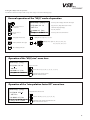
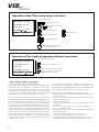
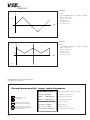
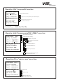
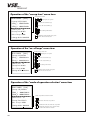
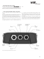
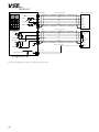
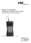
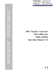
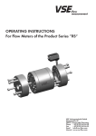
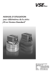
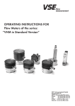
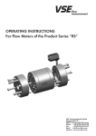
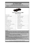
 Operating instructions
”pulse–generator TB2“ Testbox
Generator for generating A and B quadrature signals
VSE Volumentechnik GmbH
Hönnestraße 49
58809 Neuenrade/Germany
Phone + 49 (0)23 94/616 30
Fax + 49 (0)23 94/616 33
E-Mail [email protected]
Internet www.vse-flow.com
1
Contents
Page
Safety instructions. . . . . . . . . . . . . . . . . . . . . . . . . . . . . . . . . . . . . . . . . . . . . . . . . . . . . . . . . . . . . 3
General technical data . . . . . . . . . . . . . . . . . . . . . . . . . . . . . . . . . . . . . . . . . . . . . . . . . . . . . . . . 3
General information . . . . . . . . . . . . . . . . . . . . . . . . . . . . . . . . . . . . . . . . . . . . . . . . . . . . . . . . . . . 3
Description. . . . . . . . . . . . . . . . . . . . . . . . . . . . . . . . . . . . . . . . . . . . . . . . . . . . . . . . . . . . . . . . . . 4
The ”manual“ operating mode . . . . . . . . . . . . . . . . . . . . . . . . . . . . . . . . . . . . . . . . . . . . . . . . . . 4
1. Description of the ”manual“ operating mode . . . . . . . . . . . . . . . . . . . . . . . . . . . . . . . . . . 4
2. Using the ”manual“ mode of operation . . . . . . . . . . . . . . . . . . . . . . . . . . . . . . . . . . . . . . . 5
The ”VS(I)“ mode of operation . . . . . . . . . . . . . . . . . . . . . . . . . . . . . . . . . . . . . . . . . . . . . . . . . . 6
1. Description of the ”VS(I)“ mode of operation . . . . . . . . . . . . . . . . . . . . . . . . . . . . . . . . . . 6
2. Using the ”VS(I)“ mode of operation . . . . . . . . . . . . . . . . . . . . . . . . . . . . . . . . . . . . . . . . 7
The ”sweep“ mode of operation. . . . . . . . . . . . . . . . . . . . . . . . . . . . . . . . . . . . . . . . . . . . . . . . . 8
1. Description of the ”sweep“ mode of operation. . . . . . . . . . . . . . . . . . . . . . . . . . . . . . . . . 8
2. Functions of the ”sweep“ mode of operation. . . . . . . . . . . . . . . . . . . . . . . . . . . . . . . . . . . 9
3. Operating the ”sweep“ mode of operation. . . . . . . . . . . . . . . . . . . . . . . . . . . . . . . . . . . 10
Resetting to the works setting. . . . . . . . . . . . . . . . . . . . . . . . . . . . . . . . . . . . . . . . . . . . . . . . . . . 13
”pulse–generator TB2“ testbox connections. . . . . . . . . . . . . . . . . . . . . . . . . . . . . . . . . . . . . . . 13
Technical data . . . . . . . . . . . . . . . . . . . . . . . . . . . . . . . . . . . . . . . . . . . . . . . . . . . . . . . . . . . . . . 15
2
Safety instructions
Dear customer, dear user,
This description includes important instructions concerning the installation, function and the operation. This information is therefore
an important part of the device. A non-observance can result in damage being caused or the safety of personnel and plant being
impaired!
The device is only to be installed and commissioned by an electrical specialist.
If the device is to be used in processes by which a possible malfunction or incorrect operation can pose a risk to personnel and plant,
corresponding safety precautions are to be taken in order to avoid this.
The general standard for the construction of switch cabinets in the machine construction industry have validity for the installation.
This document is not managed by an updating service of VSE Volumentechnik GmbH.
Amendments can be made to this document without further notification; errors excepted.
• General technical data
•Simulates the output signals of incremental measuring systems (A, B with 90° phase shifting)
•Output frequency adjustable between 0 and 250 kHz
•Resolution of 0.1 Hz
•Frequency accuracy of 100 ppm
•Simulation of flow metering with VSE flow meters series VS(I) •Sweep function, which takes the direction of rotations of the most diverse frequency, ranges into account
•Reversible direction of rotation (phase position A/B)
•Adjustable frequency/flow divisions during operation
•Output A, B with HTL level 1–28 V; optional additional differential outputs A,/A; B,/B with HTL level 10–28 V or RS422 level •Large distribution voltage range 10–28 V DC
•Connection via a round M12 plug
• General information
It is not possible to imagine not using incremental measuring systems in almost
all industrial areas. This technology is wide-spread for flow metering in fluid
engineering and rotational speed counting in motion power engineering.
Additional applications are path measuring, position measuring and speed
measuring in industrial system solutions.
With the ”pulse – generator TB2“ testbox from VSE Volumentechnik GmbH,
incremental sensor signals or two 90° phase-shifted pulse signals A and B
are generated respectively. This pulse generator is able to generate frequencies of between 0.1Hz and 250,000.0Hz. The resolution is 0.1Hz. The incremental rotary encoder signals can either be adjusted by directly entering
the frequency or by using a special menu to specify flow meter values from
the VS(I) series of VSE flow meters. The construction size, interpolation factor
and the corresponding flow unit are taken into account, when generating the
flows. An additional menu can be used to run through stipulated frequency
ranges. Hereby, the direction of rotation is switched, depending on the set
frequency range, i.e. the phase position of both of the quadrature signals A
and B is shifted by 90° null.
The following tasks can be fulfilled with the assistance of the incremental
pulse encoder:
•Qualifying the usage possibilities of a measuring system for the desired
application
•Checking of the layout of an incremental measuring system
•Testing the functioning of machine components and control units or
evaluation units during the development phase
•Checking of setting parameters of electronic evaluation units or con verters without installing the mechanical components (e.g. flow sensors)
•Checking of cabling between the sensory technology and the electronic
measuring devices during commissioning
•Simulation of incremental sensor signals, when servicing plants
•Simulation of the flow quantities of VSE flow meters (VS(I) series)
•Checking of incremental measurement data recordings and their dynamics
•Testing the frequency behavior of switchings
•Simple error analysis in case of plant disturbances
It is a very useful and inexpensive means for the simulation of incremental
encoder signals.
3
• Description
The ”pulse–generator TB2“ testbox has three different types of operation
or modes:
The operation of the ”pulse–generator TB2“ testbox is quickly understandable and utilizes the simple keypad. 1.”manual“ mode: setting of a frequency between 0.0 Hz and
250,000.0 Hz
2.”VS(I)“ mode: setting of a measured flow value, stipulating the VS(I)
constructional size, the interpolation factor and the flow unit 3.”sweep“ mode: setting of linear sweep ranges between two frequency
values • The ”manual“ operating mode
1. Description of the “manual“ operating mode
The ”manual“ operating mode enables a direct entering of the user-related
frequency. The desired frequency can simply be entered using the numeric
keypad. The entered frequency will be stored after it has been acknowledged. The output of the incremental pulses is started and stopped using
the separate start/stop key . The direction of rotations can be changed,
i.e. the phase position of both of the quadrature signals can be shifted by
90° (see Fig. 1) using the ”direction“ key. An additional function is pro-
vided by the key,
with which the entered frequency can be directly split. If
%
only this key is activated, the frequency is output in the following percentages:
10%, 1%, 100%. In combination with a numeric key, it is possible to enter the
6
frequency in percentages of 10, e.g. pressing the keys and simulta%
neously results in 60% of the entered frequency being output. The
frequency display is updated accordingly.
n/Q
pos. direction of rotation
t
neg. direction of rotation
pos. direction of rotation (from A B)
neg. direction of rotation (from B
A)
Signal from channel 1
t
Signal from channel 2
t
Change in the
direction of rotation
n/Q = 0
Fig. 1: Change of direction of the quadrature signals
4
2. Using the ”manual“ mode of operation
The ”manual“ mode of operation is used as follows:
General operation of the "manual" mode of operation
Change between each of
the menu items
Enter
Entering the selected
menu item
Mode MANUAL [Start ]
Mode of operating display; Status of the frequency output
- 100% Frequency
Displays the current frequency output split
> FRQ +000120.1 Hz
Frequency entry menu item
> change Mode VS(I)
Mode of operation selection menu item
%
Changing the direction of rotation
Splitting the frequency output 10%, 1%, 100%
split
direction
Enable / Disable of frequency-output
start / stop
9
7
8
%
4
5
6
split
1
2
3
Splitting the frequency output
10%, 20%, 30%, 40%, 50%,
60%, 70%, 80%, 90%, 100%
0 (100%)
Operation of the "frequency entry" menu item
Frequency entry menu item
Mode MANUAL [Start ]
- 100% Frequency
x FRQ +000120.1 Hz
Changing the cursor position
+-
or
direction
> change Mode VS(I)
Changing the direction of rotation
in the entry
Increase the selected number (+1)
9
7
8
4
5
6
1
2
3
Direct entry of the numbers
0
Enter
Confirmation of the entered frequency value
Return to the menu item selection
Decrease the selected number (-1)
Operation of the "mode of operation selection" menu item
Mode of operation selection menu item
Mode MANUAL [Start ]
- 100% Frequency
Selection of the mode of operation
> FRQ +000120.1 Hz
x change Mode VS(I)
Enter
Confirmation of the selected mode of operation
Entering the selected mode of operation
or return to the menu item selection
5
• The ”VS(I)“ mode of operation
1. Description of the “VS(I)“ mode of operation
The ”VS(I)“ (VS(I)flow meter series) mode of operation was especially
developed for the ”VS(I)“ flow sensor system from VSE Volumentechnik
GmbH.
Flow meters made by VSE Volumentechnik GmbH measure the volume flow
of liquids according to the toothed wheel principle. A pair of very precisely
adjusted toothed wheels in the housing constitutes the meter. A signal pickup system registers the meter rotation free of contact and tooth by tooth.
Each tooth is output as a digital pulse. The gaps in the teeth of the meter
wheels form meter chambers in the areas in which they are completely
enclosed by the housing walls; these chambers digitalize liquid flow depending on their chamber volume. The liquid flow quantity within one meter rotation of a tooth division forms the volume measurement per pulse (Vm) and
is defined in cm³/pulse. It identifies the constructional size of a flow meter.
The two-channel, incremental output of the digital signals provides a higher
measured value resolution and a detection of the flow direction.
Fig. 2: VSE flow meters
An explicit simulation of the flow values of these flow meters is possible in
the ”VS(I)“ mode of operation.
Unit
The constructional sizes of the VS(I) are included in a menu item in a selectable tabular form. The corresponding interpolation factor can also be
selected, when using VSI flow meters. This is to be programmed with 1,
when using the standard VS version. The desired flow is directly entered
using the numeric keys. A corresponding flow unit is to be set prior to this. A
choice can be made from seven different units:
Liters per hour (l/h)
l/h
Liters per second (l/s)
l/s
Liters per minute (l/min)
Display
l/min
US gallons per minute (USgal/min)
GPM
US gallons per hour (USgal/h)
GPH
US gallons per second (USgal/s)
GPS
Frequency display (Hz)
Hz
Table 1: programmable units
The flow entry field is adapted in accordance with the selected construction
size and unit.
Unit
The unit can also be changed during operation by using the ”unit“ key.
The flow meter value display is changed automatically.
If the unit ”Hz“ should be selected, the corresponding output frequency is
displayed, taking the set frequency split parameter and the IPF factor into
account. Furthermore, in this mode it is also possible to have the flow meter
value or frequency respectively, displayed as a percentage of the entry, by
using the ”split“ key
or a corresponding key combination (e.g. and
%
%
6 ).
6
With these options, one is explicitly able to simulate flows in order to set
and optimize the evaluation and converter units correspondingly without
taking the fluid circulation into operation or having to make an installation.
The construction size VS(I), interpolation factor IPF, flow meter value Q and
the flow unit are stored after they have been entered in the device.
2. Using the ”VS(I)“ mode of operation
You will find a detailed description of the usage of the ”VS(I)“ menu on the following pages.
General operation of the "VS(I)" mode of operation
Mode VS(I)
Change between each of
the menu items
Enter
Entering the selected
menu item
Changing the flow direction
Mode of operation display; Status of the flow output
>VS(I) 0.02 >IPF 10
VS(I) size menu / interpolation factor IPF menu
- 90% Flow
Current flow output split display
>Q -00001.25 l/min
Flow entry menu item
>change Mode SWEEP
Mode of operation selection menu item
%
Splitting the flow output 10%, 1%, 100%
split
direction
Enable / Disable the flow output
start / stop
Unit
[ Stop ]
7
8
%
4
5
6
split
1
2
3
9
Splitting the flow output 10%, 20%, 30%, 40%, 50%,
60%, 70%, 80%, 90%, 100%
0 (100%)
Direct changing of the unit
unit
Operation of the "VS(I) size" menu item
Mode VS( I)
[Stop ]
x VS( I)0.02 >IPF 10
VS(I) size menu item
- 90% Flow
Selection of the size (0,02; 0,04; 0,1; 0,2; 0,4; 1; 2; 4; 10)
>Q -00001.25 l/min
>change Mode SWEEP
Enter
Confirmation of the selected VS(I) size
Return to the menu item selection
Operation of the "interpolation factor IPF" menu item
Mode VS( I)
[Stop ]
>VS( I)0.02 x IPF 10
Interpolation factor IPF menu item
- 90% Flow
Selection of the IPF (1, 2, 3, 4, 5, 8, 10, 12, 16)
>Q -00001.25 l/min
>change Mode SWEEP
Enter
Confirmation of the selected interpolation factor IPF
Return to the menu item selection
7
Operation of the "flow value entry" menu item
Flow value entry menu item
Mode VS(I)
[ Stop ]
Changing the cursor position
>VS(I) 0.02 >IPF 10
+-
- 90% Flow
Changing the direction of rotation
in the entry
or
direction
x Q -00001.25 l /min
Increase the selected number (+1)
>change Mode SWEEP
Selecting the flow unit
Decrease the selected number (-1)
7
8
4
5
6
1
2
3
9
Direct entering of the numbers
0
Enter
Confirmation of the entered frequency value
Return to the menu item selection
Operation of the "mode of operation selection" menu item
Mode VS( I)
[ Stop ]
Mode of operation selection menu item
>VS( I)0.02 >IPF 10
Selection of the mode of operation
- 90% Flow
>Q -00001.25 l/min
x changeMode S WEEP
Enter
Confirmation of the selected mode of operation
Entering the selected mode of operation menu
or return to the menu item selection
• The ”sweep“ mode of operation
1. Description of the “sweep“ mode of operation
The ”sweep“ operation enables the scan or sweep of a fixed range between
two frequency values. The start frequency, end frequency and the sweep
time are programmed. Different frequency directions can also be selected.
One function permits the starting of the sweep process with null or in a null
scan respectively. This enables the simulation of the most diverse incremental
frequency processes such as a flow characteristic for a servo valve.
The sweep characteristic is linear (ramp). It should, however, be taken into
account that the frequency is actually changed incrementally and not linear. It should also be taken into account how the device actually reacts if extreme sweep time and sweep range combinations are used. In sweep mode,
the software generates a table with 1200 intermediate frequencies, including the stipulated start and end frequencies. In the activated sweep mode,
each used frequency has to be extracted from the table and processed. The
frequency resolution of the steps depends on the programmed sweep range
and the sweep time or sweep rate respectively. A wide sweep range and a
fast sweep rate result in a very rough frequency resolution of the steps. Generally speaking, ”sweeping“ is normally used in context of a measuring data
recording or with an oscilloscope, in order to test the frequency behavior of
evaluation devices or circuits.
8
A separate trigger outlet ”TRIGOUT“ is available for the triggering of oscilloscopes. This trigger outlet changes to low level at the start of the sweep
and remains in this status during the first frequency step. The TRIGOUT status
returns to high level after the first frequency step has been completed.
The ”sweep“ mode of operation has the following technical data:
• Sweep simulations of incremental frequency responses with and without
changes of direction
• Sweep modes of operation: single sweep and continuous sweep opera-
tion due to adjustable loops
• Sweep characteristic: linear
• 4 different incremental sweep modes with two cutoff frequencies can be
programmed
• The start and end frequencies can be adjusted infinitely (0.1 …
250,000.0 Hz) within a range
• Triggering of an oscilloscope or x-y recorder possible due to an additional
trigger outlet TRIGOUT
• Sweep direction exchangeable via a mode change-over
• ”Sweep-Start“ can be adjusted at zero or at „start on zero“
• Sweep time can be infinitely variably adjusted between 0.1 s ... 20.0 s
• A programmable number of loops can be adjusted between 1 and 1000
2. Functions of the “sweep“ mode of operation
The following ”sweep“ functions of incremental signals are possible with the ”pulse–generator TB2“:
Example 1
Settings: f[Hz]
- Sweep UP (FRQ_1 ==> FRQ_2) - FRQ_1 +000000.0Hz
- FRQ_2 +002000.0Hz
pos. direction f[Hz]
- Start on zero off
- SweepTime 005.0s
- No. of loops 0002
f[Hz]
pos. direction
2000.0
f[Hz]
pos. direction
2000.0
0
5.0
t[s]
pos. direction
neg. direction
0
neg. direction
5.0
t[s]
f[Hz]
pos. direction
neg. direction
2000.0
neg. direction
f[Hz]
f[Hz]
pos. direction
2000.0
100.0
0
5.0
t[s]
0
5.0
t[s]
100.0
neg. direction
Example 2
loop 1
2000.0
Settings:
- Sweepf[Hz]
DOWN (FRQ_2 ==> FRQ_1) pos.-direction
FRQ_1 +000100.0Hz
loop 1
500.0
- FRQ_2 +002000.0Hz
2000.0
- Start on zero off
0
- SweepTime 005.0s
- No. of loops 0002
pos. direction
loop
loop 2
500.0
0
f[Hz]
neg. direction
neg. direction
pos. direction
f[Hz]
neg. direction
pos. direction
pos. direction
Example 3
Settings:
- Sweep UP (FRQ_1 ==> FRQ_2) - FRQ_1 +002000.0Hz
- FRQ_2 - 002000.0Hz
- Start on zero off
- SweepTime 005.0s
- No. of loops 0002
t[s]
f[Hz]
neg. direction
2000.0
t[s]
neg. direction
0
5.0
t[s]
2000.0
neg. direction
9
Example 4
Settings:
- Sweep UP / DOWN (FRQ_1 ==> FRQ_2 ==> FRQ_1) - FRQ_1 +02000.0Hz
- FRQ_2 - 02000.0Hz
- Start on zero on - SweepTime 005.0s
- No. of loops 0002
f[Hz]
pos. direction
f[Hz]
t[s]
pos. direction
neg. direction
t[s]
t[s]
neg. direction
f[Hz]
pos. direction
loop 1
loop 2
2000.0
t[s]
500.0
10.0
0
t[s]
Example 5
Settings:
- Sweep DOWN / UP (FRQ_2 ==> FRQ_1 ==> FRQ_2) - FRQ_1 +0500.0Hz
- FRQ_2 +02000.0Hz
- Start on zero off
- SweepTime 005.0s
- No. of loops 0002
neg. direction
t[s]
3. Operating the “sweep“ mode of operation
Adjusting the sweep parameters:
General operation of the "sweep" mode of operation
Mode SWEEP
Change between each of
the menu items
Enter
Entering the selected menu item
(only possible if sweep is disabled!)
Enable / Disable the sweep output
(Activiation only possible outside of the
start / stop menu items possible!)
10
[ Start ]
Mode of operation display; Status of the sweep output
>Sweep UP/DOWN
>FRQ_1 –000250.0Hz
Sweep functions selection menu item
>FRQ_2 +000250.0Hz
Frequency entry FRQ_2 menu item
>Start on zero off
Start on zero menu item
>Sweep T ime 000.5s
Time entry menu item
>No. of loops 1000
Number of loops menu item
>change Mode MANUAL
Mode of operation selection menu item
Frequency entry FRQ_1 menu item
Operation of the "sweep mode" menu item
Mode SWEEP
[Start ]
x Sweep UP/DOWN
Sweep functions selection menu item
>FRQ_1 –000250.0 Hz
>FRQ_2 +000250.0 Hz
Selecting the sweep mode (UP; DOWN; UP/DOWN; DOWN/UP)
>Start on zero off
>Sweep T ime 000.5s
Enter
>No. of loops 1000
Confirmation of the selected sweep mode
Return to the menu item selection
>change Mode MANUAL
UP/DOWN : FRQ_1 >> FRQ_2 >> FRQ_1
DOWN/UP : FRQ_2 >> FRQ_1 >> FRQ_2
UP : FRQ_1 >> FRQ_2
DOWN : FRQ_2 >> FRQ_1
Operation of the "frequency entry FRQ_1; FRQ_2" menu item
Frequency entry menu item FRQ_1
Mode SWEEP
[Start ]
Frequency entry menu item FRQ_2
>Sweep UP /DOWN
x FRQ_1 –000250.0 Hz
Changing the cursor position
+-
x FRQ_2 +000250.0 Hz
Changing the direction of rotation
in the entry
or
direction
>Start on zero off
Increase the selected number (+1)
>Sweep T ime 000.5s
Decrease the selected number (-1)
>No. of loops 1000
>change Mode MANUAL
9
7
8
4
5
6
1
2
3
Direct entering of the numbers
0
Enter
Confirmation of the entered frequency value
Return to the menu item selection
Operation of the "start on zero" menu item
Mode SWEEP
[Start ]
>Sweep UP /DOWN
>FRQ_1 –000250.0Hz
>FRQ_2 +000250.0 Hz
x Start on zero off
Start on zero menu item
>Sweep T ime 000.5s
Selection (on; off)
>No. of loops 1000
>change Mode MANUAL
Enter
Confirmation of the selection
Return to the menu item selection
11
Operation of the "sweep time" menu item
Sweep time menu item
Mode SWEEP
[Start ]
Changing the cursor position
>Sweep UP /D OWN
>FRQ_1 –000250.0 Hz
Increase the selected number (+1)
>FRQ_2 +000250.0 Hz
Decrease the selected number (-1)
>Start on zero off
x Sweep T ime 010.5s
9
7
8
4
5
6
1
2
3
0
>No. of loops 1000
>change Mode MANUAL
Direct entering of the numbers
Confirmation of the entered frequency value
Return to the menu item selection
Enter
Operation of the "no. of loops" menu item
Number of loops menu item
Mode SWEEP
[Start ]
Changing the cursor position
>Sweep UP /DOWN
>FRQ_1 –000250.0 Hz
Increase the selected number (+1)
>FRQ_2 +000250.0 Hz
>Start on zero off
>Sweep T ime 010.5s
x No. of loops 0100
>change Mode MANUAL
Decrease the selected number (-1)
7
8
4
5
6
1
2
3
9
Direct entering of the numbers
0
Enter
Confirmation of the entered frequency value
Return to the menu item selection
Operation of the "mode of operation selection" menu item
Mode SWEEP
[Start ]
>Sweep UP /DOWN
>FRQ_1 –000250.0 Hz
>FRQ_2 +000250.0 Hz
Mode of operation selection menu item
>Start on zero off
>Sweep T ime 010.5 s
Selection of the mode of operation
>No. of loops 0100
x change Mode MANUAL
12
Enter
Confirmation of the selected mode of operation
Entering the selected mode of operation menu
or return to the menu item selection
• Resetting to the works setting
Unit
The testbox can be reset by pressing the keys simultan-
eously. This key combination initiates the reset process. The power failuresafe memory is hereby reloaded with ”default“ values before being reset.
After the reset, the ”pulse–generator TB2“ is in the ”manual“ mode of ope-
ration.
• “pulse–generator TB2“ testbox connections
The ”pulse–generator TB2“ testbox has a M12 plug and a BMC-socket as
standard.
The device is provided with power and outputs the incremental pulse
signals via the M12 plug. A connection diagram is shown in Fig. 4.
The ”TRIGOUT“ trigger outlet for the sweep operation is at the BNC-socket.
Special versions are equipped with an additional M12 plug on the device.
This is situated between the standard M12 plug and the BNC-socket (see
Fig. 3).
At this plug, the digital signals can be differentially output at this plug with
the supply voltage (HTL level: 10–28 V) or in a RS422 format (level 2–3 V,
fmax = 150 kHZ) as requested. Each signal is hereby transmitted to 2 lines
with complementary levels. The logic level is determined at the receiver
on the basis of the difference between the two lines A, B and /A, /B. This
makes long transmission links possible in addition to increasing the interference immunity.
The connection cable should only be a well-screened cable with a wire
cross-section of ≥ 4 x 0.25 mm². Please note that the round M12 plug has a
metallic housing, a connection for the shielding and that the potential of the
grounding conductor PE or the ground is connected to the cable screen.
Fig. 3: The ”pulse–generator TB2“ testbox connections
13
M12-standard
Mode MANUAL [Start]
-100% Frequency
x FRQ +000 120.1 Hz
> change Mode SWEEP
brown
+U b
white
Channel 1
%
7
8
9
4
5
6
1
2
3
+-
0
Enter
VSE connecting cable
blue
-Ub (GND)
black
Channel 2
Evaluation unit (e.g. display)
+10-28V DC
signalinput 1
GND
signalinput 2
PE/GND
Unit
M12-special
VSE connecting cable
Evaluation unit (e.g. PLC)
brown
Channel A
white
diff. signalinput A
blue
Channel /A
black
Channel B
diff. signalinput B
PE/GND
BNC–coaxial cable
Channel /B
BNC–socket
TRIGOUT (low-active)
pulse-generator TB2
Fig. 4: Connecting diagram for the power supply and the signal outputs
14
Triggerinput
• Technical data
Power supply
Supply voltage
U = 10 … 28 V DC; voltage reversal-safe
Current consumption
I0 = 42 mA (at 24 V DC); unloaded
Signal outputs (standard)
Signal voltage output
(channel 1; channel 2)
USS = 9 … 27 V DC
Signal output current
IOUT = 300 mA max at 24 V DC (channel 1; channel 2)
Output preamps
Push-Pull preamps; current limited; short-circuit proof; internal cable adaptation;
low saturation voltage; temperature protection circuit with hysteresis;
high-impedance outlets in case of failures
Additional signal outputs (special):
Signal output
Channel A, /A (with inversion),
Channel B, /B (with inversion)
Signal output level
HTL level 10 – 30 V or RS422 level
Signal voltage output
USS = 8 … 27 V DC differential (with HTL)
USS = 0,4 … 3,2 V DC differential (with RS422)
Signal output current
IOUT = 200 mA (with HTL),
IOUT = 20 mA (with RS422)
Output preamps
Push-Pull preamps; current limited; short-circuit proof;
internal cable adaptation (with HTL) or
RS422-driver AM26C31 (fmax = 150 kHz)
Housing
Dimensions
L x W x H 209,3 x 98 x 34,8 mm
Material
ABS (acrylonitrile-butadiene-styrene)
Color
graphite gray
System of protection
IP64
15
16
02/10 www.plakart.de
VSE Volumentechnik GmbH
Hönnestraße 49
58809 Neuenrade/Germany
Phone + 49 (0)23 94 /616 30
Fax + 49 (0)23 94 /616 33
E-Mail [email protected]
Internet www.vse-flow.com