1
developing
solutions
Operating Instructions
DE58
Digital Differential Pressure Transmitter / Switch
with 3½ digit LED display
Table of Contents
1
2
3
4
5
6
7
8
9
10
11
12
13
14
Safety instructions
Intended applications
Product description and functions
Installation
Inbetriebnahme
Maintenance
Transport
Service
Accessories
Disposal
Technical specifications
Dimensioned drawings
Ordering Code
Declaration of Conformity
1
Safety instructions
1.1
General information
This operating manual contains detailed
information about the installation, operation and maintenance of the instrument.
This information must be observed and
read by the installer, operator and other skilled personnel prior to any installation and commissioning
of the instrument.
The following chapters, especially the instructions
on installation, commissioning and maintenance
contain important safety information, the noncompliance of which may result in hazards to persons, animals, environment and objects.
*09005272*
*09005272* BA_EN_DE58 Rev.D 06/15
This operating manual forms part of the product and
must be kept in the immediate vicinity of the instrument for easy access by the responsible personnel
at any time.
1.1
Personnel qualification
Only personnel trained in the installation, commissioning and operation of this product may install
and operate the same.
Skilled personnel are persons who are able to judge
delegated work and possible hazards based on
their technical education, proficiency and experiences, particularly due to their knowledge about the
applicable norms.
1.2
Risks of non-compliance with safety
instructions
Non-compliance with these safety instructions, inappropriate use of this product, and/or operation of
this product outside the limits specified for any of its
technical parameters, may result in harm to persons, the environment or the system in which it is
installed.
The producer is not liable for any claims for damages in such circumstances.
1.3
Safety instructions for operators
Safety instructions for the proper use of this product
must be followed. This information must be available at all times to personnel responsible for installation, operation, maintenance and inspection of this
product.
Adequate steps must be taken to prevent the occurrence of hazardous conditions that can be caused
by electric energy and the convertible energy of the
process media and/or improper connection of the
instrument. Detailed information can be found in the
relevant national and/or international
rules and regulations.
In Germany DIN EN, UVV apply, for industryspecific applications regulations of DVGW, Ex, GL,
as well as the rules of the local authorities (EVUs in
Germany).
1.4
3
Product description and functions
3.1
Functional scheme
3.2
Principles of operation
Forbidden modifications
Modification or other technical alteration of the device by the customer is not permissible. This also
applies for the use of spare parts. Any eventual
modifications/ variations will be carried out solely by
Fischer Mess- und Regeltechnik GmbH.
1.5
Impermissible operational modes
The operational dependability of the device is guaranteed only if it is used as intended. The device
version must be adapted to the medium used in the
system. The limiting values stated in the technical
data must not be exceeded.
1.6
Safety Considerations during Installation and Maintenance
The safety instructions stated in this manual, existing national regulations on accident prevention and
the internal rules and procedures on working, operation and safety of the operator are to be observed.
It is the responsibility of the operator to ensure that
only authorised and skilled technical personnel carry out any required maintenance, inspection and installation works.
1.7
Explanation of symbols
WARNING!
...indicates a possible hazardous situation the non-observance of which
might result in hazards to humans, animals, environment and objects.
INFORMATION!
…points out important information for
efficient and trouble-free operation.
TIP!
…points out useful recommendations
that are not necessarily required for
operation that might however be of
use in certain situations.
2
Intended applications
The product includes the functions of sensing, signal conversion, display, signal transmission, and
limit detection of differential pressure of gases and
liquids. The product must be used only for applications and under conditions specified by the manufacturer. In case of uncertainties, the user should
consult the manufacturer before installing and using
the product.
The instrument uses a tough, flexible sensing diaphragm embedded between stiffening plates and
balanced by springs on either side. The diaphragm
is at zero position when pressures on either side of
the diaphragm are equal. Inequality of pressures
results in deflecting the diaphragm towards the lower pressure side until a new equilibrium determined
by the changed balance of forces is reached. Fastened to the center of the diaphragm is an axial rod,
the other end of which forms the moving core of a
linear inductive displacement transducer. The linear
displacement is proportional to the pressure difference across the diaphragm. This displacement is
converted by the transmitter's electronic module to
a standard electrical signal output. An optional output signal can be slew rate limited, spreaded, inverted and piecewise transformed nonlinearly by
means of a table function.
4
Installation
The device is equipped with a wall-mounting adaptor plate.
The pressure transmitters are calibrated at the factory while mounted vertically, pressure ports downward. However, they can be mounted in any orientation. If they are installed with any orientation other
than vertical (pressure ports downward) the zero
point must be reset.
IP65 protection for the housing is guaranteed only if
suitable connecting cable is used.
If the instrument is intended for outdoor application,
we highly recommend using an adequate protective
housing (or at least a big enough shelter) as permanent protection against UV-radiation on the
membrane keyboard and against exposure of the
instrument to rain or snow.
4.2.1
Ensure that process equipment and pressure
lines are at atmospheric pressure before making pressure connections.
Pressure lines must be kept as short as possible
and must not have short bends to avoid measurement errors induced by pressure line delays.
If the pressure transmitter is subjected to pressure
when it is started up, zero point checking and adjustment is not possible. In such cases, only electrical connections of the instrument should be made,
but not the pressure connections.
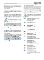
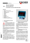
4.2
SP1no
Pressure lines must have a downward gradient
throughout from the pressure instrument to the process vessel / pipe. This is to prevent formation of air
/ gas pockets (for liquid applications) and liquid
plugs (for air / gas applications). If this continuous
downward gradient cannot be provided for any reason, then suitable water and / or air separation devices must be inserted into the pressure lines.
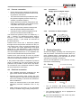
BN
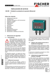
The instruments pressure ports are marked by "+"
and "-" symbols. For differential pressure applications the "+" port must be connected to the higher
pressure and the "-" port should be connected to
the lower pressure.
5
GN/YE
BK
FE
Signal +Sig
BK
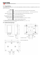
Connector 2: Switch outputs
SP1com
4.2.2
BU
Carefully check the pressure-tightness of all
pressure connections before start-up.
Supply -Ub
•
BU
Ensure that process pressure is always less
than the specified safe pressure rating.
SP2com
•
WH
Ensure that the mechanical configuration and
materials of construction of the instrument are
compatible with the process media.
Signal -Sig
•
WH
The instrument should be provided with suitable protection against pressure surges (e.g.,
snubber or pulsation damper).
Internal connection
SP2no
•
Connector 1:
Supply input and Signal output
BN
•
Process connection
Supply +Ub
4.1
Starting Operation
All electrical supply, operating and measuring lines
and the pressure connections must have been correctly installed before commissioning. All supply
lines shall be arranged such that there are no mechanical forces acting on the device.
Check the leak-tightness of the pressure connections before commissioning.
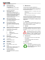
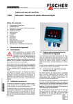
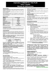
5.1
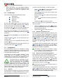
Display
3½ Character LED Display
Switching Output 2
Switching Output1
Electrical connection
•
Only qualified technicians authorized for this
type of work should undertake installation.
•
Electrical connections must comply with relevant international, national and local regulations
and norms relating to electrical and instrumentation installations.
•
Switch off electrical power to the plant before
attempting electrical installation work of any
kind.
•
Make electrical connections to the transmitter
through a suitable energy-limiting safety device
Control keys
Measuring
unit
•
The 3½ character LED display presents the
current differential pressure in normal operating
mode.
•
The selected measuring unit is highlighted at
the right of the display.
The units represented on the screen may deviate from the actual design.
•
Above the display, two LEDs symbolise
the condition of the switching outputs. As soon
as the switch is closed, the applicable LED
lights up.
5.2
Control keys
The control keys have the following functions:
ÿ
û
þ
Menu down
Decrease value
Enter key
Menu up
Increase value
By using the middle û key on the membrane keypad you can access the parameter menu (settings
mode). The display now shows the text ESc.
By using the right þ key you can move up within the
menu and can now select numerous parameters.
By pressing the left ÿ key, you can move downwards in the menu and finally get back to the ESC
parameter.
By pressing the middle û key you can call up a parameter.
Using the ÿ and þ keys, you can then set the parameter value.
In order to take on the adjusted parameter value,
press the û key.
All adjusted parameters are first then saved if you
leave the menu via the ESC parameter.
5.3
Configuration
For commissioning there is a multitude of setting
options for optimum adaptation of the device to the
measuring point and task at hand. This section covers these options step by step.
In order to set a parameter, proceed as follows:
•
Press the Enter û key in order to switch into the
menu. ESc will appear on the display.
•
Use the ÿ þ arrow keys in order to select a parameter from the list.
•
Press the Enter û key in order to call up the parameters.
•
Use the ÿ þ arrow keys to set the required value.
•
Use the Enter û key to save the value.
After you have set all the parameters, leave the
2
menu as follows:
•
Using the ÿ þ arrow keys, set the ESc parameter. You can find this both at the start and at the
end of the parameter list.
•
Use the Enter û key to leave the menu.
5.3.2
Selection of pressure unit
First select the required pressure measuring unit.
The unit currently valid is highlighted on the right
next to the figure display. For setting, use the middle û key and then look using the right þ key for
the ON parameter. Press û again and then change
the value shown using þ or ÿ. After selection, save
the value with û and ON will appear again in the
display.
To complete, leave the settings mode. Press ÿ until
ESc and then û. Now the pressure currently measured is represented. On the right of this, the correct
pressure unit should be highlighted.
The display circumference is limited to ±1999.
For this reason not all specified pressure units
may in individual cases be selectable.
5.3.3
Zero point control and adjustment
1
Depending on the device design available, some
menu points are not available. For example, all
characteristic curve functions are masked from the
menu if the device does not have a signal output.
The device can be completely set conveniently on the PC using a PC adaptor.
There all parameters are immediately
visible and accessible. In addition, the
complete configuration can be loaded, saved and
documented as a control print-out. Further guidelines on this program can be found in the documentation for this program (see accessories).
5.3.1
General
Put the device electrically into operation and ensure
that the device is initially depressurised (if necessary, disconnect the pressure connection lines).
1
With reference to the transmitter signal, voltage output, current
output etc.
Ensure that the device is depressurised (if necessary, disconnect the pressure connection lines).
If the device does not indicate precisely zero,
please note the shown value. The OF1 parameter
enables you to adjust the offset exactly to zero. To
do this, you must enter the noted value with the
sign reversed, and save it under OF1.
The entered value is purely a number value; no
decimal point is shown
If the device has already been used, values for the
OF1 and nP parameters may have been entered. In
this case please set both parameter values to zero
and carry out the zero point alignment again.
Only when you leave the menu via the ESC parameter are the
set parameters valid.
2
After zero-point adjustment, the pressure sensing
lines can be reconnected.
The allocated signal values for MA and ME cannot be
changed (see type label, e.g. 0...10 V or 4...20 mA).
5.3.4
If MA ME, we speak of a rising characteristic curve.
The output signal increases as the pressure rises.
Damping and zero-point stabilizing
If there are unsteady pressure readings at this point
of time or during operation, you can use parameters
DAM and NP to stabilise the reading (and the output
signal).
The DAM parameter acts like a capillary throttle.
However, it only has an effect on the display, the
output signal and the switch points but not on the
measuring cell itself. You can set the response time
to pressure jumps using this parameter. The values
range comprehends 0.0 to 100.0 seconds.
With maximum damping, it will take
more than 2 minutes for the reading also to reach zero after a pressure jump
from nominal pressure (100 %) to zero.
In many cases, unsteady readings are not a problem during normal operating mode, but this is not
true for the idle state, i.e. if zero (differential) pressure is expected.
In such situations, parameter NP can be applied. Its
value defines a measuring value range of around
zero. The measuring value is set to zero within this
range.
Example:
3
For NP, a value of 0.08 mbar is entered. In this
case all pressures which lie within a range of 0.08 mbar to +0.08 mbar become zero. Only if
the pressure exceeds these limits, will the reading no longer indicate zero. The pressure value
and the reading do not however accord one
hundred percent with each other. Only after a
doubled value, i.e. from 0.16 mbar, will the
measuring pressure and the reading match
again.
5.3.5
Setting the output signal
The transmitter output signal primarily depends on
the measured pressure. However, you have the option to adjust the output signal to a large extent to
suit your requirements.
However, the basic measuring range
(indicated on the type label) and the
type of output signal (voltage or current)
are not variable.
The parameters MA (Start of measuring range) and
ME (End of measuring range) define the limits to
which the output signal can change at all. Both values are adjustable across the entire basic measuring range. The set values always refer to pressures
in the relevant valid pressure unit and are converted
when the unit is changed.
3
0.08 mbar ≙ 8 Pa
If MA > ME, we speak of a falling characteristic curve
and the output signal decreases as the pressure
rises.
The difference between values MA and ME must be at
least 25 % of the basic measuring range. The software will not allow larger spreads. You will not be
able to exit the menu if you have entered incorrect
range values.
Example:
With a basic measuring range of 400 Pa, the
following must apply: MA – ME 100 Pa.
5.3.6
Output signal limits (Namur)
The three parameters oG1, oG2 and oEr determine
independent of the pressure, the limit values for
output currents or voltages which must not be underrun or exceeded.
These limit values are superordinate to
the range determined through MA and ME.
They serve mainly to suppress error
messages in downstream systems
through short-term measuring range exceedances.
With the oG1 parameter, the limit value for the minimum output signal is determined. The output signal
cannot underrun this value. Generally this parameter is only expedient for devices with an output signal of 4...20 mA, because on these devices a value
below 3.8 mA is often evaluated as an error signal.
With the OG2 parameter, the limit value for the maximum output signal is determined. The output signal
cannot exceed this value. This parameter can be
used for all outputs (voltage and current) in order to
limit the maximum value to e.g. 10.2 V.
With the oer parameter, the value for the error signal is determined. The value specified with oEr is
emitted as an output signal if the device detects an
internal error and can no longer works correctly.
However, not all possible errors and defects can be
detected by the device.
If you set oG1 = OG2 = 0, the output signal is no longer checked for limits.
If you set oG1 to the maximum value (11
V or 21 mA), you can change using OG2
the output signal independent of pressure from zero to the maximum value. It
is not necessary to leave the menu item; the output
is then carried out immediately. You then operate
the device as a signal transmitter and can then
easily check the other signal processing.
5.3.7
Characteristic curve function F
For certain applications, a pressure measurement is
only an indirect measurement for the actual variable. Flow measurement across an aperture or filling
level determination through hydrostatic pressure
measurement is two typical examples of this. In
these cases it may be necessary to change the
output signal of the transmitter through a non-linear
characteristic curve so that the subsequent evaluation receives a signal linearly proportional to the actual measured value (e.g. volume in m³ or volume
flow in cm³/s etc.)
The F parameter allows you to select between the
following variants:
F
0
1
2
3...30
Linear characteristic curve (standard)
Root-extracted characteristic curve
Horizontal cylindrical tank
Support
point
table
with 3 to 30 value pairs
Whenever you change the value of F, the program
will create a new table. All previous table values are
rejected and replaced with new linear entries.
The tables for types F = 0 to F = 2 are not visible.
Here internal values are used for table calculation.
These values cannot be modified.
For F = 3...30, you only have influence on the 1...28
intermediate values (see 5.3.8) you only have access to the start and end value via the MA and ME parameters.
If the parameters MA and ME are changed,
the table will be deleted and F = 0 is set.
At the start of measuring range (MA), 0%
is emitted by the output signal (e.g. 0 mA).
At the end of measuring range (ME), 100% is emitted
by the output signal (e.g. 20 mA).
5.3.8
Menu jump LIN
If the value of F is larger than or the same as 3,
there is a submenu LIn. Here you can access all table values except for the start of the table (MA) and
the end (ME).
This submenu has its own entry and exit point,
which is represented with End. The table is not
saved until you switch back to this point in the main
menu, meaning that you switch back using the û
key to the LIN parameter.
If the table is not structured correctly, an error message Err will appear at this point, and you will not
be able to exit the submenu.
The table consists of 2...29 value pairs. On a device
4
with a power output, the first value pair is {I02|P02} .
The initial value I02 determines the level of the output signal. The second value P02 determines at
which pressure the output signal should be emitted.
Then come the value pairs {I03|P03} ... {I29|P29}.
The entry of or changes to the table values via the
membrane keyboard is extremely strenuous and
prone to errors. It is only intended as an emergency
solution in case access to the PC adaptor is not
possible.
The table is correct if the following applies for all
signal values: the value is larger than the previous
value. For the pressure values, therefore, either the
larger (rising characteristic curve) or the lower (falling characteristic curve) apply accordingly. A transition from a rising to a falling characteristic curve or
vice versa is not permitted.
5.3.9
Switch points
The two switching outputs are configured
through four parameters each.
The function of the switching output is determined through the parameters R1A, R1E, R1D and R1F.
The function of the switching output is determined through the parameters R2A, R2E, R2D and R2F.
R1A determines the switch-off point, and R1E determines the switch-on point for switching output 1.
The values are set in the valid measuring unit
(shown on the right).
Together, both the R1A and R1E parameters determine the switching function of switching output 1:
If R1A is smaller than R1E, the output switches on if
the measuring value exceeds R1E. It does not switch
off until the measuring value underruns R1A (hysteresis function).
If R1A and R1E are equal, the output switches on if the
measuring value exceeds R1E and off if the measuring value underruns R1A.
If R1A is larger than R1E, the output switches on if R1E
< measuring value < R1A applies (window function).
Both parameters can be set independently across
the entire measuring range.
If the measuring unit is switched, the switch points
are recalculated accordingly. Here rounding errors
may cause deviations in the last point.
R1D allows the reaction of the switching output 1 to
be delayed by 0.0 to 100.0 s. This value applies
equally for switch-on and switch-off.
4
With a voltage output {u02|P02} ... {u29|P29}.
R1F reverses the function of the switching output. If
the value = 1, the switching output functions as an
NO contact, if the value = 2, the switching output
functions as an NC contact.
5.3.10 Password
The last menu item -P- serves for the input of a
password. A value of 001 to 999 can be selected as
a password. The value 000 renders the password
function invalid.
If a password was assigned, a text PAS is shown after ESc and û, and you must enter the right value by
using û and þ ÿ. Only by doing so will you be able
to access all other menu items. In the event of an
error, the reading goes back to the start of the
menu ESc.
If the password is forgotten, it can only
be reset by the manufacturer or overwritten via the PC adapter.
5.3.11 Display options
The D0 parameter permits the reading to be steadied if the measuring value fluctuates severely. This
filter function is similar to the dAM function, but has
an effect only on the display and not on the output
signal. With D0 = -1, only the switch point LEDs can
be controlled. With D0 = -2, these are switched off.
5.4
After switching on the device, it will briefly indicate
the software version number and then enters the
normal operating mode. By using the middle û key
on the membrane keypad you can access the parameter menu. The reading now shows the text ESc.
By using the right þ key, you can choose the parameters from the following list one by one:
Note:
Depending on the device design, individual parameters may not be available
if the device does not possess this feature.
PAS
DAM
Enter password
(only comes up if password is active),
values range 000..999
000 = deactivated
Damping
(Jump response time T90),
values range 0.0...100.0s
d0
5.3.12 Reset to default values
The res function serves to reset all settings to default. Default values can only be defined via PC interface.
R1A
5.3.13 Free unit
R1E
If the device is designed for a "free" third unit
(membrane symbol: ), the display can be scaled
at will using the parameters MAF, MEF and dPF.
R1D
The measuring range defined through the parameters MA and ME is converted into MAF and MEF. Here
the table function ( F ) is also taken into account.
The value of dPF determines the position of a decimal point.
Parameter overview
R1F
R2A
R2E
R2D
Display damping
Value range -2...0...100.
-2 = Display off, LED switching pt. off
-1 = Display off, LED switching pt. on
0 = Display on, LED switching pt. on
1...100 Display damping
Switch-off point
From switching output
Switch-on point
From switching output
Switching delay
From switching output
Values range 0.0 to 100.0s.
This value applies equally for switch-on
and switch-off.
Switching function
From switching output
Values range 1,2
1 = Switching output as NO contact,
2 = Switching output as NC contact
Switch-off point
From switching output
Switch-on point
From switching output
Switching delay
From switching output
Values range 0.0 to 100.0s.
This value applies equally for switching
on or off.
R2F
Switching function
From switching output
Values range 1,2
1 = Switching output as NO contact,
2 = Switching output as NC contact
ON
MA
ME
ofi
F
Measuring range unit
Values range 1, 2, 3
The selection is highlighted on the
right-hand side next to the display. Not
all basic measuring ranges allow any
switching. The respective unit size can
only then be selected if the basic
measuring range of the device can be
represented meaningfully
Start of measuring range
The measuring value is set that result
in a minimum output signal.
(e.g.: 0V, 0mA or 4mA).
oG1
OG2
OEr
res
-P-
Maintenance
The device does not require maintenance.
In order to ensure reliable operation and a long service life of the device we recommend regular checking of the device as follows:
•
Check the function in connection with slave
components.
•
Check the tightness of the pressure connection
lines.
•
Check the electrical connections.
The exact test cycles have to be adapted to the operating and environmental conditions. The operating manuals of all other devices are also to be observed if there is an interaction of different device
components.
7
Transport
End of measuring range
The measuring value is set in a way
that results in a maximum output signal.
(e.g.: 10 V or 20 mA).
The product must be protected against severe impacts. Therefore transport is to be effected only in
the packaging intended for transport.
Offset correction measuring input 1
Value range -⅓ FS...0... +⅓ FS
All defective or faulty devices are to be sent directly
to our repair department. We would like to ask you
to coordinate all device returns with our sales department.
Characteristic curve function
Value range 0...30
0
1
2
3..30
lIn
6
= linear,
= root-extracted,
= horizontal cylindrical tank
= table
Menu entry
Submenu table processing
If F < 3, this menu item is masked.
Limit value
Minimum output signal
Limit value
Maximum output signal
Error signal
(Output signal in case of error)
Reset
All parameters to default values (specification of default values via PC)
Password settings
Value range 000 to 999
The value 000 means no password
protection.
8
Service
Remaining medium in and on dismantled measuring instruments may cause
danger to persons, environment and
equipment. Take reasonable precautions! Clean the instrument thoroughly if necessary.
9
Accessories
•
M12 connectors with pre-wired cable lengths
(on request)
•
PC serial interface adaptor with software:
model EU03.F300
10 Disposal
Protect your environment....
Kindly help us protecting the environment and dispose of or recycle the
used products in accordance with the
relevant regulations.
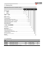
Technical specifications
Measuring range
Max. static operating pressure
mbar
0-160
0-250
bar
16 bar
Straight line error (max.)°
%FS
2.5 %
Straight line error (typ.)°
%FS
0.8 %
TC span (max.)°° %FS/10K
0.8 %
TC span (typ.)°° %FS/10K
0.2 %
TC zero point (max.)°° %FS/10K
0.8 %
TC zero point (typ.)°° %FS/10K
0.2 %
0-400
0-600
0.4 %
0.5 %
° : Straight line error = nonlinearity + hysteresis; at 25°C; pressure within specified range (characteristic linear, not spreaded)
°° : Pressure within specified range (characteristic linear, not spreaded); compensated temperature range 0 to 60°C
Operating temp. (ambient)
Operating temp. (media)
Storage temperature
Static operating pressure
Overload capacity
Protection class (housing)
-20 … 70°C
-20 … 70°C
-30 … 70°C
(see table)
single sided overpressure proof up to the rating of the measuring system;
(+) and (-) side, vacuum proof
IP 65 per DIN EN 60529
Electrical
Nominal supply voltage
Operating supply voltage
Output signal
Output signal load
Power consumption
Switching contacts
Display
24 V DC/AC
12 … 32 V DC/AC
0 … 20 mA, 4 … 20 mA, 0 … 10 V (3-wire)
For output current RL (UB - 4 V) / 0.02 A (UB 26V), else RL 1100
For output voltage RL 2 K (UB 15 V), RL 10 K (UB = 12 …15V)
Approx. 2 W/VA
2 sets of programmable voltage free relay contacts: NO or NC
Umax = 32 V DC/AC, Imax = 2 A, Pmax = 64 W/VA
Optional, instead of relay outputs:
2 programmable voltage free MOSFET switch outputs; NO/NC
U = 3 … 32 V DC/AC, Imax = 0.25 A, Pmax = 8 W/VA, RON 4
3½ digit LED
Connections
Electrical connections
Two round-shell multi-pin connector sockets (M12, male)
Connector 1: 5-pin: power input and analog signal output
Connector 2: 4-pin: relay contacts / solid-state switch outputs
Pressure connections
G 1/4 female threads with optional cutting ring fittings for 6 or 8 mm tube
Materials, Mounting
Materials, housing
Materials, media contact
Mounting
Polyamide PA 6.6
Brass, VITON®, EPDM
Wall mountable using adaptor plate
11 Programming
Via membrane key-switches or by using PC-programming interface (accessory), programming mode can be
password protected.
Settings:
Input filtering
Switch output
Measurement unit selection
Zero suppression
Output signal start / end value
Zero pressure calibration
Output characteristic
Password range
(1)
(2)
(3)
0.0 ... 100.0 secs (10 / 90% step response time) for signal output, display separated
activation point, de-activation point, response time delay (0.0 ... 100.0 secs), logic (N/O or N/C)
mbar / Pa / „free unit“ start value, end value and decimal place for „free unit“
0 ... 1/3 of main measurement range (1)
can be set at any point of measuring range (2)
± 1/3 of main measurement range (3)
Linear, square rooted, horizontal cylindr. tank, table (3...30 entries)
001 ... 999 (000 = password protection disabled)
Measured value deviations symmetric about zero, are set to zero. Used for zero drift suppression.
Maximum effective turn-down ratio = 4:1. Only the output signal is affected. Transfer function is inverted if start value > end value.
Zero calibration setting may change with mounting orientation.
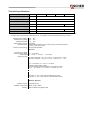
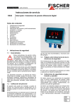
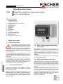
12 Dimensioned drawings
M12 connectors
Threaded hose clamp
Wall mounting adaptor plate
13 Ordering Code
Digital Differential Pressure Transmitter / Switch
Type DE58
Measuring range
0 … 160mbar ................................................................................ >
0 … 250mbar ................................................................................ >
0 … 400mbar ................................................................................ >
0 … 600mbar ................................................................................ >
M
6
8
8
C
K 0
M W
0
2
3
1
Diaphragm, Gaskets
EPDM
/ FKM ........................................................................................ > A
Pressure Chamber
Brass ...................................................................................................................... > M
Pressure connections
G 1/4 female thread...................................................................................................... >
Connector with male thread G1/4 B Brass .................................................................... >
Cutting ring connection of 1.4571 for 6 mm tube........................................................ >
Cutting ring connection of 1.4571 for 8 mm tube........................................................ >
Cutting ring connection of brass for 6 mm tube ............................................................ >
Cutting ring connection of brass for 8 mm tube ............................................................ >
0
0
2
2
2
2
1
6
4
5
8
9
Electrical Signal Output
Without output signal ................................................................................................................ >
0 - 20 mA 3-wire (STANDARD) ............................................................................................ >
0 - 10 V DC 3-wire (STANDARD) ............................................................................................ >
4 - 20 mA 3-wire (STANDARD) ............................................................................................ >
0
A
C
P
Power Supply
24 V DC/AC (12 - 32 V DC/AC) ...................................................................................................... > K
Measuring Unit
Standard Pressure Units ....................................................................................................................... > 0
Display / Switching Function
3½ digit LED display; 2 relay contacts ......................................................................................................... > 3
3½ digit LED display; 2 solid-state switch outputs........................................................................................ > 6
Electrical connections
M12 roundshell multi-pin connectors ................................................................................................................. > M
Mounting
Wall Mounting ......................................................................................................................................................... > W
13.1 Accessories
Ordering
code
06401993
06401994
06401995
06401996
EU03.F300
Designation
Pins
Application
Length
cable with M12 connector
cable with M12 connector
cable with M12 connector
cable with M12 connector
PC-programming interface with SW
4-pin
4-pin
5-pin
5-pin
for relay / switch
for relay / switch
for supply / signal
for supply / signal
2m
5m
2m
5m
14 Declaration of Conformity
Technische Änderungen vorbehalten • Subject to change without notice • Changements techniques sous réserve
Fischer Mess- und Regeltechnik GmbH • Bielefelder Str. 37a • D-32107 Bad Salzuflen • Tel. +49 5222 9740 • Fax +49 5222 7170 •
eMail: [email protected] • www.fischermesstechnik.de