1
4.2.1
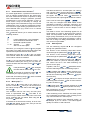
Ensure that process equipment and pressure
lines are at atmospheric pressure before making pressure connections.
Pressure lines must be kept as short as possible
and must not have short bends to avoid measurement errors induced by pressure line delays.
If the pressure transmitter is subjected to pressure
when it is started up, zero point checking and adjustment is not possible. In such cases, only electrical connections of the instrument should be made,
but not the pressure connections.
4.2
SP1no
Pressure lines must have a downward gradient
throughout from the pressure instrument to the process vessel / pipe. This is to prevent formation of air
/ gas pockets (for liquid applications) and liquid
plugs (for air / gas applications). If this continuous
downward gradient cannot be provided for any reason, then suitable water and / or air separation devices must be inserted into the pressure lines.
BN
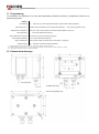
The instruments pressure ports are marked by "+"
and "-" symbols. For differential pressure applications the "+" port must be connected to the higher
pressure and the "-" port should be connected to
the lower pressure.
5
GN/YE
BK
FE
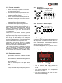
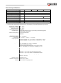
Signal +Sig
BK
Connector 2: Switch outputs
SP1com
4.2.2
BU
Carefully check the pressure-tightness of all
pressure connections before start-up.
Supply -Ub
•
BU
Ensure that process pressure is always less
than the specified safe pressure rating.
SP2com
•
WH
Ensure that the mechanical configuration and
materials of construction of the instrument are
compatible with the process media.
Signal -Sig
•
WH
The instrument should be provided with suitable protection against pressure surges (e.g.,
snubber or pulsation damper).
Internal connection
SP2no
•
Connector 1:
Supply input and Signal output
BN
•
Process connection
Supply +Ub
4.1
Starting Operation
All electrical supply, operating and measuring lines
and the pressure connections must have been correctly installed before commissioning. All supply
lines shall be arranged such that there are no mechanical forces acting on the device.
Check the leak-tightness of the pressure connections before commissioning.
5.1
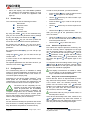
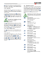
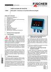
Display
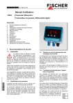
3½ Character LED Display
Switching Output 2
Switching Output1
Electrical connection
•
Only qualified technicians authorized for this
type of work should undertake installation.
•
Electrical connections must comply with relevant international, national and local regulations
and norms relating to electrical and instrumentation installations.
•
Switch off electrical power to the plant before
attempting electrical installation work of any
kind.
•
Make electrical connections to the transmitter
through a suitable energy-limiting safety device
Control keys
Measuring
unit
•
The 3½ character LED display presents the
current differential pressure in normal operating
mode.
•
The selected measuring unit is highlighted at
the right of the display.
The units represented on the screen may deviate from the actual design.