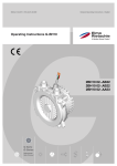
1
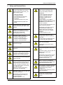
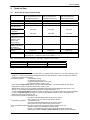
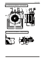
Gas-Ring
Vacuum Pumps/ -Compressors
Operating Instructions
G-Series
Types
2BH10 02- 2BH10 02- 2BH10 02_AB32
_AB22
_AA53
|
© Gardner Denver Deutschland GmbH
P.O. box 1510
D-97605 Bad Neustadt / Saale
Germany
Phone: +49 7622 392-0
Fax:
+49 7622 392-300
E-mail: [email protected]
Internet: www.gd-elmorietschle.com
All rights reserved.
Translation of the
original operating instructions
610.44431.40.000
Edition 01/2007
English
© Gardner Denver Deutschland GmbH 2007
Replication, distribution and / or editing of this document and the use and distribution of its content is
prohibited unless explicitly permitted. Violation obligates compensation for damages.
All rights reserved in case of the issue of a patent, utility patent or design patent.
Table of Contents
1
Table of Contents
1
2
3
4
Table of Contents ....................................................................................................................... 3
Safety and Residual Risks.......................................................................................................... 4
Intended Use .............................................................................................................................. 6
Technical Data............................................................................................................................ 7
4.1
Nominal and Limiting Values Pump ......................................................................................... 7
4.2
Nominal and Limiting Values Motor and Electronics ............................................................... 8
5
Transport and Handling ............................................................................................................ 12
6
Installation and Commissioning................................................................................................ 12
6.1
Mounting ................................................................................................................................ 12
6.2
Connection ............................................................................................................................. 14
6.2.1
Electrical Connection (Motor)............................................................................................ 14
6.2.1.1
G_100 for external electronics..................................................................................... 15
6.2.1.2
G_100 with integrated electronics ............................................................................... 20
6.2.2
Pipe / hose connections (pump) ....................................................................................... 22
6.3
Commissioning....................................................................................................................... 24
7
Operation .................................................................................................................................. 25
8
Servicing ................................................................................................................................... 26
8.1
Maintenance........................................................................................................................... 27
8.1.1
Cleaning ............................................................................................................................ 27
8.1.2
Inspection.......................................................................................................................... 28
8.1.3
Lubrication......................................................................................................................... 28
8.2
Repair / Troubleshooting........................................................................................................ 28
9
Shutting Down and Measures for Prolonged Standstill ............................................................ 30
10
Manufacturer's Declaration / Declaration of Conformity........................................................... 31
© Gardner Denver Deutschland GmbH
3 / 31
610.44431.40.000
Safety and Residual Risks
2
Safety and Residual Risks
Before beginning to work on the
G_100 or the system carry out the
following steps for both the G_100
and the entire system
Operation of the G_100 only with the
pipes / hoses connected to the
suction and delivery branches!
WARNING!
In case of operation with open
suction or delivery branches
(drawing-in of gases from or
discharge of gases into the
surroundings)
a piece of pipe or hose with a
length of at least 120 mm must by
all means be connected to the
branch in question
in order to prevent the impeller from
being reached by fingers!
switch off electricity,
lock against restart,
ensure absence of electricity,
ground and short-circuit
installation,
- cover or bar adjacent live parts,
-
-
depressurise both pipes and
pump.
Do not wear long, loose hair! Use
a hair net! Never wear wide, loose
clothes!
Disassembly of the pipes / hoses
connected to the suction and
delivery branches only after the
impeller has come to a complete
standstill!
Consider impeller run-out!
Transport and handling as well as
assembly and disassembly may be
carried out by trained and
responsible personnel only!
Do not reach into the G_100
through open suction or delivery
branches!
Do not insert any objects into the
G_100 through the openings!
Operation of the G_100 only
- with the gases as indicated in
section 3, "Intended Use"!
- with the values as indicated in
section 4, "Technical Data"!
Operation of the G_100 only with the
motor cap assembled!
Check pipes/hoses and vessels for
sufficient strength!
Disassembly of the motor cap is
prohibited.
For protection against the running
rotor provide a guard in front of the
motor!
Check pipe / hose connections for
tightness!
Operation of the G_100 only with the
guard in front of the motor
assembled!
Operation of the G_100 only when
completely assembled and securely
fastened to the mounting surface!
Disassembly of the guard in front of
the motor only after the rotor has
come to a complete standstill!
Consider rotor run-out!
Check fasteners for secure fixing at
regular intervals!
Work on electrical installations
may be carried out by trained and
authorised electricians only!
After loosening clampings and
fastening elements some parts and
components are only held in place
by their centrings or seatings or are
no longer held in place at all so that
they might fall down.
Take the necessary care during
disassembly and assembly!
The electrical connections must be
surrounded by a housing which is
proof against foreign bodies,
humidity, etc.!
Consider the life expectancy of the
seals and gaskets!
Operation of the G_100 only with the
pump lid assembled!
Ensure that no foreign bodies,
humidity, etc. enter the motor
interior!
Disassembly of the pump lid only
after the impeller has come to a
complete standstill!
Consider impeller run-out!
© Gardner Denver Deutschland GmbH
4 / 31
610.44431.40.000
Safety and Residual Risks
Danger zone:
The vicinity of the unit during
operation with open suction or
delivery branches (drawing-in of
gases from or discharge of gases
into the surroundings)
Hazard:
• Injuries due to contact with
pressurised fluids or due to
sudden acceleration of parts.
• Injuries due to parts thrown out of
the unit.
Protective measures:
• Ensure that fluids discharged into
the surroundings are not expelled
close to people (e.g. work stations
on machines)!
• During work on or near the unit
wear personal protective
equipment!
For heat dissipation and cooling
provide a minimum distance of
15 mm on each side
except for the pump lid side on
which a smaller distance of at
least 2 mm is permissible!
Burning and scalding hazard due to
hot surfaces of the G_100!
Do not touch during operation! Let
the unit cool after shut-down!
Provide a guard against accidental
contact!
i
The motor of the G_100 including its
connecting leads must be protected
against electrostatic discharge
(ESD).
Do not remove the ESD-prevention
bag surrounding the lead ends until
right before carrying out the
electrical connection (attaching the
connector, connecting to a terminal
strip, or the like)!
Carry out the electrical connection
using the appropriate ESDprevention equipment!
Residual Risks
Danger zone:
Hot surface.
Hazard:
Burning / scalding hazard.
Protective measures:
Attach warning sign "Warning of hot
surface".
Danger zone:
Impeller of the pump can be reached
through open suction or delivery
branches.
Hazard:
• Severing of limbs.
• Drawing-in and entanglement of
hair.
Protective measures:
• Operation only with the pipes /
hoses connected to the suction
and delivery branches!
In case of operation with open
suction or delivery branches
(drawing-in of gases from or
discharge of gases into the
surroundings) a piece of pipe or
hose with a length of at least
120 mm must by all means be
connected to the branch in
question!
• Use a hair net!
© Gardner Denver Deutschland GmbH
5 / 31
610.44431.40.000
Intended Use
3
Intended Use
These operating instructions
• must be completely read and understood by
all operating and servicing personnel before
beginning to work with or on the G_100,
• must be strictly observed,
• must be available at the site of operation of
the G_100,
• applies to Gas-Ring Vacuum Pumps /
Compressors, type G_100,
• contains instructions bearing on transport
and handling, installation, commissioning,
operation, servicing, shut-down, and
storage of the G_100.
• are intended for industrial applications
• are designed for continuous operation;
in case of increased turn-on frequency or
increased intake and ambient temperature
the limiting overtemperature of the winding
and the bearings must not be exceeded
(operation only according to Fig. 3,
"Permissible total differential pressure /
conversion factor", p. 11).
When operating the G_100 it is imperative to
observe the limiting values given in section 4,
"Technical Data".
The operating and servicing personnel working
with or on the G_100:
• must be trained and authorised for the work
to be carried out.
• Work on electrical installations may be
carried out by trained and authorised
electricians only.
Foreseeable Misuse
It is prohibited
• to use the G_100 in applications other than
industrial applications,
• to use the G_100 in areas where explosive
atmosphere might occur,
• to extract, to deliver and to compress
explosive, flammable, aggressive or toxic
fluids,
• to operate the G_100 with values other than
those given in section 4, "Technical Data".
The G_100
• are single-stage gas-ring vacuum pumps /
compressors
• are machines used to generate vacuum or
overpressure
• are used to extract, to deliver and to
compress the following pumped gases:
- air
- other gases,
which are not explosive, flammable,
aggressive, or toxic
- The pumped gases must not contain any
solid bodies or impurities;
those must be separated before entering
the unit by means of a filter.
• exist in four fundamental designs1:
- 2BH10 02-0AB32:
hose connection
with enclosed motor
and integrated electronics
- 2BH10 02-0AB22:
hose connection
with enclosed motor
and integrated electronics
- 2BH10 02-0AA53:
hose connection
with enclosed motor
external electronics
- 2BH1002-1….:
flange connection
1
Any unauthorised modifications of the G_100
are prohibited for safety reasons.
Maintenance work is only allowed to the extent
described in these operating instructions.
Any further maintenance work as well as repair
work may only be carried out by companies
authorised by the manufacturer (please
contact your sales engineer).
i
IMPORTANT!
The G_100 is a component
intended to be incorporated in a
machine or system. It is delivered
for this purpose to manufacturers
of such machinery or systems
(OEMs) only.
i
IMPORTANT!
The installation of the G_100 in
your machine or system must be
carried out in keeping with the
requirements on electromagnetic
compatibility according to the
EMC Directive.
In order to determine the design of your G_100
refer to the type number (MLFB) on the rating
plate.
© Gardner Denver Deutschland GmbH
6 / 31
610.44431.40.000
Technical Data
4
4.1
Technical Data
Nominal and Limiting Values Pump
Type (MLFB)
Weight
Dimensions
Sound level2
max. permissible
total differential
pressure3 at +15°C
• vacuum pump
operation4
• compressor
operation5
max. permissible
differential pressure
between pump
interior and
surroundings
max. permissible
intake and ambient
temperature
max. permissible
speed6
bearing life L107
electrical data
2BH10 02-_AB32
(with enclosed motor and
integrated electronics)
1,2 kg
see Fig. 1 & 2 / p. 9/10
48 dB(A)
2BH10 02-_AB22
(with enclosed motor,
integrated electronics)
1,2 kg
see Fig. 1 & 2 / p. 9/10
51 dB(A)
2BH10 02-_AA53
(with enclosed motor,
external electronics)
1,5 kg
see Fig. 1 & 2 / p. 9/10
55 dB(A)
100 mbar
105 mbar
185 mbar
105 mbar
105 mbar
190 mbar
0.15 bar
0.11 bar
0.15 bar
+ 40°C
+ 40°C
+ 40°C
9,500 min-1
12,000 min-1
15,000 min-1
20,000 h
20,000 h
20,000 h
see section 4.2, "Nominal and Limiting Values Motor and Electronics", p. 8,
and section 6.2.1, "Electrical Connection (Motor)", p. 14
Max. permissible dynamic load of the G_100 due to vibrations from outside:
Vibration frequency
< 6.3 Hz
6.3 Hz ... 63 Hz
> 63 Hz
Vibration value
Vibration displacement
Vibration velocity
Vibration acceleration
s ≤ 0.16 mm
vrms ≤4.5 mm/s
a ≤ 2.55 m/s²
2
Surface sound pressure level (DIN 45 635, Part 13), measured at a distance of 1 m at an operating point
of approx. 2/3 of the permissible total differential pressure with the pipes / hoses connected and without
vacuum or pressure limiting valve.
3
Permitted only with:
unobstructed cooling,
an operating voltage of 24 V,
a speed reference value of 10 V and
left-handed rotation of the G_100.
The indicated temperature refers to the gas intake temperature. It is assumed that the gas intake
temperature equals the ambient temperature of the G_100.
IMPORTANT: For the max. permissible total differential pressure at temperatures other than +15°C
see Fig. 3, "Permissible total differential pressure / conversion factor", p. 11.
In case of increased throttling inside the suction or delivery pipe a pressure relief valve must be provided.
In case of reduced speeds by means of a lower speed reference value the max. permissible total
differential pressures change as well.
4
Vacuum pump operation: extraction of air
having the indicated temperature at the suction branch
and a pressure of 1013 mbar at the delivery branch.
5
Compressor operation: compression of air
having the indicated temperature at the suction branch
and a pressure of 1013 mbar at the suction branch.
6
Max. permissible speed due to the mechanical components and the design of the unit..
7
For:
operation within the permissible operating range,
the max. permissible dynamic load due to vibrations from outside and
fastening by means of rubber / metal elements (available as accessories).
© Gardner Denver Deutschland GmbH
7 / 31
610.44431.40.000
Technical Data
4.2
Nominal and Limiting Values Motor and Electronics
G_100 with integrated electronics
Type 2BH10 02-_AB32
Quantity
Voltage range
Nominal voltage
Max. input current
Nominal speed
Motor rating
Speed control range
Internal resistance at desired speed
Permissible ambient temperature
Relative humidity
Value
14...28
24
4,5
9500
90
1000 - 9500
70
-10 ... +40
max. 95
Unit
V DC
V DC
A
min-1
W
min-1
Ω
°C
%
Type 2BH10 02-_AB22
Quantitiy
Voltage range
Nominal voltage
Max. input current
Nominal speed
Motor rating
Speed control range
Internal resistance at desired speed
Permissible ambient temperature
Relative humidity
Value
14...28
24
5,2
11500
115
1000 - 12000
70
-10 ... +40
max. 95
Unit
V DC
V DC
A
min-1
W
min-1
Ω
°C
%
Value
38...52
48
7
15000
300
1000 - 15000
70
-10 ... +40
max. 95
Unit
V DC
V DC
A
min-1
W
min-1
Ω
°C
%
G_100 with external electronics / Drivecontrol VT-D
Typ 2BH10 02-_AA53
Quantity
Voltage range
Nominal voltage
Max. input current
Nominal speed
Motor rating
Speed control range
Internal resistance at desired speed
Permissible ambient temperature
Relative humidity
Due to the PWM control of the electronics the power supply unit is loaded with short, high current
pulses. For this reason the supply voltage must be blocked or filtered by means of a capacitor (low
ESR type, suitable type for high frequencies, high current switching, > 1000 µF) for noise suppression.
Usually this capacitor is part of the power supply unit. Switch-mode power supplies, however, are
often provided with a capacitor of only very small capacitance at the output so that this kind of pulses
result in interference. In this case an additional capacitor must be connected as close to the motor as
possible.
© Gardner Denver Deutschland GmbH
8 / 31
610.44431.40.000
Technical Data
Fig. 1: Dimensions of the 2BH1002-0…. (hose connection)
Fig. 2: Dimensions of the 2BH1002-1…. (flange connection)
© Gardner Denver Deutschland GmbH
9 / 31
610.44431.40.000
Technical Data
Hose connection
B
B1
B2
C
D
∅ d1
∅ d2
E
F
G
G1
K
∅ R2
2BH1002-0AB32
145
133
121
95
72
20
19
53
72
11
1
450
4,2
2BH1002-0AB22
145
133
121
95
72
20
19
53
72
11
1
450
4,2
2BH1002-0AA53
145
133
121
95
72
20
19
53
92
11
1
450
4,2
2BH1002-1AB32
145
133
121
95
60
20
19
53
72
11
1
450
4,2
2BH1002-1AB22
145
133
121
95
60
20
19
53
72
11
1
450
4,2
2BH1002-1AA53
145
133
121
95
60
20
19
53
92
11
1
450
4,2
Flange connection
© Gardner Denver Deutschland GmbH
10 / 31
610.44431.40.000
Technical Data
Fig. 3: Permissible total differential pressure / conversion factor
1.01
1
Conversion factor
0.99
0.98
0.97
0.96
0.95
0.94
0.93
0.92
0.91
-20
-10
0
10
20
30
40
50
Gas intake and ambient temperature t [°C]
For the permissible total differential pressure at an intake and ambient temperature of +15°C see the
table in section 4.1, "Nominal and Limiting Values Pump", p. 7.
In order to calculate the permissible total differential pressure for other intake and ambient
temperatures proceed as follows:
- Find out your system-dependent gas intake and ambient temperature.
- Establish the conversion factor valid for these conditions by means of the above diagram.
(In order to do so mark your intake and ambient air temperature on the temperature axis. Draw a
vertical line from this value to the point of intersection with the curve. Now draw a vertical line from
the point of intersection to the conversion-factor axis where you can read the conversion factor then.)
- Multiply the established conversion factor with the max. permissible total differential pressure at
15°C as given in the table in section 4.1, "Nominal and Limiting Values Pump", p. 7.
- The result will be a pressure value. This is the max. permissible total differential pressure valid
for your G_100 at your system-dependent intake and ambient temperature.
© Gardner Denver Deutschland GmbH
11 / 31
610.44431.40.000
Transport and Handling / Installation and Commissioning
5
Transport and Handling
Packaging:
On delivery the G_100 is packed up in a
cardboard box. When there is no connector
attached to the electrical connecting cable the
lead ends are surrounded by an ESDprevention bag.
6
i
IMPORTANT!
The motor of the G_100 including
its connecting leads must be
protected against electrostatic
discharge (ESD).
Do not remove the ESDprevention bag surrounding the
lead ends until right before
carrying out the electrical
connection (attaching the
connector, connecting to a
terminal strip, or the like)!
Installation and Commissioning
6.1
For the arrangement of the G_100 and its
components see
Mounting
-
Fig. 4: General view G_100
For the space required and the arrangement of
the mounting holes required for fastening the
G_100 to the mounting surface please refer to
3
1
Fig. 4: General view G_100.
2
4
-
Fig. 1: Dimensions of the , p. 9/10
The G_100 must be mounted as follows:
- the shaft being in any position,
- such as not to exceed the vibration values
given in section 4, "Technical Data",
- for heat dissipation and cooling
provide a minimum distance of 15 mm on
each side
except for the pump lid side on which a
smaller distance of at least 2 mm is
permissible (in case of mounting using
rubber / metal elements, see p. 13).
4
CAUTION!
Choose the place of installation /
the mounting surface of the
G_100 so that there is no hazard
of tripping or bumping!
5
General view G_100 (pump side)
1 Suction branch
2 Delivery branch
3 Electrical connecting cable
4 Arrows indicating delivery direction
5 Fixing lugs for fastening to a mounting
surface
© Gardner Denver Deutschland GmbH
i
12 / 31
IMPORTANT!
Do not install the G_100 close to
heating surfaces! No direct
insolation!
610.44431.40.000
Installation and Commissioning
i
CAUTION!
Lay the electrical connecting
cable so that it might not be
damaged by outer influences and
is free from tensile stress!
Sound and vibration attenuation:
- In order to reduce sound emission fasten
the G_100 only to parts or components that
do not conduct or emit sound easily (e.g.
thin walls, plates).
- Provide sound-absorbing shims, termed
rubber / metal elements (available as
accessories). These are rubber pads
placed between the four fixing lugs and the
mounting surface and used to absorb
vibrations.
© Gardner Denver Deutschland GmbH
IMPORTANT!
During operation the surface of
the G_100 might have high
temperatures of more than
100°C!
Temperature-sensitive parts or
components, e.g. electrical wires
or cables or electronic
components must not be in
contact with or fastened to these
surfaces!
CAUTION!
Burning and scalding hazard
due to hot surfaces of the
G_100 during operation!
Provide a guard against
accidental contact.
Place the rubber / metal elements (rubber
pads) between the fixing lugs (Fig. 4, # 6) and
the mounting surface.
Fasten the G_100 to the mounting surface via
the fixing lugs using four suitable bolts or nuts.
Property class of the bolts or nuts: 8.8
according to ISO 898.
Secure the four fixing bolts against
unintentional loosening due to vibrations.
13 / 31
610.44431.40.000
Installation and Commissioning
6.2
6.2.1
Connection
Electrical Connection (Motor)
WARNING!
Work on electrical installations may be carried out by trained and authorised
electricians only!
WARNING!
Before beginning any electrical work on the G_100 or the system carry out the
following steps for both the G_100 and the entire system
-
switch off electricity,
lock against restart,
ensure absence of electricity,
ground and short-circuit installation,
cover or bar adjacent live parts,
WARNING!
The connecting terminals
- must be installed such that they cannot be touched during operation!
- must be surrounded by a housing which is proof against foreign bodies,
humidity, etc.! Consider the life expectancy of the seals and gaskets!
- must be separated by sufficient distances (mind protruding wire ends)!
WARNING!
Ensure that no foreign bodies, humidity, etc. enter the motor interior!
The G_100 is operated using an electronics for speed and direction of rotation control.
Depending on where this electronics is located (inside or outside the G_100),
two types of the G_100 are distinguished:
• for external electronics (see section 6.2.1.1):
- 2BH10 02-0AA53
• with integrated electronics (see section 6.2.1.2):
2BH10 00-0AB32
2BH10 02-0AB22
In order to determine the type of your G_100 refer to the type number (MLFB) on the rating plate.
© Gardner Denver Deutschland GmbH
14 / 31
610.44431.40.000
Installation and Commissioning
i
6.2.1.1
IMPORTANT!
The motor of the G_100 including its connecting leads must be protected against
electrostatic discharge (ESD).
Do not remove the ESD-prevention bag surrounding the lead ends until right before
carrying out the electrical connection (attaching the connector, connecting to a terminal
strip, or the like)!
Carry out the electrical connection using the appropriate ESD-prevention equipment!
G_100 for external electronics
With this type the electronics is located outside the G_100. It is connected via the electrical connecting
cable.
i
IMPORTANT!
The main or operating direction of rotation of the G_100 is the counter-clockwise
rotation,
given by the arrow indicating the direction of rotation on the pump lid
(see p. 12, Fig. 4, # 5).
Only with the counter-clockwise rotation the nominal values will be achieved.
Clockwise rotation is only permissible in special cases.
In this instance the G_100 will not achieve its full output.
i
i
i
IMPORTANT!
The connecting cable between the G_100 and the external electronics must have a
length of at maximum 0.5 m!
IMPORTANT!
When switching off the G_100 or rapidly reducing its speed a current feed into the
mains might occur.
This can be prevented by inserting a diode (Schottky diode, size 10 A) in the 48-V
supply lead (+VCC).
IMPORTANT!
Provide good cooling of the surroundings of the motor and the external electronics (e.g.
mounting on a good thermal conductor, sufficient ventilation)!
In case of temperatures of > 50°C, measured at the surface of the external electronics
(Drivecontrol), the output power of the pump might be reduced.
© Gardner Denver Deutschland GmbH
15 / 31
610.44431.40.000
Installation and Commissioning
Purchasing the external electronics (Drivecontrol) along with the G_100
For the order no. of this option please refer to our catalogue.
The design of the external electronics (Drivecontrol) is as follows:
Fig. 5: External electronics: block diagram of the control principle
+VCC
Mode of operation
A
B
Output stage
PWM
generation
Speed controller
ndes
L1
+
L2
L3
Commutation
logic
MOTOR
Current
measurement
Speed
evaluation
Gnd
Rotor position detector
RLG1, RLG2, RLG3
MF pin
GndHall
+ VHall
Internal
signal processing
Motor connection (X4)
Supply voltage / control signal
connection (X3)
external electronics
(commercial component)
External electronics
Block diagram of the control principle
Colours of the connecting leads of the
motor:
RLG1
green
L1
brown
GndHall
L2
violet
RLG2
white
+VHall
RLG3
grey
L3
yellow
© Gardner Denver Deutschland GmbH
16 / 31
black
red
610.44431.40.000
Installation and Commissioning
Supply voltage / control signal connection side:
The connector for supply voltage / control signal connection (connector X3) is shown in Fig. 7.
On the supply voltage / control signal connection side the assignment is as follows:
Symbol
A
Description
Mode of operation
+UB
nSoll (S+)
+ Operating voltage
Not used
Speed reference value
B
IST
Gnd
S-
States:
1 (High): 5 ... max. 30 V
0 (Low): < 0,5 V
38 ... 52 V
Control voltage: 0 ... 10 V
Reference value of the desired speed of
the G_100.
Mode of operatione
States:
1 (High): 5 ... max. 30 V
0 (Low): < 0,5 V
Actual speed (optional) Open Collector output
Here the rotor speed can be read
- Betriebsspannung
0V
Ground Set Value input 0 V
Lead colour Pin
white
Pin 1
red
violet
green
Pin 2
Pin 3
Pin 4
grey
Pin 5
yellow
Pin 6
black
brown
Pin 7
Pin 8
Via the digital control inputs A and B the direction/mode of operation is determined.
The following states are possible:
Level A
0
0
Level B
0
1
1
0
1
1
Mode of operation
Output stage disabled (no current).
Counter-clockwise rotation
(according to the arrow indicating the direction of rotation on the pump lid, see
p. 12, Fig. 4, # 5):
Main / operating direction of rotation of the G_100!
Clockwise rotation
(opposed to the arrow indicating the direction of rotation on the pump lid,
see p. 12, Fig. 4, # 5):
Breaking
Please take also note of the following data:
Wire cross section of the connecting cable
Control current on the supply voltage /
control signal connection side
0.5 mm²
max. 9 A
Motor connection side:
The connector for motor connection (connector X4) is shown in Fig. 7.
On the motor connection side the assignment is as follows:
Symbol
L1
L2
L3
Description
Motor phase 1
Motor phase 2
Motor phase 3
RPD1
RPD2
RPD3
Hall signal 1
Hall signal 2
Hall signal 3
+VHall
GndHall
Hall supply
Hall supply
© Gardner Denver Deutschland GmbH
Terminals of the motor windings.
Operating voltage: 0,9 * Uvv
max. winding peak current: 13 A
max. winding temperature: 115°C
Rotor position detectors.
Hall ICs with open collector output.
They must be wired to an external pull-up
resistor.
Feeder line of the hall ICs.
17 / 31
Lead colour
brown
violett
yellow
Pin
Pin 6
Pin 5
Pin 1
green
white
grey
Pin 4
Pin 3
Pin 8
red
black
Pin 2
Pin 7
610.44431.40.000
Installation and Commissioning
Fig. 6: External electronics
92
112
13
Drivecontrol VT-D
PAPST
3
∅ 6,5
84
Gardner Denver elmo technology-Ident.-Nr.:
519_00082_01_000
80
Control signal
connector
(X3)
Motor
connector
(X4)
Fig. 7: Connector pin assignment and mating connector
Control signal connections Motor connections
(X3)
(X4)
Mating connector type:
MOLEX - 39-01-2085
Slot for lug
Slot for lug
RLG3 Gnd
RLG1
L1
L2
S-
Gnd
IST
B
8
7
6
5
8
7
6
5
4
3
2
1
4
3
2
1
+Ub
A
RLG2
+U Hall
© Gardner Denver Deutschland GmbH
L3
lug
Mating connector type:
MOLEX - 39-01-2085
S+
Not
used
18 / 31
5
6
7
8
1
2
3
4
Mating connector
(connected to motor cable)
610.44431.40.000
Installation and Commissioning
If there is no connector (mating connector to the external electronics) connected to the motor cable of
the G_100, the loose lead ends are surrounded by an ESD-prevention bag. In this case, the socket
connector must first be connected to the motor cable.
i
IMPORTANT!
The motor of the G_100 including its connecting leads must be protected against
electrostatic discharge (ESD).
Do not remove the ESD-prevention bag surrounding the lead ends until right before
carrying out the electrical connection (attaching the connector, connecting to a terminal
strip, or the like)!
Carry out the electrical connection using the appropriate ESD-prevention equipment!
The scope of supply of the external electronics (Drivecontrol VT-D) includes a connnector with a 300
mm wiring harness to connect the Drivecontrol to the supply voltage and control voltage.
In order to meet the requirements bearing on electromagnetic compatibility a suitable EMI filter
(e.g. CORCOM, Type 6ET1, 10A) must be connected in series with the external-electronics. The
connecting cable between the EMI filter and the G_100 must have a length of at maximum 0,3 m..
© Gardner Denver Deutschland GmbH
19 / 31
610.44431.40.000
Installation and Commissioning
6.2.1.2
G_100 with integrated electronics
With this type the electronics is located inside the motor.
i
IMPORTANT!
With the integrated-electronics type G_100 the electronics is particularly sensitive to
overheating!
It is imperative to ensure sufficient heat dissipation and cooling!
On delivery the integrated-electronics type G_100 is not equipped with a connector at the connecting
cable. In this instance the operator can, according to the requirements of the system, connect a
connector at his option, connect the terminals to a terminal strip, etc.
The electrical connection is to be carried out:
- according to the applicable national and local laws and prescriptions
- according to the applicable system-dependent prescriptions and requirements
- according to the applicable prescriptions of the utility company
Via the motor connecting cable the supply voltage as well as the different control signals are applied to
the integrated electronics.
For the assignment of the leads or strands please refer to Fig. 8 as well as the following table.
Fig. 8: Connection of the integrated electronics type
Cable
old version
pink
yellow
green
white
grey
blue
brown
red
Lead colour
Cable
new version
red
black
green
white
grey
blue
---
Assignment
+VCC
Gnd
ndes
A
B
nact
not connected
not connected
G_100G
ELMO
2BH10
®
© Gardner Denver Deutschland GmbH
20 / 31
610.44431.40.000
Installation and Commissioning
Symbol
Description
Level
+VCC
Gnd
DC operating voltage
DC operating voltage,
reference potential for all signals
Speed reference value:
Reference value of the desired speed
of the ELMO® G 2BH10.
Frequency output representing the
actual speed:
open collector signal which must be
wired to an external pull-up resistor.
Output frequency / motor speed ratio:
1 Hz = 10 min-1
Control signals A and B are digital
inputs.
Broad voltage-range input compatible
with TTL / PLC signals.
In all four possible combinations:
24 V (max. 28 V)
0V
Lead colour
Cable
Cable
old version
new version
pink
red
yellow
black
0 ... 10 V DC
green
green
Open collector
max. 24 V / 10 mA
blue
blue
Low (0): < 0.5 V DC
High (1): > 4 V DC
white
grey
white
grey
---
brown
red
---
ndes
nact
A
B
A B Function
0 0 Motor disabled (no current)
0 1 CCW rotation
1 0 CW rotation
1 1 Motor disabled
not connected
not connected
---
In order to meet the requirements bearing on electromagnetic compatibility an EMI filter from
Messrs CORCOM, Type 6ETI F7003, 6A, must be connected in series with the integrated-electronics
type G_100. The connecting cable between the EMI filter and the G_100 must have a length of at
maximum 0.5 m.
i
IMPORTANT!
The main or operating direction of rotation of the G_100 is the counter-clockwise
rotation,
given by the arrow indicating the direction of rotation on the pump lid
(see p. 12, Fig. 4, # 5).
Only with the counter-clockwise rotation the nominal values will be achieved.
Clockwise rotation is only permissible in special cases.
In this instance the G_100 will not achieve its full output.
i
i
IMPORTANT!
The connecting cable between the G_100 and the external electronics must have a
length of at maximum 0.5 m!
IMPORTANT!
When switching off the G_100 or rapidly reducing its speed a current feed into the
mains might occur.
This can be prevented by inserting a diode (Schottky diode, size 6A) in the 24-V supply
lead (+VCC).
© Gardner Denver Deutschland GmbH
21 / 31
610.44431.40.000
Installation and Commissioning
6.2.2
Pipe / hose connections (pump)
Fig. 9: General view G_100
3
1
2
4
4
General view G_100 (pump side)
6 Suction branch
7 Delivery branch
8 Electrical connecting cable
9 Arrows indicating delivery direction
10 Fixing lugs for fastening to a mounting
surface
5
On delivery the suction and delivery branches
of the G_100 are sealed up in order to prevent
foreign bodies from entering the pump.
Do not remove the seals until right before
connecting the pipes / hoses.
i
The pumped gases / vapours are taken in via
the suction branch and are expelled via the
delivery branch.
The suction branch (Fig. 9, # 1) is indicated
by an arrow pointing into the pump. Connect
the suction pipe to this branch.
The delivery branch (Fig. 9, # 2) is indicated
by an arrow pointing out of the pump. Connect
the delivery pipe to this branch.
IMPORTANT!
The G_100 must not be operated
with the suction or delivery
branches sealed up or jammed!
i
For the arrangement of the branches see Fig. 9,
"General view ".
The operating direction of the G_100 is
indicated by means of arrows:
- The direction of rotation is indicated by an
arrow on the pump casing.
- The delivery direction is indicated by arrows
on the suction and delivery branches.
i
Make sure to connect the pipes / hoses so that
the G_100 will not be subject to any stress or
strain.
IMPORTANT!
The main or operating direction
of rotation of the G_100 is the
counter-clockwise rotation,
given by the arrow indicating the
direction of rotation on the pump lid
(see Fig. 9, # 5).
Only with the counter-clockwise
rotation the nominal values will be
achieved.
WARNING!
Rotating impeller - hazard of
severing limbs!
In case of operation with open
suction or delivery branches
(drawing-in of gases from or
discharge of gases into the
surroundings)
a piece of pipe or hose with a
length of at least 120 mm must
by all means be connected to
the branch in question
in order to prevent the impeller
from being reached by fingers!
Clockwise rotation is only
permissible in special cases. In this
instance the G_100 will not achieve
its full output.
© Gardner Denver Deutschland GmbH
IMPORTANT!
These instructions apply to the
counter-clockwise rotation!
In case of clockwise rotation the
suction and delivery branches
are exchanged!
22 / 31
610.44431.40.000
Installation and Commissioning
i
IMPORTANT!
The pipes / hoses must be
attached in a secure and tight
fashion.
They must be locked against
unintentional loosening e.g. due
to vibrations, thermal expansion,
etc.
WARNING!
Check pipes / hoses and vessels
for sufficient strength!
WARNING!
Check pipe / hose connections
for tightness!
i
IMPORTANT!
Provide a shut-off device and / or
a means for depressurisation in
both the suction and the delivery
pipes.
© Gardner Denver Deutschland GmbH
23 / 31
610.44431.40.000
Installation and Commissioning
6.3
Commissioning
WARNING!
Operation of the G_100 only:
- with the pump lid assembled
- with the pipes / hoses connected to the suction and delivery branches or
- in case of operation with open suction or delivery branches (drawing-in of
gases from or discharge of gases into the surroundings)
with a piece of pipe or hose having a length of at least 120 mm connected to
the branch in question
- with bearing end housing
WARNING!
Do not reach into the G_100 through open suction or delivery branches!
Do not insert any objects into the G_100 through the openings!
i
IMPORTANT!
The G_100 must not be operated with the suction or delivery branches sealed up
or jammed!
WARNING!
Before start-up
- check pipes / hoses and vessels for sufficient strength!
- check pipe / hose connections for tightness!
-
check fasteners for secure fixing
Proceed as follows:
-
-
-
Make sure
• that the suction and delivery pipes are correctly connected,
• that in case of operation with open suction or delivery branches (drawing-in of gases from or
discharge of gases into the surroundings)
a piece of pipe or hose having a length of at least 120 mm is connected to the branch in
question in order to prevent the impeller from being reached by fingers.
• that the suction and delivery pipes are not jammed,
• that all fasteners are properly tightened,
• that the correct voltage and current are applied.
Set the control voltage serving as speed reference and applied to ndes to 0 V at first.
Turn on the indicated operating voltage.
Now increase the control voltage serving as speed reference and applied to ndes (0 to 10 V) to your
desired value or the value given on the data sheet.
By means of this speed control the operating point of the G_100 is adapted to the operating point
of the system.
Check the connections for tightness (ensure that there is no fluid leakage).
© Gardner Denver Deutschland GmbH
24 / 31
610.44431.40.000
Operation
7
Operation
WARNING!
Operation of the G_100 only:
- with the pump lid assembled
- with the pipes / hoses connected to the suction and delivery branches or
- in case of operation with open suction or delivery branches (drawing-in of
gases from or discharge of gases into the surroundings)
with a piece of pipe or hose having a length of at least 120 mm connected
to the branch in question
- with the bearing end housing
i
IMPORTANT!
The G_100 must not be operated with the suction or delivery branches sealed
up or jammed!
CAUTION!
Burning and scalding hazard due to hot surfaces of the G_100!
Do not touch during operation!
WARNING!
Before start-up and at regular intervals
- check pipes / hoses and vessels for sufficient strength!
- check pipe / hose connections for tightness!
-
check fasteners for secure fixing
Speed control:
During operation the speed of the G_100 can be modified. This allows to adapt the operating point of
the G_100 to changes in the operating point of the system.
In order to do so adjust the control voltage applied to ndes within a range of 0 to 10 V.
© Gardner Denver Deutschland GmbH
25 / 31
610.44431.40.000
Servicing
8
Servicing
WARNING!
Before beginning to work on the G_100 or the system carry out the following
steps for both the G_100 and the entire system
-
switch off electricity,
lock against restart,
ensure absence of electricity,
ground and short-circuit installation,
cover or bar adjacent live parts,
-
depressurise both pipes and pump.
WARNING!
Disassembly of
- the pump lid
- the pipe / hose connections
- the guard in front of the motor
only after the impeller and the rotor have come to a complete standstill!
Consider run-out!
Disassembly of
the bearing end housing is prohibited!
CAUTION!
Burning and scalding hazard due to hot surfaces of the G_100!
Let the unit cool after shut-down!
WARNING!
Do not reach into the G_100 through open suction or delivery branches!
Do not insert any objects into the G_100 through the openings!
CAUTION!
After loosening clampings and fastening elements some parts and
components are only held in place by their centrings or seatings or are no
longer held in place at all so that they might fall down.
WARNING!
Before recommissioning
- completely re-assemble the G_100
- check if all fasteners have been re-assembled and tightened
- check pipes / hoses and vessels for sufficient strength
- check pipe / hose connections for tightness
WARNING!
Work on electrical installations may be carried out by trained and authorised
electricians only!
© Gardner Denver Deutschland GmbH
26 / 31
610.44431.40.000
Servicing
8.1
Maintenance
8.1.1
Cleaning
Exterior:
In case of lint or dust on the pump:
Clean the entire surface of the G_100 wiping it
with a wet cloth.
-
i
Interior:
- See also Fig. 10: Disassembly / assembly
of the pump lid
- Disassemble pump lid (# 1).
In order to do so loosen the four bolts (# 2)
and carefully pull off the lid in axial direction
(see arrow) so that the pin (# 3) is not bent.
i
Remove lint using e.g. a pair of tweezers.
-
IMPORTANT!
Don not detach the impeller
nut (# 4)! Do not disassemble
the impeller (# 5)!
Otherwise, inside the motor the
rotor would be displaced by a
spring resulting in the G_100
having to be completely
disassembled and re-assembled!
IMPORTANT!
Do not use compressed air in
order to clean the pump interior
since this might result in dirt
entering the motor interior.
Re-assemble pump lid (# 1).
In order to do so carefully set the lid to the
pump so that the pin (# 3) is inserted in the
hole and thus the lid is aligned. Carefully
place the lid on the pump in axial direction
(see arrow) so that the pin is not bent.
Screw in the bolts (# 2)
securing them using Loctite 243.
Fastening torque of the bolts:
Tf = 2 Nm ± 0.2
Fig. 10: Disassembly / assembly of the
pump lid
2
1
1 Pump lid
2 Bolts
3 Impeller
axial direction
3
© Gardner Denver Deutschland GmbH
27 / 31
610.44431.40.000
Servicing
8.1.2
Inspection
8.1.3
Carry out the following tasks on the G_100 at
regular intervals:
- Fastening to the mounting surface:
Tighten fixing bolts.
Fastening torque: according to property
class 8.8 of the bolts or
nuts used as given in
ISO 898
- Cable entry:
Tighten screwed cable glands.
Fastening torques:
• on casing side:
Tf = 3.2 Nm ± 0.2
• on cable side:
Tf = 1.5 Nm ± 0.2
- Suction and delivery branches:
Check pipe / hose connections for secure
fixing and tightness.
Check pipes / hoses for tightness.
Consider material fatigue!
Replace worn parts.
8.2
i
Lubrication
IMPORTANT!
The bearings of the G_100 are
provided with a lifetime
lubrication and assembled in the
pump by adhesive bonding.
In case the bearing is damaged
or grease renewal is due the
"complete casing" (i.e. the unit
consisting of casing, stator and
two ball bearings) must be
replaced.
Repair / Troubleshooting
Fault
Motor does not start,
no motor noise.
Motor does not start,
humming noise.
Cause
At least two power supply
leads interrupted.
Remedy
Check fuses, terminals and
supply leads and close
circuit where interrupted.
No signal at control signal Apply control signals,
inputs A and B.
see section 6.2.1,
"Electrical Connection
(Motor)".
No speed reference value Set speed reference value,
given.
see section 6.2.1,
"Electrical Connection
(Motor)".
Impeller jammed.
Open pump lid, remove dirt
and foreign bodies,
as described in
section 8.1.1, "Cleaning".
Impeller damaged.
Replace impeller.
Motor bearing damaged.
Replace "complete casing"
(i.e. the unit consisting of
casing, stator and two ball
bearings).
Wrong connection of motor Check and, if necessary,
connecting leads.
correct the connection of
the motor phases and hall
signals to the drive
electronics,
see section 6.2.1,
"Electrical Connection
(Motor)".
© Gardner Denver Deutschland GmbH
28 / 31
Carried out by
Electrician
Electrician
Electrician
Qualified personnel
After-sales service
After-sales service
Electrician
610.44431.40.000
Servicing
Fault
Power consumption
too high.
No vacuum /
pressure or too little
vacuum / pressure
generated.
Cause
Winding short-circuit.
Remedy
Have winding checked.
Motor overload.
Reduce operating
pressure.
If necessary, clean filter,
silencers, and pipes.
Impeller jammed.
See "Motor does not start,
humming noise".
Leak in the system.
Seal leak in the system.
Wrong direction of rotation. Reverse direction of
rotation
by applying the correct
signals to the control signal
inputs A and B
see section 6.2.1,
"Electrical Connection
(Motor)".
Speed reference value
Adjust speed reference
representing the desired
value (ndes) within a range
speed (ndes) too low.
of 0...10 V.
Temperature of the
Provide sufficient heat
electronics too high.
dissipation and cooling.
Compressor too small.
Use bigger compressor
Density of the pumped gas Use bigger compressor
unequal 1,23 g/m³
(= density of air at 15°C
and 1013 mbar).
Impeller dirty.
Clean impeller;
if worn, have impeller
replaced.
Abnormal screeching Flow rate too high.
Increase pipe cross
noise.
section, clean pipe.
Ball bearing damaged.
Replace "complete casing"
(i.e. the unit consisting of
casing, stator and two ball
bearings).
Impeller leak.
Relative pressure between The permissible differential
compressor and
pressure between the
surroundings too high.
pump interior and the
surroundings has been
exceeded. Make sure that
the differential pressure is
not exceeded.
Current feed to the
Caused by switching off or Insert a diode (Schottky
mains.
rapidly reducing the speed diode, size 6A
of the compressor.
respectively10A) in the
24V respectively 48V
supply lead (+VCC).
© Gardner Denver Deutschland GmbH
29 / 31
Carried out by
Electrician
Qualified personnel
Qualified personnel
Qualified personnel
Electrician
Qualified personnel
Qualified personnel
Operator / qualified
personnel
Operator / qualified
personnel
Qualified personnel
/ after-sales service
Qualified personnel
After-sales service
Qualified personnel
Electrician
610.44431.40.000
Shutting Down and Measures for Prolonged Standstill
9
Shutting Down and Measures for
Prolonged Standstill
Storage conditions:
i
Ambient temperature
Relative humidity
Atmospheric pressure
IMPORTANT!
If the storage period exceeds one
year
the life expectancy of the
bearings might be reduced.
Vibrations
Measures before recommissioning after
storage:
- Make sure that there is no oxide layer on the
contacts. If necessary, remove oxide layer.
- Make sure that the insulation of the electrical
connecting cable has not become porous.
Measures after shutdown / before storage:
- Seal up the suction and delivery branches.
- Provide loose lead ends with an ESDprevention bag.
- Ensure the correct storage conditions (see
below).
© Gardner Denver Deutschland GmbH
-20°C ... +70°C
10% ... 95%
500 hPa ...
1,100 hPa
see section 4,
"Technical Data".
30 / 31
610.44431.40.000
Manufacturer's Declaration / Declaration of Conformity
10 Manufacturer's Declaration / Declaration of Conformity
EC Declaration of Conformity
Manufacturer:
Gardner Denver Deutschland GmbH
Postfach 1510
D-97605 Bad Neustadt / Saale
Product designation:
Gas-Ring Vacuum Pumps / Compressors of the 2BH10 series
models 2BH10 02-_AB32 2BH10 02-_AB22 2BH10 02-_AA53
The designated product complies with the provisions of the following European Directives:
98/37/EC
Directive 98/37/EC of the European Parliament and of the Council of 22 June 1998 on the
approximation of the laws of the Member States relating to machinery
89/336/EEC Council Directive 89/336/EEC of 3 May 1989 on the approximation of the laws of the
Member States relating to electromagnetic compatibility
The following harmonised and national standards and specifications have been applied:
Harmonised standards:
EN ISO 12100-1
2003-11-01
EN ISO 12100-2
2003-11-01
EN 563
1994-06-01
EN 1012-2
1996-04-01
EN ISO 3744
1995-09-01
EN 60034-1
2004-06-01
EN 60204-1
1997-12-01
EN 61000-6-2
2005-08-01
EN 61000-6-3
2001-10-01
Safety of machinery - Basic concepts, general principles for design;
Part 1: Basic terminology, methodology
Safety of machinery - Basic concepts, general principles for design;
Part 2: Technical principles
Safety of machinery; Temperatures of touchable surfaces;
Ergonomics data to establish temperature limit values for hot surfaces
Compressors and vacuum pumps; Safety requirements;
Part 2: Vacuum pumps
Acoustics - Determination of sound power levels of noise sources using sound pressure
Rotating electrical machines
Safety of machinery; Electrical equipment of machines;
Part 1: General requirements (IEC 204-1:1992, modified)
Electromagnetic compatibility (EMC);
Part 6-2: Generic emission standard: Immunity; Industrial environment
Electromagnetic compatibility (EMC) Part 6-3: Generic standards; Emission standard for residential, commercial and lightindustrial environments (IEC 61000-6-3:1996, modified)
EN 61000-63/A11 Electromagnetic compatibility (EMC) 2004-07-01
Part 6-3: Generic standards - Emission standard for residential, commercial and lightindustrial environments
Any modifications of the machine that have not beforehand been agreed upon and permitted by us in writing
invalidate this Declaration of Conformity.
Gardner Denver Deutschland GmbH
Bad Neustadt / Saale, 2007-01-30
Wolfgang A. Kriesten, Director Sales
Dr. Uwe Seidel, Director Operations and
Director Engineering & Development
664.44431.40.000
© Gardner Denver Deutschland GmbH
31 / 31
610.44431.40.000