1
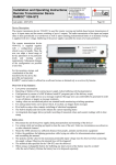
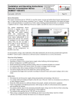
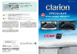
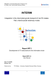
Installation and Operating Instructions
Remote Transmission Device
RAMOC® VD5-MO8
Innotas Produktions GmbH,
Friedrich-Engels-Str. 46, D-15745
Wildau
+ 49 (3375) 529649 0
+ 49 (3375) 529649 24
Email: [email protected]
www.innotas-service.de
Last update - 06.06.2014
Page 1/7
Device Description:
The remote transmission device VD5-MO8 is part of the RAMOC® product family which is intended for
mobile radio based transmission of process data and the remote switching of industrial equipment.
The VD5-MO8 is used for remote viewing and mobile-based remote transmission of up to 8 input states via
GPRS. The radio transmission of the input states is done periodically as well as upon reaching predetermined
limits or on demand.
Safety notes:
• Disconnect the unit from power supply during transportation and mounting of the device!
• Use a damp cloth and washing up liquid to clean the case of the unit. Under no circumstances use abrasives
or other chemical cleaners!
• Mount the GSM antenna in a sufficient distance from people, animals and electronic equipment
• Follow the guidelines for lightning protection while laying out cables for telecommunication equipment
and assembling the antenna.
• The technical data specified for the VD5-MO8 must be observed.
Mounting:
For mounting the device the cover has to be removed. The device has to be mounted on a flat surface with at
least two screws arranged diagonally (Note: When mounting the device on a metal plate it is recommended to
replace the antenna directly mounted on the device by an antenna, mounted at a remote place and connected
with the device by a corresponding connection cable.)
Antenna connection for
mini antenna or external
antenna
(passed out)
1. Unscrew the four screws to
remove the cover
2. Installing the device on a
flat surface
Display
DIP switches for setting
up the sensor type
Sensor Voltage 20 VDC
Common ground
Input clamps for
connection of sensors
USB-port to connect a PC
for device configuration
Cable glands for power
supply (small) and sensors
(large)
Installation and Operating Instructions
Remote Transmission Device
RAMOC® VD5-MO8
Innotas Produktions GmbH,
Friedrich-Engels-Str. 46, D-15745
Wildau
+ 49 (3375) 529649 0
+ 49 (3375) 529649 24
Email: [email protected]
www.innotas-service.de
Last update - 06.06.2014
Page 2/7
Inserting the GSM SIM card:
Note: The device must be disconnected from energy supply while inserting the GSM SIM card!
1. Remove the device cover
2. Remove upper (visible) circuit board ("Sensor connection board") by unscrewing the four screws carefully
and disconnect it from the lower circuit board ("Main Board") by
carefully disconnecting the internal flat ribbon cable.
3. Open the SIM card holder on the now visible circuit board ("Main
Board") by sliding the metal slide in the direction of cable glands
and folding up the SIM card holder. Insert the SIM card and make
sure that the chip on your SIM card points towards cable glands
and the corner recess points away from the motherboard.
4. Close SIM card holder and lock by sliding the
metal slide back.
SIM card holder. To open it push
the slide to the left.
Power supply connection:
1. Disconnect the power supply (eg remove mains plug from socket)
Observe recess in
SIM card
2. Remove the device cover
3. Remove upper (visible) circuit board ("Sensor connection board") by unscrewing the four screws carefully
and disconnect it from the lower circuit board ("Main Board") by carefully disconnecting the internal flat
ribbon cable.
4. Thread the power supply cable through the small cable entry of the case, strip a length of about 5 mm of the
cable wires and connect them to the power supply terminal clamps of the main board. Thereby observe the
right polarity.
Labelling
Colour of Terminal Clamp Meaning
+ Voltage orange
Supply voltage plus 6 .. 25 V DC
(16 V when using the accu buffering)
dark gray
Supply voltage minus (GND)
+ Accu
orange
Rechargeable battery 12V - plus polarity
-
dark gray
Rechargeable battery 12V – minus polarity (GND)
Note: The rechargeable battery circuit will only be active after its activation by the control center.
5. Tighten the small gland.
1. Unscrew the four
screws in order to
remove the upper
circuit board
2. Terminal clamps
of the power supply
Finally reconnect the internal flat ribbon cable of the upper board ("Sensor connection board") to the
„Main Board“ and mount the upper board by means of the four screws.
Installation and Operating Instructions
Remote Transmission Device
RAMOC® VD5-MO8
Innotas Produktions GmbH,
Friedrich-Engels-Str. 46, D-15745
Wildau
+ 49 (3375) 529649 0
+ 49 (3375) 529649 24
Email: [email protected]
www.innotas-service.de
Last update - 06.06.2014
Page 3/7
Sensor connection:
1. Remove the device cover
2. For each input 2 DIP-switches have to be set up according to the below illustration
1
2
0 .. 10 V-sensor
1
2
0/4 .. 20 mA-sensor
1
2
Digital Input, Counter
Illustration: Setup of DIP-switches depending on the sensor type
3. Thread the sensor cable through the large cable entry of the case.
4. Strip a length of about 5 mm of the cable wires and connect them to the terminal clamps.
5. Tighten the large gland.
Subsequently, the case cover has to be mounted, while checking the correct fit of the inserted seal.
Finally, the cable glands have to be checked and tightened if necessary.
Installation and Operating Instructions
Remote Transmission Device
RAMOC® VD5-MO8
Innotas Produktions GmbH,
Friedrich-Engels-Str. 46, D-15745
Wildau
+ 49 (3375) 529649 0
+ 49 (3375) 529649 24
Email: [email protected]
www.innotas-service.de
Last update - 06.06.2014
Page 4/7
Implementation:
After connecting the power supply the remote transmission device boots automatically. Please monitor the
display output during the boot process. The “Service-Button” allows choosing between different display
representations.
Basic screen display
RAMOC VD5-MO
GSM:
online
DS-Speicher: 22
Energievs.: ok
Line
1: Title line
2: GSM
3: DS-Speicher:
Total-DS:
4: Energievs.:
Content
Name of the shown screen display
GSM-GPRS - Status of the internet connection to the
server
Number of not yet transmitted data (measured values),
remained in the device memory
Total number of records received from the transmitters
since power on
Power supply status
Meaning of the red light "+ Us":
- lights when sensors are supplied with energy and analog measurement values are recorded
Meaning of the red light "Standby / RX":
- flickers irregularly, if PC is connected
Operation:
Generally, after booting the remote transmission device does not requires any further action. However, the
following operator actions are possible while the cover is removed:
Pressing the Service-Button in the device:
a) Short pressing: switch the display screen
b) Press and hold for at least 6s: Reset the device
Subsequently, the case cover has to be mounted,
while checking the correct fit of the inserted seal.
Service-Button
Contrast control
Maintenance:
The remote transmission device is maintenance-free. If required, the display contrast can be adjusted with the
cover removed by means of a Phillips screwdriver PH0 size. Following the contrast setting, the case cover has
to be mounted, while checking the correct fit of the inserted seal.
Repair:
Repairs may only be carried out by the manufacturer. The device must be replaced, if the remote transmission
device is defective.
Installation and Operating Instructions
Remote Transmission Device
RAMOC® VD5-MO8
Last update - 06.06.2014
Innotas Produktions GmbH,
Friedrich-Engels-Str. 46, D-15745
Wildau
+ 49 (3375) 529649 0
+ 49 (3375) 529649 24
Email: [email protected]
www.innotas-service.de
Page 5/7
Configuration of the device:
The configuration of the device is performed in two steps:
1.
Basic configuration for GSM usage:
The default setting of the device is done by the manufacturer. This ensures that the device automatically
logs in into the mobile network after the SIM-card has been inserted and the device is powered on. With
that the device can be accessed remotely for further application-specific settings in accordance with point
2. In order to do so, the customer has to specify its network / service provider with his order.
2.
Configuration of the message concept and
of inputs:
The configuration of inputs (input type, thresholds, debouncing etc.) und the message concept (reporting
cycles, event driven massages) is carried out by remote access via the Internet control center.
Installation and Operating Instructions
Remote Transmission Device
RAMOC® VD5-MO8
Innotas Produktions GmbH,
Friedrich-Engels-Str. 46, D-15745
Wildau
+ 49 (3375) 529649 0
+ 49 (3375) 529649 24
Email: [email protected]
www.innotas-service.de
Last update - 06.06.2014
Page 6/7
Specifications:
Type of the device:
RAMOC® VD5-MO8
Housing:
Plastic (polycarbonate), degree of protection IP65
Dimensions:
(W x H x D) 90 x 115 x 80 mm, plus fittings and antenna
Typical mounting height with screw, antenna and cable: 230 mm
Mounting:
Wall mounting using screws, diameter 4 mm
Inputs:
8 universal inputs, configurable as
- Analogue-Input
o Resolution 8 Bit
o prepared for sensors with:
4 .. 20 mA - Output (input resistance 125 ohms)
0 .. 20 mA - Output (input resistance 125 ohms)
0 .. 10 V - Output (input resistance 40 kohms)
other measurement ranges possible on request
- Counter-Input (digital)
o for the connection of potential-free contacts
o puls duration > 1000 ms
o contact laod < 4mA (pulsed)
- Digital-Input
o for the connection of potential-free contacts
o contact laod < 4mA (pulsed)
Other measurement ranges possible on request
Clamping range: 0,08 .. 2,5 mm²
Suitable cable diameter of M20 gland: 6 .. 12 mm
Sensor power
supply:
electronically controlled voltage generation for sensors
typically 20 V, maximum total current of all sensors: typically 100 mA
Radio:
built-in GSM modem, quad band, from Cinterion
SIM card required (3V or 1.8V)
Antenna:
external dual-band antenna with FME-connector 0 dB,
which, if required, can be replaced by an alternative antenna
Power supply:
U (nominal voltage) = 6. 25V DC, when using the rechargeable battery backup 16 V
DC, Clamping range: 0.08 .. 2.5 mm ²
Suitable cable diameter of M16 gland: 4 .. 8 mm
Installation and Operating Instructions
Remote Transmission Device
RAMOC® VD5-MO8
Innotas Produktions GmbH,
Friedrich-Engels-Str. 46, D-15745
Wildau
+ 49 (3375) 529649 0
+ 49 (3375) 529649 24
Email: [email protected]
www.innotas-service.de
Last update - 06.06.2014
Page 7/7
Current
consumption:
In normal operation typically 40 mA,
in send / receive mode briefly up to 0.5 A
Temperature range:
-25 °C .. +65 °C
Manufacturer:
Innotas Produktions GmbH
Friedrich-Engels-Str.46
D-15745 Wildau
Germany
Scope of delivery:
Remote transmission device
Standard antenna
Pluggable mains adapter
Installation and Operating Instructions
Configuration instructions
Configuration software (via web-site www.innotas-service.de)
Optional
accessories:
Solar version in a cabinet with rechargeable battery and solar controller
Control center software and hardware
External antenna
GSM-SIM-card on request