1
Installation and Operating Instructions
Remote Transmission Device
RAMOC® VD5-MO8
Innotas Produktions GmbH,
Friedrich-Engels-Str. 46, D-15745
Wildau
+ 49 (3375) 529649 0
+ 49 (3375) 529649 24
Email: [email protected]
www.innotas-service.de
Last update - 06.06.2014
Page 2/7
Inserting the GSM SIM card:
Note: The device must be disconnected from energy supply while inserting the GSM SIM card!
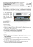
1. Remove the device cover
2. Remove upper (visible) circuit board ("Sensor connection board") by unscrewing the four screws carefully
and disconnect it from the lower circuit board ("Main Board") by
carefully disconnecting the internal flat ribbon cable.
3. Open the SIM card holder on the now visible circuit board ("Main
Board") by sliding the metal slide in the direction of cable glands
and folding up the SIM card holder. Insert the SIM card and make
sure that the chip on your SIM card points towards cable glands
and the corner recess points away from the motherboard.
4. Close SIM card holder and lock by sliding the
metal slide back.
SIM card holder. To open it push
the slide to the left.
Power supply connection:
1. Disconnect the power supply (eg remove mains plug from socket)
Observe recess in
SIM card
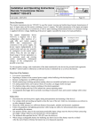
2. Remove the device cover
3. Remove upper (visible) circuit board ("Sensor connection board") by unscrewing the four screws carefully
and disconnect it from the lower circuit board ("Main Board") by carefully disconnecting the internal flat
ribbon cable.
4. Thread the power supply cable through the small cable entry of the case, strip a length of about 5 mm of the
cable wires and connect them to the power supply terminal clamps of the main board. Thereby observe the
right polarity.
Labelling
Colour of Terminal Clamp Meaning
+ Voltage orange
Supply voltage plus 6 .. 25 V DC
(16 V when using the accu buffering)
dark gray
Supply voltage minus (GND)
+ Accu
orange
Rechargeable battery 12V - plus polarity
-
dark gray
Rechargeable battery 12V – minus polarity (GND)
Note: The rechargeable battery circuit will only be active after its activation by the control center.
5. Tighten the small gland.
1. Unscrew the four
screws in order to
remove the upper
circuit board
2. Terminal clamps
of the power supply
Finally reconnect the internal flat ribbon cable of the upper board ("Sensor connection board") to the
„Main Board“ and mount the upper board by means of the four screws.