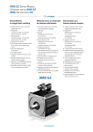
1
Axis switch
POSISwitch® AX 5000
Operating Instructions
COMMISSIONING
CONNECTION
POSIDRIVE® MDS 5000
POSIDYN® SDS 5000
MOUNTING
V 5.6
05/2011
EN
i
Table of Contents
POSISwitch® AX 5000
STÖBER ANTRIEBSTECHNIK
www.stoeber.de
Table of Contents
1. Notes on Safety ………………………………. 1
1.1
Software …………………………………………………. 9
1.2
Presentation of notes on safety ……………………….. 11
2. Technical Data …….….……………………….. 13
2.1
Electrical Data ……..……………………………………. 13
2.2
Mechanical …..…………………………………………… 16
3. Mechanical Installation ………………………. 17
3.1
Installation Location …………………………………….. 17
3.2
Mounting ……………………………………………….… 18
ID 441689.01
Table of Contents
i
POSISwitch® AX 5000
STÖBER ANTRIEBSTECHNIK
4. Electrical Installation ………………………… 19
4.1
EMV ……………………………………………………… 19
4.2
Connection ……………………………………………… 20
4.2.1 POSISwitch® AX 5000 to MDS 5000 ……………….... 20
www.stoeber.de
4.2.2 POSISwitch® AX 5000 to Encoder ……………………. 21
4.2.3 Temp. Sensors and Braking Contacts …..…………… 21
4.2.4 Power and Relays / Contactors ………..……………… 21
4.2.5 Motors ……………………………………………………. 22
5. Connection Allocation ………………………. 23
5.1
Terminal Overview ……………………………………… 23
5.2
Terminal Allocation ……………………………………... 24
6. Configuration ………………………………….. 29
7. Principal Circuit Diagram …………………… 33
8. Accessories ……………………………………. 36
ID 441689.01
i
Table of Contents
POSISwitch® AX 5000
STÖBER ANTRIEBSTECHNIK
www.stoeber.de
- This page was purposely left blank -
ID 441689.01
Notes on Safety
01
POSISwitch® AX 5000
STÖBER ANTRIEBSTECHNIK
1
Notes on Safety
Component part of the product
The technical documentation is a component part of a product.
• Since the technical documentation contains important
information, always keep it handy in the vicinity of the device
until the machine is disposed of.
• If the product is sold, disposed of, or rented out, always include
the technical documentation with the product.
ID 441689.01
www.stoeber.de
When in operation, inverters from STÖBER ANTRIEBSTECHNIK
GmbH + Co. KG may have energized or rotating parts depending
on their protection rating. Surfaces may heat up. For these
reasons, comply with the following:
• The safety notes listed in the following sections and points
• The technical rules and regulations
In addition, always read the mounting instructions and the short
commissioning instructions.
STÖBER ANTRIEBSTECHNIK GmbH + Co. KG accepts no liability
for damages caused by non-adherence to the instructions or
applicable regulations. Subject to technical changes to improve the
devices without prior notice.
This documentation is purely a product description. It does not
represent promised properties in the sense of warranty law.
1
01
Notes on Safety
POSISwitch® AX 5000
STÖBER ANTRIEBSTECHNIK
www.stoeber.de
Operation in accordance with its intended use
2
In the sense of DIN EN 50178 (previously VDE 0160), the
POSIDRIVE® FDS 5000 and MDS 5000 and the POSIDYN®
SDS 5000 model series represent the electrical equipment of
power electronics for the control of power flow in high-voltage
current systems. They are designed exclusively to power:
• Servo motors (MDS 5000, SDS 5000)
• Asynchronous motors (FDS 5000, MDS 5000 and SDS 5000)
Operation for purposes other than the intended use include the
connection of other electrical loads!
Before the manufacturer is allowed to put a machine on the
market, he must have a danger analysis prepared as per machine
guideline 98/37/EG. This analysis establishes the dangers
connected with the use of the machine. The danger analysis is a
multi-stage, iterative process. Since this documentation cannot
begin to provide sufficient insight into the machine guidelines,
please carefully study the latest standards and legal situation
yourself. After the drive controller has been installed in machines, it
cannot be commissioned until it has been determined that the
machine complies with the regulations of EG guideline 98/37/EG.
Ambient conditions
Model series POSIDRIVE® FDS 5000 and MDS 5000 and
POSIDYN® SDS 5000 are products of the restricted sales class as
described in IEC 61800-3. This product may cause high-frequency
interference in residential zones and the user may be asked to take
suitable measures.
ID 441669.01
Notes on Safety
01
POSISwitch® AX 5000
STÖBER ANTRIEBSTECHNIK
MDS 5000
SDS 5000
BG 2
5000 A
BG 3
10000 A
www.stoeber.de
The inverters are not designed for use in public low-voltage
networks which power residential areas. High-frequency
interference must be expected when the inverters are used in such
a network.
The inverters are only intended for use in TN networks.
The inverters are only designed for use on supply current networks
which can delivery at the most a maximum of symmetrical rated
short circuit current at 480 Volts as per the following table:
Max. symmetrical rated short
Device family
Size
circuit current
FDS 5000,
BG 0 and
MDS 5000,
5000 A
BG 1
SDS 5000
Install the inverter in a switching cabinet in which the permissible
maximum surrounding air temperature is not exceeded (see
mounting instructions).
The following applications are prohibited:
• Use in potentially explosive areas
• Use in environments with harmful substances as per EN 60721
(e.g., oils, acids, gases, fumes, powders, irradiation)
• Use with mechanical vibration and impact stresses which
exceed the information in the technical data of the mounting
instructions
ID 441689.01
3
01
Notes on Safety
POSISwitch® AX 5000
STÖBER ANTRIEBSTECHNIK
Implementation of the following applications is only permitted
when STÖBER ANTRIEBSTECHNIK GmbH + Co. KG has been
contacted first for permission:
• Use in non-stationary applications
www.stoeber.de
Qualified personnel
4
Since the drive controllers of the model series
POSIDRIVE® FDS 5000, POSIDRIVE® MDS 5000 and
POSIDYN® SDS 5000 may harbor residual risks, all configuration,
transportation, installation and commissioning tasks including
operation and disposal may only be performed by trained
personnel who are aware of the possible risks.
Personnel must have the qualifications required for the job. The
following table lists examples of occupational qualifications for the
jobs:
Activity
Possible occupational
qualifications
Transportation and storage
Worker skilled in storage logistics
or comparable training
Configuration
• Graduate engineer (electrotechnology or electrical power
technology)
• Technician (m/f) (electrotechnology)
Installation and connection
Electronics technician (m/f)
ID 441669.01
Notes on Safety
01
POSISwitch® AX 5000
STÖBER ANTRIEBSTECHNIK
Programming
Operation
Disposal
Technician (m/f) (electrotechnology)
• Master electro technician (m/f)
Graduate engineer (electrotechnology or electrical power
technology)
• Technician (m/f) (electrotechnology)
• Master electro technician (m/f)
Electronics technician (m/f)
•
In addition, the valid regulations, the legal requirements, the
reference books, this technical documentation and, in particular,
the safety information contained therein must be carefully:
• read
• understood and
• complied with.
Transportation and storage
Immediately upon receipt, examine the delivery for any
transportation damages. Immediately inform the transportation
company of any damages. If damages are found, do not
commission the product.
If the device is not to be installed immediately, store it in a dry,
dust-free room. Please see the mounting instructions for how to
commission an inverter after it has been in storage for a year or
longer.
ID 441689.01
www.stoeber.de
Commissioning (of a standard
application)
5
01
Notes on Safety
POSISwitch® AX 5000
STÖBER ANTRIEBSTECHNIK
www.stoeber.de
Installation and connection
6
Installation and connection work are only permitted after the device
has been isolated from the power!
The accessory installation instructions allow the following actions
during the installation of accessories:
• The housing of the MDS 5000, SDS 5000 and FDS 5000 in the
upper slot can be opened.
• The housing of the MDS 5000 and SDS 5000 in the bottom slot
can be opened.
Opening the housing in another place or for other purposes is not
permitted.
Use only copper lines. For the line cross sections to be used, see
table 310-16 of the NEC standard for 60 oC or 75 oC.
Protect the device from falling parts (pieces of wire, leads, metal
parts, and so on) during installation or other tasks in the switching
cabinet. Parts with conductive properties inside the inverter can
cause short circuits or device failure.
The motor must have an integrated temperature monitor with basic
isolation in accordance with EN 61800-5-1 or external motor
overload protection must be used.
The permissible protection class is protective ground. Operation is
not permitted unless the protective conductor is connected in
accordance with the regulations.
Comply with the applicable instructions for installation and
commissioning of motor and brakes.
ID 441669.01
Notes on Safety
01
POSISwitch® AX 5000
STÖBER ANTRIEBSTECHNIK
Commissioning, operation and service
www.stoeber.de
Remove additional coverings before commissioning so that the
device cannot overheat. During installation, provide the free
spaces specified in the mounting instructions to prevent the
inverter from overheating.
The housing of the drive controller must be closed before you turn
on the supply voltage. When the supply voltage is on, dangerous
voltages can be present on the connection terminals and the
cables and motor terminals connected to them. Remember that the
device is not necessarily de-energized after all indicators have
gone off.
When network voltage is applied, the following are prohibited:
• Opening the housing
• Connecting or disconnecting the connection terminals
• Installing accessories
Proceed as shown below to perform these tasks:
1. Disable the enable (X1).
2. Turn off the supply voltage (power pack and controller
power supply as well as any auxiliary voltages for
encoder, brake, etc.).
3. Protect the supply voltages from being turned on again.
4. Wait 5 minutes (time the DC link capacitors need to
discharge).
5. Determine isolation from the voltage.
6. Short circuit the network input and ground it.
7. Cover the adjacent, voltage-carrying parts.
ID 441689.01
7
01
Notes on Safety
POSISwitch® AX 5000
www.stoeber.de
STÖBER ANTRIEBSTECHNIK
8
You can then start your work on the drive controller.
Repairs may only be performed by STÖBER ANTRIEBSTECHNIK
GmbH + Co. KG.
Send defective devices together with a fault description to:
STÖBER ANTRIEBSTECHNIK GmbH + Co. KG
Abteilung VS-EL
Kieselbronner Str. 12
75177 Pforzheim
GERMANY
Disposal
Please comply with the latest national and regional regulations!
Dispose of the individual parts separately depending on their
nature and currently valid regulations such as, for example:
• Electronic scrap (PCBs)
• Plastic
• Sheet metal
• Copper
• Aluminum
Residual dangers
The connected motor can be damaged with certain settings of
drive controllers.
• Longer operation against an applied motor halting brake
• Longer operation of self-cooled motors at slow speeds
Drives can reach dangerous excess speeds (e.g., setting of high
output frequencies for motors and motor settings which are
unsuitable for this). Secure the drive accordingly.
ID 441669.01
Notes on Safety
01
POSISwitch® AX 5000
STÖBER ANTRIEBSTECHNIK
1.1
Software
Using the POSITool software
www.stoeber.de
The POSITool software package can be used to select the
application and adjust the parameters and signal monitoring of the
5th generation of STÖBER inverters. The functionality is specified
by selecting an application and transmitting these data to an
inverter.
The program is the property of STÖBER ANTRIEBSTECHNIK
GmbH + Co. KG and is copyrighted. The program is licensed for
the user.
The software is only provided in machine-readable form.
STÖBER ANTRIEBSTECHNIK GmbH + Co. KG gives the
customer a non-exclusive right to use the program (license)
provided it has been legitimately obtained.
The customer is authorized to use the program for the above
activities and functions and to make copies of the program,
including a backup copy for support of this use, and to install same.
The conditions of this license apply to each copy. The customer
promises to affix the copyright notation to each copy of the
program and all other property notations.
The customer is not authorized to use, copy, change or pass
on/transmit the program for purposes other than those in these
regulations. The customer is also not authorized to convert the
program (i.e., reverse assembly, reverse compilation) or to compile
it in any other way. The customer is also not authorized to issue
sublicenses for the program, or to rent or lease it out.
ID 441689.01
9
01
Notes on Safety
POSISwitch® AX 5000
STÖBER ANTRIEBSTECHNIK
www.stoeber.de
Product maintenance
10
The obligation to maintain refers to the two latest program versions
created by STÖBER ANTRIEBSTECHNIK GmbH + Co. KG and
approved for use.
STÖBER ANTRIEBSTECHNIK GmbH + Co. KG will either correct
program errors or will provide the customer with a new program
version. This choice will be made by STÖBER ANTRIEBSTECHNIK GmbH + Co. KG. If, in individual cases, the error cannot
be immediately corrected, STÖBER ANTRIEBSTECHNIK GmbH +
Co. KG will provide an intermediate solution which may require the
customer to comply with special operation regulations.
A claim to error correction only exists when the reported errors are
reproducible or can be indicated with machine-generated outputs.
Errors must be reported in a reconstructable form and provide
information which is useful to error correction.
The obligation to correct errors ceases to exist for such programs
which the customer changes or edits in any way unless the
customer can prove that such action is not the cause of the
reported error.
STÖBER ANTRIEBSTECHNIK GmbH + Co. KG will keep the
respective valid program versions in an especially safe place
(fireproof data safe, bank deposit box).
ID 441669.01
Notes on Safety
01
POSISwitch® AX 5000
STÖBER ANTRIEBSTECHNIK
1.2
Presentation of notes on safety
Notice
means that property damage may occur if the
stated precautionary measures are not taken.
CAUTION
Caution
with warning triangle means that minor injury
may occur if the stated precautionary
measures are not taken.
WARNING
Warning
means that there may be a serious danger of
death if the stated precautionary measures
are not taken.
DANGER
Danger
means that serious danger of death exists if
the stated precautionary measures are not
taken.
ID 441689.01
www.stoeber.de
NOTICE
11
01
Notes on Safety
POSISwitch® AX 5000
www.stoeber.de
STÖBER ANTRIEBSTECHNIK
12
Information
indicates important information about the
product or a highlighted portion of the
documentation which requires special
attention.
ID 441669.01
Technical Data
02
POSISwitch® AX 5000
STÖBER ANTRIEBSTECHNIK
2
Technical Data
POSISwitch® AX 5000
Designation
5th Generation
2.1 Electrical Data
General data
ID no.
Voltage
IE
without encoder and
contactor
with encoder,
without contactor
49578
24 V +20% / -15% (protected against
polarity reversal)
<100 mA
<1A
Ambient temperature
0 – 45°C
Gebersystem
EnDat®
ID 441689.01
www.stoeber.de
Model key
13
02
Technical Data
POSISwitch® AX 5000
STÖBER ANTRIEBSTECHNIK
www.stoeber.de
EnDat® Port
14
Input level
TIA/EIA 422
Connection, encoder input
Sub D 15-pole (STÖBER contact
allocation)
SUB D 15-pole (STÖBER
Connection, encoder output contact allocation – see
connection cable in chap. 8)
Output level
TIA/EIA 422
EnDat® version
EnDat® 2.1, EnDat® 2.2
Max. clock pulse frequency
2 MHz
Switchover time
< 200 µs
Galvanic isolation EnDat®
input to EnDat® input
No
Galvanic isolation
500 V
EnDat® input to 24 V supply
Max. cable length between
®
POSISwitch and inverter
80 m1
Max. cable length between
POSISwitch® and encoder
20 m1
Voltage for encoder
5.25 V
Imax for encoder
200 mA
1
Only valid in connection with STÖBER cables.
ID 441689.01
Technical Data
02
POSISwitch® AX 5000
STÖBER ANTRIEBSTECHNIK
Number of protective
connections
4
Max. output current
200 mA
Output voltage
min. 22 V at 200 mA
Connection
Screw-type terminal (max. 1.5 mm²)
Galvanic isolation to
EnDat ®
Yes
ID 441689.01
www.stoeber.de
Power protection
15
02
Technical Data
POSISwitch® AX 5000
STÖBER ANTRIEBSTECHNIK
2.2 Mechanical
Specifications in mm
16
35
Ø6
159
10
45
179
www.stoeber.de
70
6
ID 441689.01
Mechanical Installation
03
POSISwitch® AX 5000
STÖBER ANTRIEBSTECHNIK
Mechanical Installation
This chapter gives you complete information on the subject of
mechanical installation. Only specialized personnel qualified for
this task may install, commission and control the device.
3.1
•
•
•
•
•
•
•
Installation Location
Operate only in closed switching cabinet.
Avoid installation above heat-generating devices.
Ensure sufficient air circulation in the switching cabinet.
(The installation site of POSISwitch® AX 5000 may not hinder
the air circulation of the inverter.)
The installation site must be free of dust, corrosive fumes and
all liquids (in accordance with soil degree 2 as per EN 50178).
Avoid humidity.
Avoid condensation (e.g., due to anti-condensation heaters).
To satisfy EMC requirements, use mounting plates with
conductive surfaces (e.g., unpainted).
ID 441689.01
www.stoeber.de
3
17
03
Mechanical Installation
POSISwitch® AX 5000
STÖBER ANTRIEBSTECHNIK
3.2
Drilling jig
Mounting
Possible arrangement
18
~
~
I/O
Encoder 1 ... 4
~
~
~
~
POSISwitch® connection cable
Length: 500 mm (Id. No. 45405)
Length: 2500 mm (Id. No. 45386)
Encoder 1 ... 4
max. 80 m1
I/O
Umrichter
~
~
ESC
Umrichter
ESC
159 mm
www.stoeber.de
ca. 15-20 mm
1
Valid only in connection with STÖBER cables.
ID 441689.01
Electrical Installation
04
POSISwitch® AX 5000
STÖBER ANTRIEBSTECHNIK
Electrical Installation
This chapter gives you complete information on the subject of
electrical installation.
Only specialized personnel qualified for this task may install,
commission and control the device.
4.1
EMV
www.stoeber.de
4
This chapter gives you general information on EMC-suitable
installation. These are only recommendations. Depending on the
application, the ambient conditions and the legal requirements,
measures in addition to the following recommendations may be
necessary.
• Mount device on conductive surface (unpainted).
• Motor cables must be installed in separate space from the
encoder cables.
• Use only shielded cables for motor and encoder lines
(corresponding cabels can be ordered from STÖBER
ANTRIEBSTECHNIK.).
• Apply shield of the motor cable on both sides.
• The circuit breakers may not interrupt the shield lines.
• Output derating must be used for motor lines > 50 m.
• When an additional transmission plug connector is installed in
the motor cable, the shield may not be interrupted and the plug
connection may not be opened when the motor is electrified.
• When the braking line is installed in the motor cable, the braking
line must be shielded separately.
ID 441689.01
19
04
Electrical Installation
POSISwitch® AX 5000
www.stoeber.de
STÖBER ANTRIEBSTECHNIK
20
4.2
Connection
4.2.1
POSISwitch® AX 5000 to
MDS 5000/SDS 5000
POSISwitch® AX 5000 is controlled by POSIDRIVE® MDS 5000 or
by POSIDYN® SDS 5000. A connection via socket X4 on the
inverter to plug X500 on the AX 5000 enables the switching of the
axes. Completely prefabricated cables are available in the lengths
500 mm (ID no. 45405) and 2500 mm (ID no. 45386). Cf. chap. 8.
POSISwitch® AX 5000 is usually installed in the immediate vicinity
of the inverter (see chap. 3.1 and 3.2). However, if this is not
possible or desirable, a cable of up to 80 m1 in length can be used.
1
Only valid in connection with STÖBER cables.
ID 441689.01
Electrical Installation
04
POSISwitch® AX 5000
STÖBER ANTRIEBSTECHNIK
POSISwitch® AX 5000 to Encoder
The encoders of the individual servo motors are connected to
POSISwitch® AX 5000 with the STÖBER encoder cable. The
encoder of the first motor is connected with the socket Enc. 1. The
encoder of the second motor is connected with the socket Enc. 2
and so on.
The length of the encoder cable may not exceed 20 m1.
4.2.3
Temp. Sensors and Braking Contacts
Activation of a halting brake and the evaluation of the temperature
sensors on the motors is handled with braking module for 24 V
brake (BRM 5000 for MDS 5000, BRS 5000 for SDS 5000). The
brakes or temperature sensors (positor lines) allocated to the
motors are activated and deactivated via auxiliary contacts of the
applicable power relays/contactors. Chapter 7 contains examples
of correct wiring.
4.2.4
Power and Relays / Contactors
POSISwitch® AX 5000 is powered with 24 V via the screw-type
terminal strip X501 (terminals 1 and 2). Power consumption is a
maximum of 1 A. The power relays/contactors are controlled via
the AX 5000 on terminals X501.6 to X501.9. The contactors are
1
Only valid in connection with STÖBER cables.
ID 441689.01
www.stoeber.de
4.2.2
21
04
Electrical Installation
POSISwitch® AX 5000
STÖBER ANTRIEBSTECHNIK
powered via terminals X501.4 and X501.5. Chapter 7 contains
examples of correct wiring.
www.stoeber.de
4.2.5
22
Motors
The motors are activated and deactivated via power relays /
contactors. POSISwitch® AX 5000 controls and checks the power
relays/contactors. Chapter 7 contains examples of correct wiring.
Please adhere to the EMC recommendations.
Information
Use to switch the motor temperature sensor
relay contacts for low currents/voltages (gold
contacts).
ID 441689.01
Connection Allocation
05
POSISwitch® AX 5000
STÖBER ANTRIEBSTECHNIK
5
Connection Allocation
5.1
Terminal Overview
X500
Connection for the POSIDRIVE®
www.stoeber.de
This section explains the position, designation and allocation of the
terminals.
MDS 5000 or POSIDYN® SDS 5000
Enc. 1
Enc. 2 Connection for
Enc. 3 encoder 1 - 4
Enc. 4
LED
X501 Power & relays
ID 441689.01
23
05
Connection Allocation
POSISwitch® AX 5000
STÖBER ANTRIEBSTECHNIK
5.2
Terminal Allocation
This section presents and describes all interfaces.
www.stoeber.de
X500 – Connection for MDS 5000 or SDS 5000
24
Please note that pin 4 is jumpered internally with pin 12.
Pin1
8
1
1
15
9
Designation
Function
1
NC
Not connected
2
GND
Reference for power supply
3
NC
Not connected
4
VCC
Power supply 5 VDC
5
DATA
Differential input DATA
6
NC
Not connected
7
ERROR
Differential output ERROR
8
CLK
Differential input CLOCK
9
NC
Not connected
10
NC
Not connected
11
NC
Not connected
12
Sense
Sense connection
13
/DATA
Inverted, diff. input DATA
14
/ERROR
Inverted, diff. output ERROR
15
/CLK
Inverted, diff. input CLOCK
View of terminal / sub D
ID 441689.01
Connection Allocation
05
POSISwitch® AX 5000
STÖBER ANTRIEBSTECHNIK
POSISwitch® cable
1
1
9
9
10
10
11
11
12
12
13
13
14
14
15
15
2
2
3
3
4
5
6
7
5
6
7
8
8
POSISwitch®
X500
Umrichter
X4
X501 – voltage supply & relays
Pin1
Designation
Function
Data
+24VDC
Voltage supply —
0V
Reference
for 24 V
—
PE
Protective
conductor
—
+ Potential for powering
K+
1
Power for the
relays
View of terminal / sub D
ID 441689.01
power relays/contactors
Umin = 5 V
Umax = 30 V
www.stoeber.de
4
25
05
Connection Allocation
POSISwitch® AX 5000
STÖBER ANTRIEBSTECHNIK
www.stoeber.de
Pin1
26
Designation
Function
Data
K-
Reference
potential for
Pin 4
—
K1 OUT
Relay output
for 1st axis
K2 OUT
Relay output
nd
for 2 axis
K3 OUT
Relay output
for 3rd axis
K4 OUT
Relay output
for 4th axis
Imax (24 V) = 0.2 A,
Internal safety circuit
with free-wheeling diode
for relay coil.
LED
Designation
ON
Meaning
When the LED is on, the axis switch is supplied
with voltage.
1
When the LED is on, axis 1 is selected.*
2
When the LED is on, axis 2 is selected.*
3
When the LED is on, axis 3 is selected.*
4
When the LED is on, axis 4 is selected.*
* When the LED is on, communication is taking place with the
encoder of the axis. The relay output (X501.K1 OUT to X501.K4
OUT) becomes active when the axis is activated by axis
management (device control).
ID 441689.01
Connection Allocation
05
POSISwitch® AX 5000
STÖBER ANTRIEBSTECHNIK
Pin1
1
Designation
Function
1
NC
Not connected
2
GND
Reference
3
NC
Not connected
4
VCC
Power supply 5 VDC
Is jumpered internally with pin 12
5
DATA
Differential input DATA
6
NC
Not connected
7
NC
Not connected
8
CLK
Differential output CLOCK
9
NC
Not connected
10 NC
Not connected
11 NC
Not connected
12 Sense
Sense connection
Is jumpered internally with pin 4
13 /DATA
Inverted, diff. input DATA
14 NC
Not connected
15 /CLK
Inverted, diff. output CLOCK
View of terminal / sub D
ID 441689.01
www.stoeber.de
Enc. 1; Enc. 2; Enc 3; Enc. 4 – Connection for encoders 1 - 4
27
05
Connection Allocation
POSISwitch® AX 5000
STÖBER ANTRIEBSTECHNIK
Connection of the encoder to POSI Switch® AX 5000
1
9
2
www.stoeber.de
10
28
*
3
11
4
12
1
2
rs
rs
5
8
12
11
4
*
13
10
3
2
9
7
6
5
6
14
7
15
*
8
Terminal, enc. 1 to 4
on POSISwitch®
Signal
Encoder connection
Bracket flange socket
motor
Clock+ Sense DATA- DATA+ Clock- UB+ DGND
Enc. 1-4
8
12
13
5
15
4
2
Motor1
1
2
5
6
8
12
10
Cable²
Yellow
pink
brown
white
green
red
blue
1) PIN number of 12-pin encoder plug for STÖBER ED/EK motor
2) Color when STÖBER encoder cable is used
* Cables twisted in pairs.
ID 441689.01
Configuration
06
POSISwitch® AX 5000
STÖBER ANTRIEBSTECHNIK
6
Configuration
www.stoeber.de
This chapter describes the configuration of POSISwitch® AX 5000.
The user decides whether POSISwitch® will be used in the
configuration assistants during the step “inverter selection”. An
appropriate selection is offered here (see figure).
For further information on the functionality (e.g., encoder simulation
and time behavior), see application manual, chap. 6 (ID 441691).
When POSISwitch® AX 5000 configured, the device is adjusted to
the application via the following parameters.
ID 441689.01
29
06
Configuration
POSISwitch® AX 5000
STÖBER ANTRIEBSTECHNIK
www.stoeber.de
Par.
30
Fieldbus
address
2A5Ah 0h
Description
F90
Release time axis-switch: Specifies
Global
the release time of the contactor used for
r=2, w=3 the axis switchover. This minimum time is
waited before the inverter lets the next
contactor be applied.
Value range in ms: 0 ... 20 ... 32767
Fieldbus: 1LSB=1ms; Type: I16; USS-Adr:
06 16 80 00 hex
2A5Bh 0h
F91
Set time axis-switch: Specifies the
Global
set time of the contactor used for the axis
r=2, w=3 switchover. This time is at least waited
before the inverter lets the axis be
electrified.
Value range in ms: 0 ... 20 ... 32767
Fieldbus: 1LSB=1ms; Type: I16; USS-Adr:
06 16 C0 00 hex
H08
Axis,
OFF
r=2, w=2
POSISwitch® encoder selector:
Available as an option, the POSISwitch®
control module permits the connection of
several motors to one inverter. In H08 it
can be set separately for each of the four
(software) axes which connection on the
2E08h 0h
ID 441689.01
Configuration
06
POSISwitch® AX 5000
STÖBER ANTRIEBSTECHNIK
Description
POSISwitch® (i.e., which motor) is
allocated to the particular axis
configuration. This routine permits two or
more applications to be run together on
separate (software) axes with a single
motor.
NOTE
Following a change in parameter H08,
correct evaluation of the electronic
nameplate is not ensured until after a
device new start.
0: Enc1;
1: Enc2;
2: Enc3;
3: Enc4;
Fieldbus: 1LSB=1; Type: U8; USS-Adr: 08
02 00 00 hex
1 Only visible when a POSISwitch® was
detected on X4.
ID 441689.01
Fieldbus
address
www.stoeber.de
Par.
31
06
Configuration
POSISwitch® AX 5000
www.stoeber.de
STÖBER ANTRIEBSTECHNIK
32
Par.
Description
H18
Global,
OFF
read (2)
POSISwitch® port-status: Indicates
as a binary word the POSISwitch® ports to
which encoders are connected. This is
determined by the inverter during startup.
Fieldbus
address
2E12h 0h
Fieldbus: 1LSB=1; Type: U8; USS-Adr: 08
04 80 00 hex
1 Only visible when a POSISwitch® was
detected on X4.
U12
480Ch 0h
Level motor connection: When the
Global
axis switch via POSISwitch® is utilized, the
r=3, w=3 inverter can test during switching whether
the contactor of the motor to be switched
off has actually broken contact (opened).
In addition, under certain circumstances, it
can be determined that no motor is
connected.
0: inactive;
3: Fault;
Fieldbus: 1LSB=1; Type: U8; USS-Adr: 15
03 00 00 hex
ID 441689.01
Principal Circuit Diagrams
07
POSISwitch® AX 5000
STÖBER ANTRIEBSTECHNIK
L1
L2
L3
PE
4
3
2
1
5
6
7
8
X10
X2
X302
X300
®
POSIDRIVE MDS 5000
K2
K1
M1
1
brake
M4
K3
K4
_
U
V
W
PE
X20
K1
K2
M1
X500
K3
K4
M3
M2
M4
15
15
15
15
Enc. 1
Enc. 2
Enc. 3
Enc. 4
®
POSISwitch AX 5000
X501
X4
1 2 3 4 5
F
ID 441689.01
K4
brake
M3
brake
M2
K2
M4
K4
K3
brake
M1
K1
M3
K3
K2
K1
X301
K4
M2
K2
K1
4
3
+
1
. 15
.
.
15
PE
24V
0V
K3
6
K1
7
K2
8
K3
9
K4
www.stoeber.de
L1
L2
L3
PE
Principal Circuit Diagrams
BRM 5000
7
33
07
Principal Circuit Diagrams
POSISwitch® AX 5000
STÖBER ANTRIEBSTECHNIK
L1
L2
L3
PE
L1
L2
L3
PE
1
2
X2
®
6
1
2
3
4
5
6
X302
X5
1
2
4
M3
M4
K1
K2
K3
K4
K1
K2
K3
K4
K2
K3
K1
K2
K3
K4
brake2
M4
brake2
M3
K3
K2
K1
K4
brake2
M2
brake2
M1
_
brake1
M4
brake1
M3
brake1
M2
K1
+
X300
K4
M2
brake1
M1
BRS 5000
1
2
3
4
5
6
POSIDYN SDS 5000
www.stoeber.de
K3
M1
X10
34
K2
K1
K4
U
V
W
PE
X20
K1
K2
M1
1
. 15
.
.
15
X500
K3
K4
M3
M2
M4
15
15
15
15
Enc. 1
Enc. 2
Enc. 3
Enc. 4
®
POSISwitch AX 5000
X501
X4
1 2 3 4 5
F
6
K1
7
K2
8
K3
9
K4
PE
24V
0V
ID 441689.01
Principal Circuit Diagrams
07
POSISwitch® AX 5000
Information
The lines to the brake and temperature
sensor must be opened with two poles when
an axis switches so that no interference is
created (e.g., with long lines).
ID 441689.01
www.stoeber.de
STÖBER ANTRIEBSTECHNIK
35
08
Accessories
POSISwitch® Ax 5000
STÖBER ANTRIEBSTECHNIK
8
Accessories
www.stoeber.de
POSISwitch® connection cable
36
ID no.
Description
45405
Connection between inverter and
POSISwitch® AX 5000,
Length: 0.5 m
45386
Connection between inverter and
POSISwitch® AX 5000,
Length: 2.5 m
ID 441689.01
Global Presence
Address registers
Always up to date on the internet: www.stoeber.de → contact
• Technical Offices (TB) for advice and marketing in Germany
• Global presence for advice and marketing in about 25 countries
• Service Network Germany
• Service Network International
• STÖBER Subsidiaries:
STÖBER ANTRIEBSTECHNIK GmbH
Fabriksplatz 1
4662 Steyrermühl
Fon +43 7613 7600-0
Fax +43 7613 7600-2525
eMail: [email protected]
www.stoeber.at
Switzerland
STÖBER SCHWEIZ AG
Rugghölzli 2
5453 Remetschwil
Fon +41 56 496 96 50
Fax +41 56 496 96 55
eMail: [email protected]
www.stoeber.ch
China
STOBER CHINA
German Centre Beijing
Unit 2010, Landmark Tower 2,
8 North Dongsanhuan Road
Chaoyang District
100004 Beijing
Fon +86 10 65907391
Fax +86 10 65907393
eMail: [email protected]
www.stoeber.cn
USA
STOBER DRIVES INC.
1781 Downing Drive
Maysville, KY 41056
Fon +1 606 7595090
Fax +1 606 7595045
eMail: [email protected]
www.stober.com
Great Britain
STOBER DRIVES LTD.
Ability House
121 Brooker Road, Waltham Abbey
Essex EN9 1JH
Fon +44 1992 709710
Fax +44 1992 714111
eMail: [email protected]
www.stober.co.uk
Japan
STOBER Japan
P.O. Box 113-002, 6 chome
15-8, Hon-komagome
Bunkyo-ku
Tokyo
Fon +81 3 5395-6788
Fax +81 3 5395-6799
eMail: [email protected]
www.stober.co.jp
France
STÖBER S.a.r.l.
131, Chemin du Bac à Traille
Les Portes du Rhône
69300 Caluire et Cuire
Fon +33 4 78989180
Fax +33 4 78985901
eMail: [email protected]
www.stober.fr
Italy
STÖBER TRASMISSIONI S. r. l.
Via Risorgimento, 8
20017 Mazzo di Rho (Milano)
Fon +39 02 93909-570
Fax +39 02 93909-325
eMail: [email protected]
www.stoeber.it
www.stoeber.de
Austria
m
STÖBER ANTRIEBSTECHNIK GmbH + Co. KG
Kieselbronner Str. 12
75177 PFORZHEIM
GERMANY
Tel. +49 (0)7231 582-0
Fax. +49 (7231) 582-1000
E-Mail: [email protected]
24/h service hotline +49(0) 180 5 786 323
www.stober.com
Technische Änderungen vorbehalten
Errors and changes excepted
ID 441689.01
05/2011