1
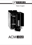
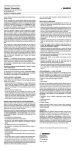
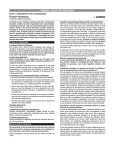
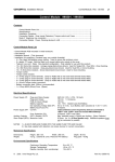
Operating Instructions
Braking Chopper BC 200
Berges electronic • D–51709 Marienheide-Rodt • Tel. 02264/17-0 • Fax 02264/17126
Contents
Page
1
2
04.10.00
BC_200_G
Installation and Operating Instructions for the Braking Chopper BC 200 . . . . . . . . . . . . . 2
1.1
Introduction . . . . . . . . . . . . . . . . . . . . . . . . . . . . . . . . . . . . . . . . . . . . . . . . . . . . . . . . . . 2
1.2
Type Series . . . . . . . . . . . . . . . . . . . . . . . . . . . . . . . . . . . . . . . . . . . . . . . . . . . . . . . . . . 2
1.3
Technical Data . . . . . . . . . . . . . . . . . . . . . . . . . . . . . . . . . . . . . . . . . . . . . . . . . . . . . . . 2
1.4
Description of the Maximum Duty Cycle . . . . . . . . . . . . . . . . . . . . . . . . . . . . . . . . . . . 3
1.5
Determining the Braking Time with 20 Ω Braking Resistor and 5.5 kW Drive Power . . 4
1.6
Determining the Braking Time with 20 Ω Braking Resistor and 7.5 kW Drive Power . . 5
1.7
Determining the Braking Time with 20 Ω Braking Resistor and 11 kW Drive Power . . 5
1.8
Determining the Braking Time with 20 Ω Braking Resistor and 15 kW Drive Power . . 6
1.9
Determining the Braking Time with 20 Ω Braking Resistor and 22 kW Drive Power . . 6
Installation and Wiring . . . . . . . . . . . . . . . . . . . . . . . . . . . . . . . . . . . . . . . . . . . . . . . . . . . . . . 7
2.1
Housing Drawing, Braking Resistor RBKK20 (IP 54) . . . . . . . . . . . . . . . . . . . . . . . . . . 7
2.2
Housing Drawing, Braking Resistor RBK20 (IP 21) . . . . . . . . . . . . . . . . . . . . . . . . . . . 7
2.3
Connection of the Braking Resistors. . . . . . . . . . . . . . . . . . . . . . . . . . . . . . . . . . . . . . . 8
2.4
Connection Terminal Assignment, Braking Chopper BC 200 . . . . . . . . . . . . . . . . . . . 11
Operating Instructions
Braking Chopper BC 200
1
Berges electronic • D–51709 Marienheide-Rodt • Tel. 02264/17-0 • Fax 02264/17126
1
Installation and Operating Instructions for the Braking Chopper BC 200
1.1
Introduction
This Manual contains instructions on installing and operating the BC 200 (Order number:
34001244; enclosure IP 21). The braking chopper is suitable for operation in conjunction
with frequency converters of Type Series ACP 6000 and UD 7000 and for universal use in
conjunction with power systems with a voltage between 380 and 460 V AC.
1.2
Type Series
The braking chopper BC 200 supplements the equipment's own braking choppers and
braking resistors.
Device assignment
(recommended)
ACP
6005-5 to 6022-0
ACP
6030-0 to 6055-0
UD
7030–7160
BC 200 (200 A)
34001244
Braking chopper
Order No.
RBKK20 – IP 54
34001161B
or
RBK20 – IP 21
34001048
BC resistor, Type
Order No.
2 × RBKK20 – IP 54
34001161B
or
2 × RBK20 – IP 21
34001048
RBKK20 – IP 54 (1)
34001161B
or
RBK20 – IP 21 (1)
34001048
NOTES:
Please use Chapters 1.5–1.9 as a configuration aid. We recommend that you contact
BERGES in the case of extreme applications.
(1)
1.3
2
RBKK20 – IP 54 or RBK20 – IP21 can be connected as required in parallel with an
overall resistance of up to 5 Ohm.
Technical Data
Continuous current
30 A
Operating voltage (range)
300 VDC–800 VDC
Response threshold
700–760 VDC
Power supply, fan
24 VDC/1 A (suitable for 2 RBKK20s – IP 54).
Ambient temperature
0–50 °C.
Enclosure
IP 21.
Signalling contact
220 VAC/0,3 A; 24 VDC/2 A.
Dimensions and weights
See the illustration below.
Installation instructions
Cable length between frequency converter and BC maximum 5 m and twisted; an additional capacitor bank
(which can retrofitted as an option) is necessary in the
case of a cable length exceeding 5 m. Cable length between BC and braking resistor maximum 5 m twisted.
Operating Instructions
Braking Chopper BC 200
04.10.00
BC_200_G
Berges electronic • D–51709 Marienheide-Rodt • Tel. 02264/17-0 • Fax 02264/17126
140
129
153
5
220
188
∅ 5.5
∅ 29
5
∅ 22
119
41
47
1.4
Weight: 3.3 kg
Description of the Maximum Duty Cycle (1)
If the energy to be braked is greater than the braking resistor can absorb, the maximum permitted temperature will be exceeded. This is followed by the cooling phase. This On/Off ratio is shown in the sketch below:
Maximum duty cycle
T1
T2
Braking time (min.) = T1
Overall cycle time (min.) = T2
(1) Only IP 54 braking resistor with separately driven fan.
04.10.00
BC_200_G
Operating Instructions
Braking Chopper BC 200
3
Berges electronic • D–51709 Marienheide-Rodt • Tel. 02264/17-0 • Fax 02264/17126
The following formula can be used in order to ensure that the temperature limits are not
reached:
Braking time (min.) T1
Duty cycle in percent = ------------------------------------------------------------------------- × 100%
Overall cycle time (min.) T2
The value thus calculated must be less than the maximum duty cycle value.
If the specified data of the maximum duty cycle or of the maximum braking time of a braking
chopper unit does not suffice, it is possible to connect two units in parallel (only with works
approval).
The diagrams on the pages which follow show the temperature development of the individual braking chopper power categories.
NOTE:
Using the IP 21 braking resistors without separate cooling results in approx. 30% braking
power of the IP 54 version.
1.5
Determining the Braking Time with 20 Ω Braking Resistor and 5.5 kW Drive
Power
60
50
40
°C 30
20
10
0
0
5
10
15
20
25
30
min
4
Operating Instructions
Braking Chopper BC 200
04.10.00
BC_200_G
Berges electronic • D–51709 Marienheide-Rodt • Tel. 02264/17-0 • Fax 02264/17126
1.6
Determining the Braking Time with 20 Ω Braking Resistor and 7.5 kW Drive
Power
70
60
50
40
°C
30
20
10
0
0
5
10
15
20
25
30
min
1.7
Determining the Braking Time with 20 Ω Braking Resistor and 11 kW Drive
Power
70
60
50
°C
40
30
20
τ on
10
τ off
0
0 1 2 3 4
5 6 7 8 9 10 11 12 13 14 15 16 17 18 19 20
τ on = 4.5 min.
04.10.00
BC_200_G
min
τ off = 5.6 min.
Operating Instructions
Braking Chopper BC 200
5
Berges electronic • D–51709 Marienheide-Rodt • Tel. 02264/17-0 • Fax 02264/17126
1.8
Determining the Braking Time with 20 Ω Braking Resistor and 15 kW Drive
Power
70
60
50
°C
40
30
20
τ on
10
τ off
0
0 1 2 3 4 5 6 7 8 9 10 11 12 13 14 15 16 17 18 19 20 21 22
τ on = 3.4 min.
1.9
min
τ off = 5.6 min.
Determining the Braking Time with 20 Ω Braking Resistor and 22 kW Drive
Power
80
70
60
50
°C 40
30
20
10
τ on
τ off
0
0 1 2 3 4 5 6 7 8 9 10 11 12 13 14 15 16 17 18 19 20 21 22
τ on = 2.5 min.
6
min
τ off = 5.6 min.
Operating Instructions
Braking Chopper BC 200
04.10.00
BC_200_G
Berges electronic • D–51709 Marienheide-Rodt • Tel. 02264/17-0 • Fax 02264/17126
2
Installation and Wiring
2.1
Housing Drawing, Braking Resistor RBKK20 (IP 54)
Braking resistor RBKK20 – IP 54 (Order No.: 34001161B)
2.2
Housing Drawing, Braking Resistor RBK20 (IP 21)
Braking resistor RBK20 – IP 21 (Order No.: 34001048)
04.10.00
BC_200_G
Operating Instructions
Braking Chopper BC 200
7
Berges electronic • D–51709 Marienheide-Rodt • Tel. 02264/17-0 • Fax 02264/17126
2.3
Connection of the Braking Resistors
Wiring with braking resistor RBK20
ATTENTION!
8
Wire the connection terminals for the thermal protection (Clixon) so that the mains
voltage is disconnected if the braking resistor overheats.
Operating Instructions
Braking Chopper BC 200
04.10.00
BC_200_G
Berges electronic • D–51709 Marienheide-Rodt • Tel. 02264/17-0 • Fax 02264/17126
Wiring with braking resistor RBKK20
ATTENTION!
04.10.00
BC_200_G
Wire the connection terminals for thermal protection (NTC) to the BC 200 so that the
mains voltage is disconnected in the event of overheating of the braking resistor
(use the signalling contact of the BC 200 for this).
Operating Instructions
Braking Chopper BC 200
9
Berges electronic • D–51709 Marienheide-Rodt • Tel. 02264/17-0 • Fax 02264/17126
Wiring with 2 braking resistors RBKK20 in a parallel circuit
ATTENTION!
Wire the connection terminals for thermal protection (NTC) to the BC 200 so that the
mains voltage is disconnected in the event of overheating of the braking resistor
(use the signalling contact of the BC 200 for this).
NOTES:
10
•
Depending on requirements, up to 4 braking resistors, each 20 Ω, can be operated in
parallel with the BC 200. Monitoring with 2 NTC resistors is adequate. A BC 200 can
power up to 2 fan pairs with a supply voltage of 24 VDC. An external power supply of 24
VDC may be necessary.
•
Note the external fusing. If external fusing is required, please use the following fuses:
Bussmann, mounting size equivalent to Neozed D01, E14.
IP 54 fuse holders from Bussmann, Type: HEY-JJ-DLRC-J (available from BERGES).
•
The connecting cable between inverter +/- and braking chopper may not exceed
a length of 5 m. The cable must also be twisted.
Operating Instructions
Braking Chopper BC 200
04.10.00
BC_200_G
Berges electronic • D–51709 Marienheide-Rodt • Tel. 02264/17-0 • Fax 02264/17126
2.4
Connection Terminal Assignment, Braking Chopper BC 200
PL1
PL2
A B C D
S3
OFF
A B
S1
PL3
OFF
BC_200_G
Operating Instructions
Braking Chopper BC 200
GND
NTC2 (10 kOhm)
NTC1 (10 kOhm)
Lü−
Lü+
Fan (−)
Fan (+)
Signalling contact
−BR
+BR
+ZK
−ZK
04.10.00
MK
Control terminals
MK
Power terminals
11
Berges electronic • D–51709 Marienheide-Rodt • Tel. 02264/17-0 • Fax 02264/17126
•
Adjustable electrical brake protection with switch S3:
S3A ON:
S3B ON:
S3D ON:
All switches OFF:
Minimum protection.
Slightly higher protection.
High protection.
No protection (maximum braking power; FACTORY DEFAULT
SETTING).
Maximum protection (minimum braking power).
All switches ON:
•
NTC inputs
(NTCs with the following characteristics should be connected):
25 °C .... 10k.
30 °C .... 7k8 Fan off.
35 °C .... 6k4 Fan on.
58 °C .... 2k4 Increased temperature.
65 °C .... 1k8 Overtemperature signalling ON.
58 °C .... 2k5Overtemperature signalling OFF.
NOTE:
If one of the two inputs is not used, a resistor with a rating of approx. 10 kΩ must be
connected! The inputs may not remain disconnected!
•
Operating state indicators:
POWER (PL1):
DC link voltage applied.
BRAKE (PL2):
Brake active.
WARNING (PL3): Signalling contact open (possible causes):
– Increased temperature of the braking resistor;
braking still possible.
– Overtemperature; braking no longer possible.
– Electrical brake protection active; braking no longer possible.
•
Terminal designations:
+ZK:
–ZK:
+BR:
–BR:
MK:
Lü–:
Lü+:
NTC1, NTC2:
GND
•
DC link voltage (from inverter), positive terminal.
DC link voltage (from inverter), negative terminal.
Braking resistor, positive.
Braking resistor, negative.
Signalling contact.
Fan GND.
Fan 24 V/1 A.
NTC terminals, each 10 kOhm (e.g. Siemens B57045).
Permanently adjustable values of the brake cut-in voltage UZK with switch S1:
S1A S1B
UZK
OFF OFF 760 V (1)
ON OFF
730 V
OFF ON
700 V
ON ON
700 V
(1) FACTORY DEFAULT SETTING.
12
Operating Instructions
Braking Chopper BC 200
04.10.00
BC_200_G
BERGES electronic GmbH
Industriestraße 13 • D–51709 Marienheide-Rodt
Postfach 1140 • D–51703 Marienheide
Tel. (0 22 64) 17-0 • Fax (0 22 64) 1 71 26