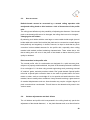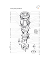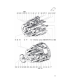
1
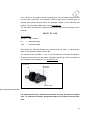
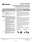
Operating Instructions
for Rolling Heads type:
RR 22-2
Instructions for rolling threads
Page
1.
The material to be rolled must be suitable for cold working.
2.
Generally, the initial diameter should coincide with the effective diameter of the thread
15
14 - 20
to be produced. Any increase to this dimension will present a risk of damage to the
thread rolls.
3.
All parts must be chamfered prior to rolling. The recommended angle for vee threads is
18
15° (30° included) to a depth of between 0.016" and 0.032" (0.4 mm to 0.8 mm) below
the minor diameter. For Acme threads the angle should be approximately 8° (16° incl.).
4.
When any alteration is made to the setting of the head, such as adjustment or the
13
fitting of new dies, the next component produced should be carefully checked. It is
frequently advisable to roll a test piece before proceeding with a large production run.
5.
The rolling speed must not be less than 100 feet per min. (30 m/min)
6.
The coolant should be a rich mixture of cutting oil and must be applied generously to
18 – 22
21
the point of engagement between rolling dies and workpiece. During rolling, the
component should become moderately warm at most. The coolant should be well
filtered to avoid contamination from ships or abrasive particles.
7.
Threads must always be rolled in one pass. Due to the work hardening action, a
22, 28
second pass involves a risk of damage to the dies.
8.
All rolls and holders are manufactured as sets and must only be used as such. To
8, 8
assist identification, each individual set is marked with a set number. For right hand
threads, both holders and rolls should be placed in the head with their position
numbers running clockwise in the correct order:
1 – 2 – 3. For left hand threads, special L. H. holders must be used but the same rolls
are applied. The difference being that the position numbers of the rolls should then be
placed anti-clockwise in the correct order.
9.
Unless otherwise stated, WAGNER® thread rolls may be reversed in sets for longer
10, 11
life. The reverse marking A – B – C is then applicable, clockwise and in correct
alphabetical sequence.
10.
Clamp the workpiece concentrically. To start the rolling action, present the work to the
29
head briefly but firmly. Swift and positive engagement should follow.
11.
Careful setting of stops will avoid collision damage and provide the desired thread run-
33
out when threading up to a shoulder, flange etc.
12.
The thread rolling operation will not eliminate such defects as irregular material, lack of
28
elongation properties, decarbonised areas in forged or rolled blanks or defective
seams in welded tube.
See chapter 6: Consequences of improper setting and use of the threads.
25 - 33
2
Table of Contents
1.
Uses – operating range – advantages
5
2.
Changing the roll holders
7
2.1.
Installing the roll holders
8
2.2.
Roll holder tables and roll holder coding
8
3.
Changing profile rolls
10
3.1.
Profile roll coding
11
4.
Adjusting the diameter
13
5.
Rolling the threads
14
5.1.
Operating procedure and condition of the blank
14
5.1.1. Cold work characteristics of the material
5.1.2. Preparing the blank
5.1.3. Chamfering the part
15
16
18
5.2.
18
Machine requirements
5.2.1. Rolling speed and required power
5.2.2. Cooling the rolling head
19
21
5.3.
5.4.
How to correct
Various adjustments and their effects
22
22
5.5.
Rolling die life in terms of production
23
6.
Consequences of improper setting and use of RR 22-2
25
6.1.
Imperfect threads
28
7.
Method of operation for rotating rolling heads type RR 22
32
8.
Operation and use of the thread rolling head
33
8.1.
Operation
33
8.2.
Use
8.2.1. Adjusting the rolling head
35
35
8.2.2. Adjusting the thread length
8.2.3. Dismantling and assembling the rolling head
35
36
9.
Spare parts list Rotating Rolling Head, type RR 22-2
39
10.
Roll Holder Table RA 22
43
3
The part numbers mentioned in the text are shown in the drawings of each rolling
head on pages 39 to 40.
These part numbers should be indicated in orders for spare parts.
The dimensions of the rolling heads, the mounting dimensions as well as the
opening and closing strokes and their directions are listed in the respective
specifications contained in the thread rolling head brochure.
With the WAGNER® thread rolling head, you have acquired a heavy-duty
tool workmanship and top grade materials (casehardened and ground steel)
designed for use at very high operating speeds. Sturdy construction, ensure long and dependable operation.
However, where the rolling head is exposed to dirt, swarf or ships, the
following safeguards should be provided:
•
efficient cleaning (filtering) of the coolant.
•
suitable protection against dirt and chips.
•
regular cleaning and servicing of the rolling head.
This will ensure dependable operation and minimise wear.
4
1.
Uses – operating range – advantages
Threads of different pitch and different diameter can be rolled in one head simply
by changing the roll holders.
Equipped with three equi-spaced, idling profile rolls, the thread rolling head
produces external threads in one pass by cold work.
WAGNER® thread rolling heads are suitable for rolling:
All cylindrical external threads such as vee-threads (to metric, British or US
standards), Acme threads, round threads, wood screw threads as shown in the
operating range specifications and tool list (holder table), using materials that are
suitable for cold work and have been prepared as required. The regular tools are
for single right-hand threads. Double threads and threads with higher pitches than
indicated in the normal operating range specifications are only available as
special versions upon request. Triple and multiple threads as well as square
threads and threads having a flank angle of less than 10° cannot generally be
rolled.
Left-hand threads with roll holders for left-hand threads. Sense of rotation of the
part opposite to that for right-hand threads. Profile rolls and all other conditions as
for right-hand threads.
Taper threads by means of tapered profile rolls, the maximum thread length
being confined to the width of the profile roll. The normal taper is 1:16.
Tapered profile rolls can only be used on one side.
Special threads and profiles. Knurling and burnishing of shafts upon special
request. Where a section to be threaded is situated between two diameters
greater than the minor diameter of the required thread, this cannot be rolled. The
part would not be capable of entering the closed rolling dies.
Thread tolerances. The tools indicated in the roll holder tables are sure to
produce "medium" threads of or ISO – 6 g tolerance when making vee-threads.
Where the blanks answer the requirements (premachining and suitable cold work
characteristics of the material) the "fine" or ISO – 4 h thread tolerance can also be
obtained.
In the event of special requirements, please submit details for quotation. As far as
the accuracy of the thread pitch is concerned, it should be kept in mind that the
5
cold work behaviour of the material and the degree to which the thread is rolled
play a major part. The normal thread rolling dies are intended for generally used
engineering steel with normal threads for a nut height of 0.8 to 1 d. Specially
corrected tools (see chapter 5.1.1 on page 15) are needed for rolling threads
involving special requirements in regard of pitch accuracy and for materials with
special cold work characteristics.
Thread rolling offers many advantages. Since the thread contour is formed by
cold work, the grain structure remains unbroken, and the useful cross-section is
not reduced by notching. The fatigue strength is improved. The resulting work
hardening of the material improves the resistance to wear and corrosion. In this
way, the surface hardness of the thread flank can be increased by 1½ to 2 times,
depending upon the material involved. The surface of the rolled thread is
burnished by the rolling operation so that the thread is less likely to become
seized.
Fig. 1: Grain flow of a rolled thread
6
2.
Changing the roll holders
To remove the roll holders, the scroll has to be pulled from the rolling head. For
this purpose, remove the head cap screws [305] and twist the scroll until it can be
pulled off clear of the roll holders. To twist the scroll, turn out the grub screws
[301] in the scroll as far as required.
1. Loosen for changing
1. Remove for
the roll holders.
changing the roll
2. For diametral adjust-
holders.
2. Loosen for dia-
ment: tighten for redu-
metral adjustment.
cing the diameter.
Roll holder
Loosen for reducing the
Attach clamping disc
diameter
before pulling off the
Inset
scroll.
Fig. 2: Manipulating the head and changing roll holders
When dealing with the RS 22 and RR 22 heads, the roll holders are held together
by a clamping disc [250] while pulling off the scroll. After the scroll has been
removed and with the head in the open condition, swing out the roll holders until
they are released from their bayonet mount and can be pulled out of the body.
7
2.1.
Installing the roll holders
Introduce the holder stems into the holes in the body and swing the holders
toward the centre so that the scroll can be slipped over the holders. When dealing
with the RS 22 and RR 22 heads, attach the clamping disc [250] to the holders.
For rolling right-hand threads, mount the roll holders in the order of 1, 2, 3 in
clockwise direction and for left-hand threads in the order of 1, 2, 3 in anti-clockwise direction.
Furthermore: Restore the scroll, adjust the diameter by means of the grub screws
[301], and clamp by means of the head cap screws [305] in the insets [303]/[304].
Before mounting the parts, clean them well and apply molybdenum di-sulphide to
the sliding surfaces. The thrust bushings [16] must be freely movable.
swing roll holders outward and pull out
Fig. 3: Exchanging the roll holders - holder removal (RS and RR 22 heads)
2.2.
Roll holder tables and roll holder coding
The roll holder tables indicate the threads that can be rolled with the various roll
holder sizes as well as the associated size of the profile rolls. The profile rolls are
8
to be chosen in accordance with the thread pitch. The roll holder charts include
only the most commonly used threads. Please consult us for unlisted types of
threads and special threads within the diametral ranges of the individual roll
holders. The roll holder tables can be found on page 43.
The roll holder designation is engraved into the front face of the roll holder, as for
instance
RA 22 B 3.40
This signifies:
RA 22 =
type of head
B
=
diametral range
3.40
=
roll holder angle
Roll holders for left-hand threads are provided with the letter “L” following the
letter for the diametral range such as “BL”.
The number of the roll holder, 1, 2 or 3, is found below the roll holder designation.
Engraved in the back of the roll holder, behind the profile roll, is the set number of
the roll holder, as for instance K 67 (see also Fig. 4).
Number of
set
Roll holder
designation
Holder number
Fig. 4: Roll holder identification
It is important to keep in mind that roll holders can only be used in complete
sets, i. e. both the roll holder designation and the set number must be identical.
9
3.
Changing profile rolls
The rolls must be carefully cleaned before they are installed. Apply molybdenum
di-sulphide to the hole (applying a thin coat of paste). Place the roll on a plaine
surface and introduce a mounting pin having the same diameter as the roll journal
pin and a length of slightly less than the width of the roll into the center of the roll
hole. Fill the space around the mounting pin with the specified number of needles
and bearing grease. (See also the drawings on pages 39 to 40 showing the
individual components of the thread rolling head with mounting pins [50], [51],
[52].)
Important note
Care must be taken to avoid the use of damaged needles. In the event of loss or
damage to one needle only, the whole set must be discarded. Never replace one
single needle, always a complete set.
During use, the needles are subject to considerable stress with a resulting
decrease in diameter as they wear. To put a needle of normal size in with others
that are worn would place such a strain upon it as to cause fracture and probably
the destruction of the rolls.
Needles must always be replaced in complete sets consisting of the number
specified in the tool list. Needles supplied by WAGNER® are manufactured to
extremely close tolerances. Under no circumstances should commercial needles
be used as they are outside the accuracy demanded by the thread rolling
process. The mounting pin must turn freely in the bearing needles.
With the mounting pin in position, insert the profile roll into the roll holder. By
pushing the journal pin through, from the back face (holder stem side), the
mounting pin will be ejected and the journal pin will assume its correct position.
10
The roll numbers 1 – 2 – 3 or, with reversed rolls, the letters A – B – C must be in
front and should agree with the holder numbers 1 – 2 – 3. To remove the profile
rolls, it is advisable to press out the roll journal pin by means of the mounting pin.
This facilitates the removal of the roll and prevents loss of the needles. In special
cases, the bearing needles can be replaced by carbide bearing sleeves.
3.1.
Profile roll coding
The faces of the profile rolls are coded as follows:
1.
The number of the set: this consists of a figure, a letter, and an additional
figure, for example 15 H 12.
2.
The roll number 1, 2 or 3 and, on the back, the letters A, B or C.
3.
Details concerning the type of thread and pitch plus additional numbers
and figures identifying some special feature.
4.
Additional letters are a factory coding.
The coding under items 1, 3 and 4 must agree for the rolls within one set.
Fig. 5: Thread roll identification
11
Reference Item 3: Examples for the identification of the type and thread and
thread pitch:
Coding - M 2.0 St Z:
Thread roll for all metric threads to DIN 13 (M) with a pitch of 2.0 mm (2.0 St) with
correction (Z).
Coding - M 2.0 P Z:
Thread roll for all metric threads to DIN 13 (M) with a pitch of 2.0 mm according to
ISO profile (2.0 P) with correction (Z).
Coding - W 14 GG Z:
Thread roll for all Whitworth threads with 55° flank angle to DIN 11, BSW aid BSF
as well as for Whitworth pipe threads to DIN 259 (W) with a pitch of 14 threads
per inch (14 GG) with correction (Z).
Coding - UN 14 GG Z:
Thread roll for all UN threads (UNC, NC, UNF, UNEF, NEF) to ASA Standards
(UN) with a pitch of 14 threads per inch (14 GG) with correction (Z).
Thread rolls for taper threads have an additional identification of the taper as for
instance:
Coding - W 1 GGZK 1:16:
Thread roll for Whitworth pipe threads with a pitch of 14 threads per inch and a
taper of 1 :16, with correction (Z).
Other types of threads contain the respective identification in their coding such as
Tr = trapezoidal or standard Acme screw threads,
H = wood threads, etc.
Other letters or figures following the pitch signify special features of the thread roll
as. For example, those required for correcting some special behavior of the
material or deviations from the normal thread profile etc.
12
4.
Adjusting the diameter
Adjustment of the thread rolling head for the thread diameter is preferably
accomplished by means of a sample thread.
In such case, the closed head is adjusted by means of the grub screw [301]
towards the sample thread until the latter can no longer be turned. For this
purpose, the scroll has to be loosened by turning out the three head cap screws
[305].
Begin with tightening the grub screw reducing the diameter - left-hand grub screw
in the RS 22 and RR 22 heads when looking upon the front face of the head - and
turning out the opposite grub screw. Once the correct position has been found,
turn back the reducing grub screw a little to facilitate the removal of the sample
thread.
The division on the scroll permits marking the position thus found for the scroll to
be restored to this position for movement against the right-hand grub screw.
After the three head cap screws [305] have been tightened again, a trial thread
can be rolled. Depending on the results, readjust the head by means of the grub
screw [301] after the head cap screws have been loosened. If no sample thread is
available, an arbor or pin can be used whose diameter is equal to the minor
diameter of the thread to be rolled. However, this method involves greater risks of
maladjustments and deviations.
The adjustment of the thread length varies with the type of head.
13
5.
Rolling the threads
5.1.
Operating procedure and condition of the blank
The flow of material caused by the thread rolling operation by cold work (the
volume of material displaced by the rolling dies from the peaks of the thread
profile towards the core of the threaded part must equal the volume flowing into
the peaks) calls for an initial or pre-machined diameter that is about equal to the
effecfive diameter of the thread.
Fig. 6: Initial diameter for thread rolling
In the majority of cases, when dealing with vee-threads, this diameter is at the
lower limit of the "fine" tolerance of the pitch diameter. But it can also be slightly
bigger than the effective diameter, especially where the material is allowed to flow
freely in longitudinal direction.
The difference a/2 at the initial
diameter results in b/2 at the
thread diameter.
Fig. 7: Profile displacement during the thread rolling
operation.
14
Changes in the initial diameter are multiplied in the major diameter of the rolled
thread by a factor of about 2 to 5. A change of 0.01" in the initial diameter can
thus provoke a change of 0.05" in the major diameter of the thread (see page 17).
This, practically, indicates the tolerance with which the previously found initial
diameter has to be maintained.
5.1.1. Cold work characteristics of the material
Generally speaking, all materials capable of being machined by cold work such as
pressing, upsetting, etc. and of withstanding the stresses of cold work without
destruction are also suitable for thread rolling. A yardstick for determining the
possibility of the thread rolling is the elongation and the strength or hardness of
the material, i.e. its resistance to the penetration of the rolling dies. Normal thread
rolls permit the economical rolling of threads into materials having a strength of up
to about 76 long tons square inch at an elongation of at least 10 to 12% for veethreads and of at least 12% for Acme standard screw threads and similar threads.
Special thread rolls make it possible to roll materials up to a strength of 95 to 107
tons per square inch at an elongation of as little as 7% economically. High alloy
materials of high elongation and low yield point but marked by a high degree of
work hardening are likely to restrict the use of the thread rolling method.
The following steels are suitable for thread rolling: mild steels, alloyed and nonalloyed engineering steels, high-alloy, high-temperature and stainless steels, tool
steels and high-speed steels that are not heat-treated.
Free cutting steels with over 15% sulphur or containing lead tend to spring
surface cracks under heavy cold work stresses and should, therefore, only be
used for rolling vee-threads when containing high amounts of sulphur. As far as
non-ferrous metals are concerned, MS 58 (hard drawn free cutting brass) is rarely
suitable for thread rolling purposes. Some alloys of aluminum, malleable cast iron
and plastics cannot be rolled in all instances. Grey cast iron and most injection
castings, likewise, are not suitable for thread rolling.
15
5.1.2. Preparing the blank
Determining the initial diameter:
As stated in paragraph 5.1, the initial diameter for rolling vee-threads into normal
engineering steels is somewhat below the effective diameter. The exact initial
diameter can only be determined by tests because of the widely differing
extension and flow characteristics.
One method is as follows:
In the "p" diagram for M 2.6 to M 52 on the opposite page, a measure of "p" is
indicated for the individual thread pitches as a factor by which the effective
diameter has to be kept smaller. With such an initial diameter a "Medium" quality
thread at the lower limit of the effective diameter would be obtained, with the
major diameter almost being over-rolled. To prevent overload of the thread rolls, it
is advisable to open the head a little bit. If the effective diameter is near the upper
limit, the initial diameter must be somewhat reduced.
If the thread is not rolled up into the crest, the size "p", i. e. the initial diameter can
be chosen a little greater.
Table 1: Determining the initial diameter
16
Important Note
With the same head adjustment, any change in the initial diameter is multiplied in
the major diameter of the thread by a factor of from 2 to 5. The higher figure has
to be expected where the thread profile is rolled close to the crest. If the effective
diameter of the thread is to be maintained close to the upper tolerance limit, the
diametral adjustment of the head has to opened accordingly. In doing so, the
tolerance of the initial diameter has to be held within accordingly closer limits. The
initial diameter has to be chosen with a negative tolerance.
When dealing with threads requiring a high degree of "deformation" such as Acme
thread or with materials of high extension, e.g. 50%, or when rolling pipes of
insufficient wall thickness, not all the material is displaced into the thread crest so
that the major diameter remains too small. In such case, the initial diameter must
be bigger than the effective diameter of the thread.
To prevent overloads on the rolls when rolling Acme threads it is also advisable
not to roll over the major diameter but to roll only lightly over the corners. This
does not affect the strength of the thread.
The effect of oversize or undersize initial diameters:
the initial diameter of the blank is too great and the rolling head is correctly set for
the thread pitch diameter, too much material is displaced into the thread crest so
that a heavy pressure on the thread rolls and the needle bearing results. These
parts will be destroyed if greatly oversized blanks are used. Since the volume of
the material displaced is not changed, the excess of material is pressed towards
the thread core; depending upon the size of the thread core, this can affect the
pitch of the rolled thread or can cause the rolls to break under the excessive load.
If the initial diameter of the blank is too small while the rolling head is correctly set
for the thread effective diameter, too little material will be displaced towards the
major diameter so that too small a major diameter results.
Try to obtain an initial diameter with such a tolerance that the profile of the thread
produced is just slightly rolled in the corners of the thread peak while the major
diameter itself is not rolled or is only just touched by the rolls (a minimum unrolled
17
area must still be visible) so that the non-rolling of the major diameter remains
under control.
5.1.3. Chamfering the part
The front end of the blank must be chamfered to permit easy axial movement of
the blank between the rolling dies, using a diameter somewhat below the minor
diameter of the thread (0.016" to 0.032" / 0.4 to 0.8 mm depending on the thread
pitch). The chamfer should have an angle of about 15° relative to the axis of the
part where vee-threads are concerned or of 8 to 10° for Acme and similar threads.
Fig. 8: Chamfer and thread runout
5.2.
Machine requirements
Apart from such residual features as alloy, structure, strength, hardness and
elongation, the rolling speed is of major importance. It has great bearing upon the
life of the rolls and the quality of the thread produced. The minimum rolling speed
(pheripheral speed of the work) is 100 feet per minute. Therefore, the machine
must be capable of providing the required speeds and the necessary power to
keep them constant under operating conditions.
For starting the thread, a manually or automatically operated feed unit must be
available. The workpiece and rolling head must be positively attached in a concentric position. Complete rigidity is essential to absorb both the initial engage18
ment force an the subsequent rolling torque. See paragraph 5.2.1 below for the
required power. When using machines with several stations, care should be taken
to ensure that chips or swarf do not enter the rolling head.
5.2.1. Rolling speed and required power
Suitable rolling speeds are:
for vee-threads:
free-cutting steel
200 to 330 fpm
engineering steel
160 to 260 fpm
alloyed, stainless steels
130 to 230 fpm
tool steels, high-speed steels
130 to 230 fpm
aluminum alloys, copper, brass
160 to 330 fpm
(no MS 58)
for Acme threads,
regular engineering steel
130 to 230 fpm
round threads, wood
high-alloy steel
130 to 160 fpm
threads:
Use the lower speeds for materials of higher strength and smaller pitches.
Besides the thread dimensions, the rolling speed and the material, the required
power is also dependent on the degree to which the thread is to be rolled.
The following table shows approximate values that have to be corrected for the
rolling used:
M 12 (½")
rolling speed 200 fpm
3½ H.P.
M 20 (¾")
rolling speed 200 fpm
4½ H.P.
M 30 (1¼")
rolling speed 200 fpm
7 H.P.
¾ - 6 Acme
rolling speed 160 fpm
9 H.P.
1⅛ - 5 Acme
rolling speed 160 fpm
18 H.P.
These approx.
value apply to
commercial
engineering steels.
The nomogram "Calculating the rolling speed" on the next page indicates the
speed required at any time.
19
Calculating the rolling speed
Fig. 9: Calculating the rolling speed
20
5.2.2. Cooling the rolling head
Positive and ample cooling of the rolling tools is imperative. The thread profile
rolls are high-precision tools. To reduce wear and ensure long life and thus
economical operation the user, in addition to assuring correct initial diameters,
correct adjustment of the rolling dies on the part, and correct rolling speeds,
should provide satisfactory cooling to make sure that the parts are not
allowed to get more than moderately warm.
The jet of coolant should be directed to the point of engagement of the profile rolls
with the part. Filtering the coolant is highly recommended to eliminate particles
and chips that could get into the coolant either from the thread rolling operation or
from other machining stations of the machine tool.
Particularly good results have been obtained using soluble oil emulsions, mixture
rations varying 1:3 to 1:30. Thin cutting oils have also been found satisfactory
when rolling materials that need more of a lubricant as opposed to a coolant
action.
However, in the majority of thread rolling operations it is the coolant factor that is
of greater importance. The use of high pressure additives such as Molykote etc.,
tend to extend the life of the rolling dies and to improve the quality of the thread
produced.
The coolant chart on the preceding page contains a number of commercial
coolants that have generally been found to be satisfactory. For special cases, the
coolant manufacturer should be consulted. Information on more coolants is also
available from the coolant manufacturer.
21
5.3.
How to correct
Rolled threads cannot be corrected by a second rolling operation with
readjusted rolling head as this involves a risk of destruction of the profile
rolls.
The rolling head affords only the possibility of adjusting the diameter. If the thread
pitch or the thread profile are to be changed, the rolling dies have to be changed.
Changing the roll holders
By selecting a roll holder with the next larger or next smaller holder angle (see roll
holder table at the end of the booklet) the pitch can be corrected to a small degree
both positively and negatively. It should, however, be kept in mind that any such
correction involves added stresses for the profile rolls, especially when rolling
material with marked surface hardening characteristics. There exists also a risk
that a reeling error will occur in the pitch of the thread so that a thread of poorer
quality is obtained.
Pitch correction in the profile rolls
The normal profile rolls for vee-threads are designed for a pitch accuracy that,
subject to a properly machined blank, the pitch of the thread produced is sufficient
for a nut height of 1 X d when using normal engineering steel, producing a thread
of "medium" grade, and also permits to obtain "fine" grade threads. Special profile
rolls with a special pitch correction have to be used for pitches which for some
reason or other, such as a nut height of 3x d or special cold work behaviour of the
material, have to satisfy other conditions. Heavy threads involving a great amount
of material displacement such as Acme threads may require a higher degree of
pitch correction than vee-threads. This will have to be determined by tests in the
various cases.
5.4.
Various adjustments and their effects
The roll holders and profile rolls incorporated in the rolling head only permit the
adjustment of the thread diameter, i. e. the pitch diameter and, as a direct function
22
of this, the minor diameter are adjusted together. Depending on the initial
diameter and the flow characteristics of the material, the major diameter of the
thread is built up to the extent of even the crest of the thread being rolled (to be
avoided) if the rolling head is adjusted close enough. If the head is to be adjusted
close enough to reach the lower tolerance limit of the pitch diameter, the initial
diameter has to be slightly reduced where the major diameter is being overrolled
or rolled to a high degree.
See also paragraph 5.1.2 „Determining the initial diameter" on page 16.
5.5.
Rolling die life in terms of production
If the necessary requirements are met, the profile rolls have a long useful life in
rolling threads. Precise information cannot be given as variations are introduced
by the varying operating conditions. The most important influences on the useful
life of the rolls are listed below.
Material:
The better a material lends itself to cold work, the more parts will be produced.
Materials of high strength yield less parts; the same applies to materials with a
high degree of surface hardening during cold work. The surface condition, such
as a drawing skin, especially in the case of chromium steels, is also likely to have
a marked effect on the useful life of the profile rolls.
Rolling speed and cooling:
The rolling speed must be at least 100 fpm to avoid a noticeable reduction of the
rolling die life. It should be chosen as high as possible, without however allowing
the parts to become more than moderately warm. Use an ample and strong flow
of coolant to keep the temperature at a minimum.
Machine tool:
The rolling head and part must be concentrically mounted and safely clamped.
The power for starting the thread must be sufficient for any pitch.
23
Preparing the blank:
Generally, for vee threads, chamfering the leading end of the blank at an angle of
about 15° to 0.016" to 0.032" below the minor diameter. Choose the initial
diameter in such a way that the major diameter of the thread is not being rolled.
Thread length:
The thread rolls are exposed to higher stresses when the thread is being started,
especially where the initial pressing speed disagrees with the required feed rate.
Therefore, lower figures expressed in feet of threads produced must be expected
for short threads as compared with long threaded parts. The decisive factor for
evaluating the life of thread rolls in terms of feet of threads produced will always
be the economy of the process rather than a comparison with the results obtained
with other threads and materials. If, for instance, 100,000 or 200,000 threaded
parts per set of rolling dies are produced on an automatic screw machine, the
result may be a more 1,000 threads or so when rolling threads into high-strength
material having a strength of 95 long tons per square inch. Still, the thread rolling
method may yet be the cheapest as the cost for producing the thread by any other
method may be a multiple of the rolling cost.
24
6.
Consequences of improper setting and use of the RR 22-2
Equipment and setting errors
Effects
Failure to observe order of 1, 2, 3
The part produced has more than the
when installing the profile rolls in the
required number of threads, for instance
rolling head.
two instead of one. For correct installation
see paragraphs 2 and 3 on pages 7 to 13.
The angle of the roll holders installed
This affects the pitch of the thread being
in the head differs from the angle
rolled. Reeling errors in the screw thread
specified in the roll holder table for
are also possible, a thread of reduced
the thread in question.
quality is obtained. Higher stressing of the
profile rolls. Number of threads affected
when rolling fine threads. For correct
holder selection see roll holder table.
Roll holders or profile rolls with
Due to unavoidable manufacturing
different set numbers installed in the
tolerances between individual runs, it is
head.
not always possible to obtain threads of
the quality that can be expected from
threads produced with a set of tools from
one production run.
Wrong number or defective needles
Destruction of needles, seizing of profile
used in the profile roll bearings.
roll and breakdown of rolls. When
(Needles having a brownish tint
installing profile rolls make sure to use
become unsuitable for use.)
complete number of needles in complete
sets. See paragraph 3, page 10.
The profile roll pins are heavily worn.
a) Due to the action of the bearing
needles, the surface of the profile roll pins
on the pressure side becomes pitted and
is thus destroyed in the course of time.
b) Not to be confused with bare pressure
marks.
c) Replace the roll pin as soon as these,
initially scattered, pits have formed into a
25
continuous destroyed area on the
pressure surface to avoid the risk of
needle and roll breakdown.
Rolling head fails to open fully.
Profile rolls cause marks on the major
diameter of the thread when the part is
withdrawn. Cause: heavily contaminated
rolling head - clean! Weak springs [36] for
opening the head may be another cause.
The coolant is contaminated by
chips or abrasive particles.
Coarse or flaky thread flanks. Bulky chips
may be caught between the part and the
rolls and thus destroy the rolls. Operating
trouble due to contamination of the head is
another risk. - Remedy:
Filter in coolant line and protection of
rolling head station from chips.
The rolling head is not sufficiently
The thread may be fully rolled on one side
concentric with the part.
only, the part may be bent (with long rods)
or the thread may become tapered (in the
case of short threads).
If there is a wide discrepancy profile roll
destruction is likely.
Parts of greatly varying diameter
The threads are not perfectly rolled, the
(rolled stock) or crooked parts.
threaded parts are not straight. Risk of
profile roll destruction due to heavy
overrolling in certain places. Thread rolling
tools are not straightening tools.
Failure to observe instructions
Threads that are not fully rolled or are
regarding diameter of thread,
overrolled and thus cause the destruclion
paragraph 4, and determination of
of the profile rolls.
initial diameter of part, paragraphs
5.1 (page 14) and 5.1.2 (page 16).
The chamfer at the front end of the
Poor quality of initial portion of thread, the
part has not been correctly chosen.
first turns being shorn off. Excessive
chamfer angles result in too much
26
engagement pressure and thus in added
profile roll wear. Chamfer angle for veethreads 15°, chamfer angle for Acme
threads 8° to 10°, beginning 0.016 to
0.032" below the minor diameter. If the
chamfer is not concentric with the part, the
thread will not be concentric either and
short threads may thereby become
tapered. See paragraph 5.1.3 on page 18.
The feed motion for starting the
Poor quality of initial portion of thread.
thread fails to agree with the thread
If feed pressure is applied too slowly, the
pitch per revolution when rolling.
threads of the profile rolls fail to enter the
required pitch but press into the chamfer
only so that the material becomes
inadmissibly hardened and presents a risk
of destruction of the profile roll contour.
Excessive feed pressure causes
excessive stresses on the roll profile which
thus becomes exposed to destruction. The
thread is started in accordance with the
pitch if only one thread start is to be seen
instead of a confusion of starts which only
unite in one thread after the second turn.
Feed motion during the thread rolling
A feed motion imposed during the rolling
operation fails to agree with the
operation and which is at variance with the
thread pitch.
thread pitch produced by the rolling dies is
liable to deform the pitch and exerts
undesirable forces on the rolling dies. The
feed motion should therefore be stopped
after the first two or three thread turns so
that the part is pulled through the rolling
dies with a minimum of resistance. A
compensating shank made by this
company can be of help in special cases.
27
Your enquiry is welcomed.
Insufficient pressure for clamping the
When the thread is started, the part
part.
pressed into the clamping device, turns
with the rolling head or is pulled out of the
clamping device when the feed movement
is stopped so that the head fails to open.
The thread is not rolled to the required
length. An added risk of roll breakdown is
also involved.
Insufficient rolling speed.
At rolling speeds of less than 100 fpm the
roll life in terms of parts produced is
noticeably reduced. See rolling speed
information in paragraph 5.2.1, page 19.
Over-Rolling a thread several times
This involves a risk of profile roll
or re-Rolling a cut thread.
breakdown, especially where a previously
rolled thread is overrolled a second time
as the first rolling operation has caused a
hardening of the material.
6.1.
Imperfect threads
Defects of the rolled threads
Causes and remedies
The major diameter of the thread is
Check for a uniform initial diameter and for
not uniformly rolled or is partly over-
concentric mounting of the rolling head
Rolled.
with respect to the part. A lack of
uniformity or homogeneity may be another
cause, such as rolled or forged stock with
decarbonized exterior layers.
Irregular effective diameter.
The initial diameter has not been uniformly
maintained.
Thread is incomplete and is not fully
Check to see that the head clicks shut
rolled.
when closing (dirt) or that - in the case of
28
revolving rolling heads - the closing device
moves the head sufficiently far into the
engagement of the locking plates. Also
make sure to see that the grub screws
[301] and the head cap screws [305] in the
scroll are absolutely tight.
Poor initial portion of thread.
Correct the feed rate or the chamfer
angle.
Thread has two starts instead of one. Check the profile rolls for correct
sequence. If this is correct, reduce the
pressure when starting the thread.
Important in the case of fine threads.
Thread becomes slightly tapered
Part has bore or centering hole. If the wall
when rolling short threads.
is too weak, the thread is compressed to a
greater extent. Remedy: drill the hole after
the thread rolling operation. The opening
of the rolling head may also be impaired:
clean the rolling head and see that all
parts are freely movable. Finally, check
that the chamfer angle is correct. An error
here can cause too much material
displacement from the front end of the
thread in the direction of its axis.
The threaded parts become crooked.
Rolling head part are not sufficiently concentric or the chamfer is not sufficiently
con-centric. With pipes: internal and
external dia-meter are not concentric. The
material has inherent stresses and no
uniform structure. Annealing may relieve
the strains. In the case of rolled stock:
irregular initial diameters can result in
over-rolling of the major diameter in
certain areas. Too much distance between
the clamping point and the engagement of
29
the rolling dies. Insufficient rolling speeds
can also cause bending of long threaded
parts.
Unsatisfactory thread pitch.
Irregular thread pitch.
1. Check for easy movement of feed
carriage under load (rolling torque).
2. Check part for uniformly rolled thread
and the absence of only partly rolled
areas.
3. The trouble may be due to a lack of uniformmity and homogeneity in the material.
Uniform deviation of thread pitch towards
plus or minus:
If the thread is perfectly rolled, the cause
may reside in the material.
1. Minor corrections are possible by using
roll holders with the next larger or next
smaller pitch angle.
2. Major corrections are only possible with
special rolls with specially corrected pitch.
3. With some materials, minor pitch
correc-tions are also possible by using a
wider or closer adjustment of the head,
the diametral tolerances of the thread
permitting.
Thread flanks scale or are marked
The material is too brittle and thus
by a coarse or spotted surface;
unsuitable for thread rolling. Previous cold
destruction of threads by the rolling
work may have caused inadmissible
operation.
surface hardening (cold drawn materials).
High sulphur or lead components as
favoring the removal of short chips with
free-cutting steel also have an adverse
effect on the surface finish of rolled
threads. Moreover, chips and abrasive
30
particles in the coolant are liable to
damage the surface finish; such detriment
may also be caused by residues of
lubricants on the surface of cold drawn
materials.
Excessively coarse pre-machined work
surfaces are also likely to affect the rolled
thread surface.
Thread roll profile breaking off.
Heavy rolling over the thread major
diameter, i, e. rolling with too much
pressure - see paragraph 4 for adjustment
of rolling head and paragraphs 5.1.2 on
how to determine the initial diameter. Hard
or eccentric engagement of the part with
the rolls. Chips in the coolant breaking
down the rolls or causing an excessive
pressure between the profile rolls and the
part.
31
7.
Method of operation for rotating rolling heads type RR 22
The thread rolling head incorporates three equi-spaced idling profile rolls and
produces external threads in one pass by cold work. The rotating thread rolling
head screws itself onto the part in axial direction in accordance with the helix
angle. The feed motion to be provided by the machine is only required for starting
the thread during the first two to three turns of the thread. After this, the feed rate
should adjust itself without forced feed as a function of the speed, thread pitch,
and the cold work characteristics of the material.
The rolling head is automatically opened by stopping the feed movement after the
thread has been rolled to the desired length; the head can also be opened by
moving the closing ring as required. In both cases, the rolling dies inside the
rolling head are automatically unlocked, and the profile rolls are moved out of
engagement by the rolling force.
Opening of the head by stopping the feed movement:
a) By movement of the part against an internal stop incorporated in the bore of the
main spindle. This assures threads of equal length at any time.
b) By external limitation of the feed movement – movement of the feed carriage
against a stop or throwing into reverse. This method ensures identical position of
the thread runout with respect to the position of the part in the vise.
Closing of the rolling head by movement of the closing ring:
The opening and closing operations are performed at full operating speed.
Thanks to the automatic opening of the thread rolling head, no separate tripping
mechanism is required at the machine. For closing the head, a carrier or driving
device is required for the closing ring; in the reverse direction, this device can also
be used for opening the head.
The thread rolling tools, roll holders and profile rolls, within the working range of
the head are easily changed and are to be combined as required by the diameter,
meter, thread pitch, and thread profile. See the roll holder table on page 43.
32
8.
Operation and use of the thread rolling head
8.1.
Operation
The three roll holders [201] with the thread profile rolls [204] are swivel-mounted
inside the body [10]. They are backed by the cams of the scroll [300]. For the
adjustment of the thread diameter, the scroll has a twisting motion on the guide
collar [30] and is clamped on the guide collar by means of the head cap screws
[305] and the insets [303]/ [304]. The rotary movement is effected by means of the
grub screws. [301]. For opening and closing the head, the guide collar and scroll
together are pivotally mounted on the body; stop plates [37] and lock plates [69]
hold them in place on the intermediate ring [60] and prevent any twisting
movement.
Fig. 10: Thread Rolling Head RR 22-2
33
By stopping the feed movement during the thread rolling operation, the thread
profile rolls continue to screw themselves upon the part, pulling the body with
guide collar and scroll from the lock plates [69] at the intermediate ring in axial
direction. The guide block [63] keeps preventing any twisting movement of the
body, while the compressing springs [36] and the roll holder pressure
(compression springs [15] and rolling pressure) twist the scroll with guide collar so
on the body that the roll holders slip off the cams and open.
For closing the rolling head, axial movement of the closing ring [80] over the
closing plates [44] causes the scroll and guide collar to be twisted until the stop
plates [37] engage in the lock plates [69] at the intermediate ring. The nonrevolving carrier mechanism of the machine for the axial movement of the closing
ring is engaged in the two holes of the ball-bearing housing [85] above the closing
ring. For engagement of the stop or lock plates, the body with scroll and guide
collar are pressed against the intermediate ring by means of the compression
springs [73] and the cylindrical head screws [71]. The body is held on the
intermediate ring by means of the head cap screws [71] for a length equal to the
head extension stroke.
Following the closing operation, the closing ring must be returned to operating
position by the amount of twisting movement. In this position, when the rolling
head is opened, the scroll and guide collar are allowed to turn freely without the
closing cams of the guide collar hitting the closing cams of the closing ring.
If the closing ring is pushed on the body and guide collar are forced out of the lock
plates [69] and the rolling head is opened.
34
8.2.
Use
8.2.1. Adjusting the rolling head
The following operations have to be performed on the rolling head:
1. Installing or changing the roll holders and profile rolls.
2. Adjusting the thread diameter.
The following controls are operated while working with the rolling head:
1. Axial movement of the closing ring for closing the rolling head and feed
movement to operating position.
2. Only where the rolling head is to be opened by means of the closing ring:
axial movement of the closing ring from operating position to opening position.
8.2.2. Adjusting the thread length
The rotating thread rolling head contains no facilities for adjusting the thread
length. These facilities must be provided at the machine.
Note
Length adjustment by means of internal stop incorporated in the central bore of
the main spindle:
This assures threads of equal length at any time, regardless of the position of the
part in the workholder.
Length adjustment by external feed limitation:
Movement of the feed slide against a stop or switching to return movement. This assures identical position of the thread runout with respect to the position of
the part in the workholder. Threads of identical length are only obtained if the
parts are always clamped in the same position.
35
8.2.3. Dismantling and assembling the rolling head
The rolling head should be taken apart from time to time to clean out the abrasive
particles resulting from the rolling operation and thus ensure dependable
operation of the rolling head. After cleaning, treat the sliding surfaces inside the
rolling head liberally with molybdenum di-sulphide.
Dismantling the rolling head
The removal of the scroll and of the roll holders has been described in paragraph
2.
Proceed with removing the head cap screws 9 with the compression springs [73]
for the telescopic head stroke. Pull the body plus the complete guide collar from
the intermediate ring and out of the closing ring. To do this, twist the guide collar a
little in anticlockwise direction until the body is disengaged from the guide block
[63]. The closing cams of the guide collar must pass through the respective
indentations in the closing ring adjacent to the closing plates. For these
operations, the closing ring must be pulled to its front position.
Loosen the head cap screws [500] and pull the intermediate ring from the spindle;
the closing ring can now be pulled from the intermediate ring towards the back.
For removing the guide collar from the body, withdrawn out the head cap screws
[34] from the closing segments [32] in the guide collar. Twist the guide collar on
the body as required to permit the four head screws [13] for the two clamping
segments to be withdrawn out trough the holes for the screws [34] in the guide
collar. The two compression springs [36] push the two clamping segments out of
the groove in the body and against the guide collar; if binding, turn the screws [34]
into the tapped hole in the clamping segment [11] and lift by introducing a
screwdriver through the hole in the guide collar. The guide collar is now easily
pulled from the body. All parts are now accessible for cleaning, and the stop and
lock plates [37] and [69] can be replaced, if necessary.
36
Assembling the rolling head and mounting it to the spindle
First of all, slide the complete closing ring [80] with two closing plates [44], two
keys [45], including ball bearing [90] and ball bearing housing [85] with parts [89],
[93], [88], [91]) on the completely assembled intermediate ring (two lock plates
[69], one guide block [63], one lock pin [77], two sliding keys [61]) and secure the
intermediate ring to the main spindle by means of the head cap screws [500].
Proceed with inserting the two clamping segments [11] and the two closing
segments [32] with the two compression springs [36] into the groove in the hole of
the guide collar, observing the position and order shown in the sectional view of
the rolling head.
Working in clockwise direction insert one closing segment [32], one clamping segment [11], one compression spring [36] in such a way that the pin in the clamping
segment is inside the compression spring and the bevelled side of the clamping
segment faces the closing segment.
See that the retaining ring [18] and hook type spring ring [20] are installed in the
body of the head; the thrust bushings [16] with the compression springs [15] must
also be installed.
Slip the guide collar over the body in such manner that the clamping segments
can be pressed into the annular groove in the body. Twist the guide collar until the
two clamping segments [11] can be secured in the body by means of the four
head cap screws [13] through the holes for the screws for the closing segments.
Keep twisting the guide collar until the two closing segments [32] can be secured
to the guide collar by means of the screws [34] and the two closing plates [44] can
be secured by means of screws.
See that the stop plates [37] and lock plates [69] are secured in the guide collar.
Slide the body with the completely assembled guide collar into the closing ring
and onto the stem of the intermediate ring. Guide the closing cams of the guide
collar along the respective surfaces of the closing cams at the closing ring. Twist
the body if a resistance is felt. Introduce dowels into the holder bores for easy
twisting, using wood or a similar material to prevent damage to the holder holes.
37
Keep turning the body until its groove engages in the guide block [63] on the
intermediate ring. Then, slide against the intermediate ring and tighten by means
of the head cap screws [71] with the compression springs [73] which are to be
inserted through the holder bores.
By sliding back the ball bearing housing 18 (closing of the head) and sliding the
housing forward again (opening of the head) check for correct engagement in
locking position and entirely free movement of the guide collar on the body after
disengagement from locking position.
For details on the scroll and the insertion of the roll holders see paragraph 2.
38
9.
Spare parts list Rotating Rolling Head, type RR 22-2
Product number: 75713400
ID No.
Quantity
Designation
Article No.
100
1
HEAD BODY
72675200
110
2
CLAMPING SEGMENT
70205500
130
4
CYLINDER HEAD SCREW M5X20
02016055
150
3
COMPRESSION SPRING
03310107
160
3
THRUST BUSHING
70205900
170
3
SHANK SCREW M4X8
02030055
180
2
RETAINING RING
70206000
200
1
SPRING RING
02175025
300
1
GUID COLLAR
73153400
320
2
CLOSING SEGMENT
70205600
340
4
CYLINDER HEAD SCREW M8X20
02016155
360
2
COMPRESSION SPRING
03310250
370
2
STOP PLATE
72675700
380
2
CYLINDER HEAD SCREW M5X8
02016051
440
2
CLOSING PLATE
70207500
450
2
KEY FEATHER
70525700
460
2
DOWEL PIN
02116153
470
4
CYLINDER HEAD SCREW M6X10
02016103
600
1
INTERMEDIATE RING (COMPLETE)
78039900
610
2
SLIDING KEY
73153300
620
4
CYLINDER HEAD SCREW M6X16
02016104
630
1
GUIDE BLOCK
71604900
640
1
CYLINDER HEAD SCREW M8X50
02015174
710
3
EXTENSION SCREW M8X40
70206300
730
3
COMPRESSION SPRING
03310126
770
1
LOCK PIN
70208600
800
1
CLOSING RING
70207100
39
850
1
BALL-BEARING HOUSING
70207200
870
1
BALL LUBRICATOR
02882001
871
2
GRUB SCREW M6X6
02045153
880
1
SEALING RING
03526118
890
1
SPACER RING
70207300
900
1
BALL BEARING
02401019
910
1
CIRCLIP
02085065
930
1
COVER
70207400
940
6
CYLINDER HEAD SCREW M5X12
02016053
2500
1
CLAMPING DISK (COMPLETE)
78003300
3000
1
CAM RING
72675400
3010
2
GRUB SCREW M8X40
02045212
3030
3
INSET
72675600
3040
3
SPRING
03310043
3050
3
CYLINDER HEAD SCREW M6X60
02015116
5000
3
CYLINDER HEAD SCREW M10X80
02016216
5030
1
SCREW DRIVER 3 DIN 911
02677003
5040
1
SCREW DRIVER 4 DIN 911
02677004
5050
1
SCREW DRIVER 5 DIN 911
02677005
5080
1
SCREW DRIVER 8 DIN 911
02677008
40
Rotating Rolling Head RR 22-2
41
42
10.
Roll Holder Table RA 22
43