1
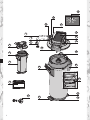
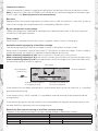
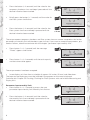
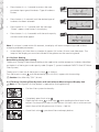
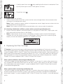
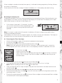
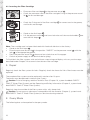
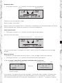
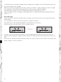
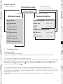
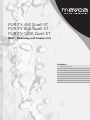
PURITY 450 Quell ST
PURITY 600 Quell ST
PURITY 1200 Quell ST
MDU – Measuring and Display Unit
Handbook
1 Definition of Terms
2 General Information
3 Commissioning a new filter with
MDU (Measuring and Display Unit)
4 Replacing the Filter Cartridge
5 Repair
6 Query Mode
7 Troubleshooting
19
9
50%
0
40
10
20
10
30
21
4
8
14
7
5
6
3
20
18
2
1
16
16
15
11
PURITY 450 Quell ST
PURITY 600 Quell ST
PURITY 1200 Quell ST
12
17
2
12
13
1 Definition of Terms
1
2
3
4
5
6
7
8
9
10
Pressure Vessel
Filter Cartridge
Pressure Vessel Lid
Connector Head
(optionally with Measuring Unit)
Display Unit (optional)
Inlet Hose
Inlet Valve on Inlet Hose (Chapter 12)
Terminal Device Connection
Flush Valve with Water Outlet
Connection of Outlet Hose
11
12
13
14
15
16
17
18
19
20
21
Filter Change Sticker
Kick Loops
Ejector Base
Display of the Display Unit (optional)
Lock
Mantle Handle
Reducer 1“– 3/4“
Transport Protective Cap
By-pass Screw
Lid Handle
Flush Hose
2 General Information
Before commissioning or replacing the filter, please read the system handbook for the PURITY Quell
ST Water Filter System. There you will find detailed information on operating and safety notes, maintenance, troubleshooting and technical data.
You will find instructions on how to flush the system in the PURITY Quell ST system handbook.
3 Commissioning a new filter with MDU (Measuring and Display Unit)
3.1 By-Pass Setting for Filter Systems with Measuring and Display Unit
•
Identify the local temporary hardness in gpg (grains per gallon) or rather mg/L (CaCO3 mg/l)
using the enclosed temporary hardness test.
•
Check the by-pass setting on the by-pass screw 19 .
Note: A 30% by-pass setting has been made in the factory, and must be changed to suit the local
temporary hardness and the application (Chapter 7, system handbook PURITY Quell ST Water Filter
System).
3.2 Commissioning the Filter Systems with Measuring and Display Unit
Representation in operating mode
Bar Display
Local Temporary
Hardness Set
14
30 %
gpg
1022
US
gaL
10.12.08
Available residual capacity
Date Field: Installation or
in US gallons
last filter change date
By-Pass Proportion
Flow Symbol
3
Temporary hardness
The local temporary hardness in gpg (grains per gallon) set during installation of the filter system.
Note: If necessary, the units of hardness can also be set to international degrees of hardness mg/L
(CaCO3 mg/l), see Selecting the units of measurement.
Bar chart
Representation of the remaining capacity using bar charts. After installation of a new filter system or
after a filter change, the symbolised funnel is completely filled with 10 bars.
By-pass proportion in percentage
The by-pass proportion is defined as the proportion of decarbonised water in the total amount of
filtrate and is indicated in percent.
Flow symbol
When water is removed via the filter system, a graphic snake is shown in the display.
Available remaining capacity of the filter cartridge
The remaining capacity of the filter cartridge is shown in US gallons or rather in litres.
When water is removed, it counts backwards in 1 US gallons or rather litre stages. If the cartridge is
already exhausted, the capacity is indicated as being negative by flashing.
With a remaining capacity of 20 % the last two bars in the bar chart start to flash.
With a remaining capacity of 10 % the last bar in the bar chart flashes with the two change arrows.
From a remaining capacity of 0 % the negative bars and the change arrows flash alternately with
the remaining capacity shown in negative.
Bar Display
Local Temporary
Hardness Set
14
Change arrow
30 %
gpg
135
US
gaL
By-Pass Proportion
10.12.08
Available residual capacity
Date Field: Installation or
in US gallons or litres
last filter change date
If the monthly limit has been reached up to a month before expiry of the set time limit, it is signalled
by the date field flashing.
If the monthly limit is 100% reached, it is signalled by alternate flashing of the date field and the
change arrows.
If the remaining capacity and the monthly limit are exceeded, the negative remaining capacity and
the date field flash alternately with the change arrows.
Date of the filter commissioning or last filter cartridge change
The date of filter commissioning or last filter cartridge change is indicated as follows:
American units of measurement
Example: 10.28.08
10
Month, here October
28
Day, here the 28th day
08
Year, here 2008
4
International units of measurement
Example: 28.10.08
28
Day, here the 28th day
10
Month, here October
08
Year, here 2008
Parameterisation
The following parameters have to be entered:
Number of gpg (grains per gallon) or rather mg/L (CaCO3 mg/l).
• Filter system size (03Typ = PURITY 450, 06Typ = PURITY 600 or 12Typ = PURITY 1200).
Temporary hardness
20
03
gpg
12
Filter System Size
US
gaL
Typ
10.12.08
Exhaustion after months
Date field
•
Type of hardness
The standard setting is gpg.
If necessary, the type of hardness can be set to international degrees of hardness mg/L
(CaCO3 mg/l), see Selecting the units of measurement.
•
Reminder function filter usage period in months
Irrespective of the remaining capacity display function, you can set a monthly limit of 2–12
months to activate a reminder function for filter replacement. If the monthly limit has been
reached up to a month before the export of the set time limit, it is signalled by the date field
flashing. Factory set to 12 months.
Example: Setting 9 months, the date field starts to flash in the display after 8 months.
To operate the display unit it has to be removed from the connecting
fittings. Slide the display housing up approx. 0.4 inches (10 mm) and
pull off the display unit to the front.
The display unit is operated using a button on the back of the display unit.
Selecting the units of measurement
You can choose between American and international units of measurement in the display.
For American units of measurement, select gpg (unit of measurement for water hardness); the
unit of volume and the date format are then automatically displayed in US gallons and MM.DD.YY
respectively.
For international units of measurement, select mg/L (unit of measurement for water hardness); the
unit of volume and the date format are then automatically displayed in litres and DD.MM.YY respectively.
Parameter input temporary hardness and filter system size
At this level, parameters needed for operation are set manually. The local temporary hardness of the
tap water and the filter system size are entered, the maximum cartridge useful life (monthly limited)
is entered and the type of hardness is set. After this, the parameters must be accepted.
•
Press the button (> 4 seconds) until the value for temporary hardness flashes.
> 4 sec
10
30
gpg
12
US
gaL
Typ
10.12.08
5
•
•
Press the button (> 2 seconds) until the value for the
temporary hardness rises and keep it pressed until the
desired value has been reached.
> 2 sec
13
12
13
Briefly press the button (< 1 second) until the value for
the filter system size flashes.
Press the button (> 2 seconds) until the value for the
filter system size rises and keep it pressed until the
desired value has been reached.
> 2 sec
13
US
gaL
US
gaL
12
US
gaL
Typ
10.12.08
12
gpg
Typ
10.12.08
12
gpg
12
•
30
gpg
Typ
10.12.08
The set parameters temporary hardness and filter system size can now be accepted or the further
parameters of monthly limit and hardness type also set. If you want to accept the parameters, proceed as follows, otherwise continue with the chapter “parameter input monthly limit“.
•
•
Press button 1 x (< 1 second) until the message
“Reset“ appears and flashes.
13
Press button 1 x (> 2 seconds) until the total capacity
and the current date appear.
> 2 sec
13
12
gpg
Typ
US
gaL
10.12.08
US
gaL
10.12.08
gpg
1747
The set parameters have been accepted.
•
Insert display unit from front at a height of approx. 0.4 inches (10 mm) and slide down.
The loops on the display part must be inserted in the grooves on the measuring head.
Continue with Chapter 3.4 Flushing / Draining for Filter Systems with and without Measuring and
Display Unit.
Parameter input monthly limit
•
Press button 2 x (< 1 second) to access the next
parameter input monthly limit. Monthly limit flashes.
•
6
Press the button (> 2 seconds) until the value for
the monthly limit rises and keep it pressed until the
desired value has been reached.
13
12
> 2 sec
13
12
gpg
US
gaL
12
10.12.08
12
gpg
US
gaL
Typ
Typ
10.12.08
•
•
Press button 2 x (< 1 second) to access the next
parameter input type of hardness. Type of hardness
flashes.
> 2 sec
> 2 sec
Press button 3 x (< 1 second) until the message
“Reset“ appears and flashes in the display.
•
Press button 1 x (> 2 seconds) until the total capacity
and the current date appear.
13
13
12
gpg
12
Press button (> 2 seconds) until the desired type of
hardness has been selected.
•
13
US
gaL
10.12.08
12
gpg
Typ
Typ
US
gaL
10.12.08
US
gaL
10.12.08
gpg
1747
Note: If no input is made within 30 seconds, the display will return to operating mode without
accepting amended parameters.
•
Insert display unit from front at a height of approx. 0,4 inches (10 mm) and slide down. The
loops on the display part must be inserted in the grooves on the measuring head.
3.3 By-Pass Setting
Determining the by-pass setting
The by-pass setting is identified according to the application and the temporary hardness identified
on the basis of the by-pass and capacity table (Chapter 7, system handbook PURITY Quell ST Water
Filter System).
The by-pass is then set on the by-pass screw 19 as follows:
Turn the by-pass screw 19 until the desired by-pass (0–50%) agrees with the marking.
! Caution: Use Allen key 7/32” (6 mm).
3.4 Flushing / Draining Filter Systems with and without Measuring and Display Unit
! Note: A 2.6 US gallon (10 litre) bucket is required for flushing/draining.
•
Position filter system horizontally.
•
•
Completely open flush valve 9 .
Open the inlet valve 7 at inlet hose 6 while holding the flush hose in the
bucket. Flush quantity at least 2.6 US gallons (10 litres) with a minimum volumetric flow of 0.8 US gallons/min (3 l/min = 180 l/h).
•
Close flush valve 9 , put down filter and empty bucket.
7
•
•
•
Carefully open flush valve 9 while holding the flush hose in the bucket. Flush
quantity once again at least 2.6 US gallons (10 litres).
•
Close flush valve 9 .
Check system for any leaks.
Note installation date of the filter system and the next exchange date on the enclosed sticker
and attach it to the pressure vessel.
Note: There is space for several stickers on the pressure vessel. Apply the new sticker with the
installation date at the top position.
Note: Filter systems without measuring and display units are now ready for operation.
3.5 Checking initialisation of filter systems with a measuring and display unit
•
By-pass setting in percent, remaining capacity in US gallons or rather litres, capacity bars and
the current date must be shown in the display.
•
Note: If these values are not shown in the display, the filter system must be flushed again
(Chapter 3.4) until the values are shown in the display. Filter systems with a measuring and
display unit are now ready for operation. Cf. Chapters 7.6 to 7.8.
13
30 %
gpg
2346
US
gaL
10.12.08
4 Replacing the Filter Cartridge
! Caution: During the exchange, carefully examine all dismantled parts! Faulty parts must be
exchanged and dirty parts should be cleaned. Read the Operating and Safety Information (Chapter 3,
system handbook PURITY Quell ST Water Filter System) prior to replacement. After the product has
been stored and transported at temperatures below 32° F (0°C), it must be stored with the original
packaging open for at least 24 hours before commissioning at the ambient temperatures stated in
Chapter 10, system handbook PURITY Quell ST Water Filter System.
Filter systems without a measuring and display unit
The filter cartridge must be replaced after 6–12 months, at the latest 12 months after commissioning, irrespective of the level of exhaustion of the filter system. If the capacity of the filter cartridge
has already been exhausted (Chapter 7, system handbook PURITY Quell ST Water Filter System),
it must be exchanged earlier.
Filter systems with a measuring and display unit
The filter cartridge must be replaced no later than 12 months after commissioning, irrespective of
the level of exhaustion of the filter system. If the capacity of the filter cartridge has already been
exhausted (Chapter 7, system handbook PURITY Quell ST Water Filter System), it must be replaced
earlier.
8
If the cartridge is already exhausted, the capacity is indicated as being negative by flashing. No bars
are shown in the display.
If the monthly limit for the cartridge has been exceeded, this is indicated by the date flashing.
13
12
gpg
33
US
gaL
Typ
10.12.08
Resetting the display unit
To operate the display unit it has to be removed from the connecting fittings. Slide the display housing up approx. 0.4 inches (10 mm) and pull off the display unit to the front. The display unit is operated using a button on the back of the display unit.
•
If this button is pressed (> 10 seconds), the data
set on initial installation will be accepted again, and
the capacity, by-pass setting and input date are all
updated.
> 10 sec
10
12
gpg
12
US
gaL
Typ
10.12.08
Note: If no input is made within 30 seconds, the display will return to operating mode without
accepting amended parameters.
Insert display unit from front at a height of approx. 0.4 inches (10 mm) and slide down. The loops on
the display part must be inserted in the grooves on the measuring head.
4.1
•
•
•
Removing the Filter Cartridge
Switch off the power supply of the terminal equipment (remove plug).
Close inlet valve 7 at inlet hose.
Remove pressure from the system by opening flush valve 9 .
Note: Insert the free end of the flush hose in a bucket. If the escaping water is more than
0.13 US gallons (0.5 litres), the inlet valve is not completely closed or is blocked with scale.
•
•
•
•
•
•
•
•
•
Close flush valve 9 .
Stand on the kick loops 12 .
Open the pressure vessel lid by pressing the lock 15 and turning it anticlockwise as far as it will go. The filter cartridge is released by pressing on the
mantle handles.
Place the pressure vessel lid 3 vertically on the lid handle 20 .
Turn the pressure vessel on the mantle handles anticlockwise as far as it will go.
Note: Remain standing on the kick loops 12 with both feet.
Take your feet off the kick loops and press the pressure vessel down with both hands on the
mantle handles 16 .
Remove exhausted filter cartridge 2 from the pressure vessel 3 .
Place the exhausted filter cartridge 2 in the sink with the connection facing down to drain the
remaining water (> 5 min.).
Place the transport protection cap 18 of the new filter cartridge on the exhausted filter cartridge
and send it back in the original packaging.
9
4.2 Inserting the Filter Cartridge
•
•
Place new filter cartridge 2 in the pressure vessel 1 .
Check the connector seat of the filter cartrigde O-ring in the pressure vessel
lid 3 for dirt and damage.
•
Check the O-ring seal of the filter cartridge
and for dirt and damage.
•
•
Stand on the kick loops
Lift the pressure vessel
over the kick loops 12 .
2
for correct seat in the groove,
12 .
1
and turn clockwise until the mantle handles
16
are
Note: The cartridge seat has been lubricated with food-safe lubricant at the factory.
•
Stand on the kick loops 12 .
•
Place the pressure vessel lid 3 in the position “INSERT“ on the pressure vessel 1 with the
lock 15 in the appropriate groove.
•
Press the pressure vessel lid 3 down and turn clockwise until it engages.
•
Switch on power supply to the terminal device (plug).
To flush/drain the filter systems with and without a measuring and display unit carry out the steps
described under Chapter 3.4 to commission the new filter cartridge.
5 Repair
Regularly check the filter system for leaks. Regularly check the hoses for kinks. Bent hoses must be
replaced.
The complete filter system must be replaced in rotation after 10 years.
The hoses must be replaced in rotation after 5 years.
! Caution: Prior to changing, read the Technical Data (Chapter 10, system handbook PURITY
Quell ST Water Filter System) and the Operating and Safety Information (Chapter 3, system handbook PURITY Quell ST Water Filter System).
Regularly clean the outside of the filter system with a soft, damp cloth.
! Caution: Do not use any substances incompatible with the material (Chapter 3, system handbook PURITY Quell ST Water Filter System) or abrasive cleaning materials.
6 Query Mode
The following data can be queried in the query mode:
10
Production data
•
Briefly press button 1 x (< 1 second), the following message appears.
ID Level
Production year
08
00823
US
gaL
07.10.19
Serial Appliance Number
Battery Service Life
Production year: Example 08 = 2008
Device number: consecutive
Battery useful life: Example 07.10.19 = The battery in the display unit will be exhausted on 07/10/19
and the complete filter system has reached its maximum usage period.
Total volume meter
•
Briefly press button 2 x (< 1 second), the following message appears.
00 level current data (today)
00 Indicator for current level
Filter system size
00
7784
12
US
gaL
Typ
10.12.08
Total volume meter
Current date
The total volume meter is managed at this level; it counts up from 0 irrespective of the cartridge
change.
Memory Call-Up
In the Memory Call-Up mode, the data of the last 4 filter cartridges used can be called up.
•
Briefly press button 1 x (<1 second) until the following message appears.
-1, -2, -3, -4 level – data of the cartridges used before the current one.
Temporary hardness
14
6619
By-pass
30 %
gpg
US
gaL
10.12.08
Total meter reading when changing
the filter cartridge
Cartridge indicator
alternating
1
Type
12
0
US
gaL
Typ
10.12.08
Date of inserting the cartridge
At the top left, the indicator for the filter cartridge (-1 for previous filter cartridge) is displayed alternately with the temporary hardness set and the hardness unit. At the top right, the filter system
size is displayed alternately with the by-pass setting (display 1 s indicator, 1 s temporary hardness),
11
at the bottom left, the meter reading when changing the cartridge (-1) and at the bottom right, the
installation date of the cartridge.
Meaning: the filter cartridge most recently used was a PURITY 1200 cartridge, the filter cartridge
was inserted on 10/12/08 and operated up to a meter reading of 6619 US gallons.
The temporary hardness set was 14°gpg and the by-pass measured was 30%.
The same applies to the cartridge(-2), preceding filter cartridge and the other preceding filter cartridges -3, -4.
Error Messages
The error level E1 indicates whether and from when until when an error has occurred at the water
intake meter.
E1 is activated as soon as the current by-pass is greater than 60%.
The word Start is then displayed together with the date of occurrence.
Please check that the non-return valve is seated correctly.
E1
alternating
US
gaL
06.07.08
E1
US
gaL
06.07.08
As soon as the current by-pass setting is in the range between 0 and 60% again, the error has
ended and the Stop date is added. At error level 01 the Stop and Start display alternates every second.
Error level E2 indicates whether and from when until when an error has occurred at the outlet water
meter. Display is similar to level E1.
12
Program Overview
Operating mode
20 sec. no activity
Temporary hardness •
Capacity • By-pass •
last filter change data
1 x button
Retrieval mode
ID-Information
ÀÀÀ
00 Current level
ÀÀÀ
-1 History level 1
ÀÀÀ
-2 History level 2
ÀÀÀ
-3 History level 3
ÀÀÀ
-4 History level 4
ÀÀÀ
E1 Error inlet metre
ÀÀÀ
E2 Error drainage metre
30 sec. no acitivity
no Parameter acceptance
Press button 4 seconds
Parameterisation
Temporary hardness set of 2 sec.
ÀÀÀ
Device type
set of 2 sec.
ÀÀÀ
RESET
set of 2 sec.
ÀÀÀ
Parameter acceptance
ÀÀÀ
Month limit
ÀÀÀ
Hardness type
set of 2 sec.
set of 2 sec.
7 Troubleshooting
7.1 No water flow
7.1.1 Cause: Water intake closed.
Troubleshooting: Open water intake on the upstream stop valve or inlet valve on inlet hose.
7.1.2 Cause: Confused inlet and outlet installation.
Troubleshooting: Check and, if necessary, correct the assembly situation (Chapter 4.3, system handbook PURITY Quell ST Water Filter System) of the intake hose 6 with intake valve 7 and terminal
device connection 8 with flush valve 9 . Pay attention to the direction of flow according to the
arrows on the connector head 4 .
7.1.3 Cause: Non-return valve in the entrance to the connector head not seated correctly.
Troubleshooting: Check direction of flow as in Chapter 7.1.2 and seat of the non-return valve and correct if necessary (Chapter 4.3, system handbook PURITY Quell ST Water Filter System). Flush filter
system again (Chapter 3.4).
! Caution: The following faults may be remedied only by trained or authorised personnel.
13
7.2 No or low water flow in spite of open water intake
Cause: Mains pressure too low.
Troubleshooting: Check mains pressure. If the fault continues, check the filter system and filter
cartridge and change if necessary.
! Caution: Prior to changing, read the Technical Data (Chapter 10, system handbook PURITY
Quell ST Water Filter System) and the Operating and Safety Information (Chapter 3, system handbook PURITY Quell ST Water Filter System).
7.3 Leak at Screwed Connections
Cause: Screwed connections not fitted correctly.
Troubleshooting: Check mains pressure. Check all screwed connections and mount according to
Chapter 4.2, system handbook PURITY Quell ST Water Filter System.
If the fault continues, exchange filter system.
! Caution: Prior to changing, read the Technical Data (Chapter 10, system handbook PURITY
Quell ST Water Filter System) and the Operating and Safety Information (Chapter 3, system handbook PURITY Quell ST Water Filter System).
7.4 Leak after Filter Replacement
Cause: O-ring at the filter cartridge is not seated correctly.
Troubleshooting: Check correct seat of the O-ring (Chapter 4.3, system handbook PURITY Quell ST
Water Filter System).
! Caution: Prior to changing, read the Technical Data (Chapter 10, system handbook PURITY
Quell ST Water Filter System) and the Operating and Safety Information (Chapter 3, system handbook PURITY Quell ST Water Filter System).
7.5 No Display Function
Cause: Battery drained.
Troubleshooting: Replace display unit (Order number see Chapter 11, system handbook PURITY
Quell ST Water Filter System).
Note: When replacing the display unit, follow the enclosed Manual.
7.6 Data in Display Flashing
Cause: Monthly limit expired or the remaining capacity of the filter cartridge is exhausted
(Chapter 3.2).
Troubleshooting: Replace filter cartridge (Chapter 4).
7.7 By-pass setting in the display does not agree with the setting of the by-pass screw
(cf. 7.8/7.9)
Cause: Filter was not commissioned correctly.
Troubleshooting: Flush filter again (Chapter 3.4). Check data in the display after flushing
(Chapter 3.5).
7.8 By-pass setting in the display does not agree with the setting of the by-pass screw
(cf. 7.7/7.9)
Cause: Flow rate too high.
Troubleshooting: Slightly open flush valve during flushing.
! Caution: Don‘t forget the bucket! Flush filter again (Chapter 3.4). Check data in the display after
flushing (Chapter 3.5).
14
7.9 By-pass setting in the display does not agree with the setting of the by-pass screw
(cf. 7.7/7.8)
Cause: Valve strip of the by-pass setting not set correctly.
Troubleshooting: Flush filter system again and readjust by-pass screw (Chapter 3.3).
7.10 No by-pass value is displayed after operation for a long time
Cause: Drop quantity is removed.
Troubleshooting: Remedy gradual leak on the consumer side and flush filter system again
(Chapter 3.4).
15
PN: 536829-MAE
MAVEA LLC
675 Tollgate Road, Suite G
Elgin, IL 60123
USA
www.mavea.com
[email protected]
Information in the instruction for use subject to change