1
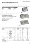
Operating Instructions EMK Single-core mineral-insulated heating circuit, laser-welded type 27-3641-.2../.... 1. Use for the Intended Purpose 3. Marking and Safety Instructions The laser-welded single-core mineral-insulated heating circuit type 27-3641-.2../…./…. forms a mineralinsulated, water-proof, electric sheath heating with a sheath material made of 1.4541 or 2.4816. These heating circuits are used for heating and maintaining a constant temperature in pipes, containers and similar equipment. Marking 2. Product Description Particularly important points in these instructions are marked with a symbol: DANGER draws attention to a danger which will lead to death or serious injury if not avoided. EMK heating cable WARNING draws attention to a danger which can lead to a death or serious injury if it is not avoided. 2. 1. 1. Heating conductor 3. CAUTION draws attention to a danger which can lead to an injury if it is not avoided. 2. Magnesium oxide insulation (MgO) 3. Outer sheath ATTENTION draws attention to measures to prevent damage to property. EMK heating circuit 4. 2. 3. 1. Note Important instructions and information on effective, economical and environmentally compatible handling. Safety Instructions 4. 3. 2. TA Tserv 1. EMK heating cable 2. Connection sleeve 3. Cold lead 4. Cable gland The operating temperatures that can be reached depend not only on the heating circuit output but also on the following operating conditions and can influence them: thermal conductivity of the material to be heated, thermal conductivity of the medium to be heated, type and strength of the insulation and its values. 21-3641-7D0001-06/2013-BARTEC WerbeAgentur-349784 The heating circuits in this series can be used for a regulated operating state up to 650 °C at the heating conductor. Resistance to chemicals: The outer sheath made of VA 1.4541 or 2.4816 can be used in many cases but its utilisation is only conditional where there are chemical liquids and gases. Before commissioning the heating circuit, the owner/ managing operator must check this utilisation condition. Before commissioning, please check the marking on the heating circuit to make sure that it is suitable for the intended usage. When using electrical equipment, die relevant installation and operating regulations must be complied with (e.g. Directive 1999/92/EC, Directive 94/9/EC, EN 60079-0, EN 60079-14, EN 60079-30-2, EN 61241-0 or EN 61241-14 and the DIN VDE 0100 series or other relevant national regulations). Installation should be performed by a qualified electrician who has done additional training for electric trace heating systems in hazardous areas. It is essential to follow the directions in the operating instructions provided by the manufacturer. All generally applicable statutory regulations and other binding directives relating to workplace safety, accident prevention and environmental protection must be adhered to. An incorrect installation of the trace heating and the neighbouring system parts or damage to the heating circuit can cause short-circuiting and the risk of fire during operation. The owner/operating manager of an electric system in a hazardous area must keep the operating equipment in good condition, operate it correctly, monitor it and do the required maintenance and repairs. Phone:+497931597-0 [email protected] BARTEC GmbH Max-Eyth-Straße 16 Germany 97980 Bad Mergentheim Fax: +497931597-119 www.bartec-group.com Reservation Technical data subject to change without notice. No claims for damages arising from alterations, errors or misprints shall be allowed. EN 1/6 Operating Instructions EMK Single-core mineral-insulated heating circuit, laser-welded type 27-3641-.2../.... 4. Guidelines for handling heating circuits Note 4.1. Storage The EMK heating circuits must be stored in protected, clean and dry areas. It must be ensured that the heating circuit is protected from mechanical damage and atmospheric influences. The storage temperature must be between -20 °C and +60 °C. 4.2. Handling The following points must be observed when unrolling: - Avoid excessive pulling. - Avoid bending and crushing the cables. - Do not step on the heating circuit or use it as a climbing loop. -To prevent damage to the insulation, particular care must be taken with sharp corners and edges, such as for example on flanges or retaining devices. - It is not permissible to drive over the cables with vehicles or auxiliary means of transport. It is not permissible to have heating circuits cross over or be in contact with each other because this can increase the temperature beyond the limit or max. permissible operating temperature. 5. Mounting and Installation Note 5.1. Installation Instructions 5.2. Inspection before Mounting Before starting to install a heating circuit, measure the insulation resistance. On the basis of the resistance measurement check if the supplied heating circuit conforms to the project planning. 5.3. Installing the heating circuit EMK heating circuits are fixed in position with stainless-steel fixing straps or cable ties. Depending on conditions, the heating circuit can be placed longitudinally along the object to be heated or wound spirally around it. When installing, the minimum bending radius relative to the outer diameter of the heating cable must be observed: Short designation Resistance [Ω/ km] Outer diameter Heating cable Bending radius EMK VA 010K NiCr 10000 3.2 mm 16 mm EMK VA 6300 NiCr 6300 3.2 mm 16 mm EMK VA 4000 NiCr 4000 3.2 mm 16 mm EMK VA 2500 NiCr 2500 3.6 mm 18 mm EMK VA 1600 NiCr 1600 3.8 mm 20 mm EMK VA 1000 NiCr 1000 4.1 mm 21 mm EMK VA 630 NiCr 630 4.5 mm 23 mm EMK VA 400 NiCr 400 5.0 mm 25 mm EMK VA 250 NiCr 250 5.6 mm 28 mm EMK VA 160 NiCr 160 6.5 mm 33 mm EMK VA 1600 CuNi 1600 3.2 mm 16 mm EMK VA 1000 CuNi 1000 3.4 mm 17 mm The surface of the object to be heated must be dry and clean. EMK VA 630 CuNi 630 3.7 mm 18.5 mm EMK VA 400 CuNi 400 4.0 mm 20 mm Check the intended operating voltage. EMK VA 250 CuNi 250 4.4 mm 22 mm The temperature must not drop below the minimum installation temperature. EMK VA 160 CuNi 160 4.9 mm 24.5 mm The cables must not be painted over. The minimum bending radius must be observed. The minimum installation spacing must be observed. When bending, a minimum spacing of 20 mm must be maintained between the heating conductor/cold lead and sleeve/gland before the bend: Bending radius Sleeve 20 Heating conductor side 20 Cold tail side R Cold lead Sleeve R When installing the laser-welded heating circuits, make sure that they do not cross over or touch each other as they could then overheat or cause fires. 20 Bending radius of cold tail R 21-3641-7D0001-06/2013-BARTEC WerbeAgentur-349784 The heating circuit should be laid longitudinally along the pipe in order to improve heat conductivity. Cross-section (mm2) Cold lead diameter (Ø) Minimum bending radius (R) 2.5 4.9 mm 25 6.0 6.1 mm 31 Phone:+49 7931 597-0 [email protected] BARTEC GmbH Max-Eyth-Straße 16 Germany 97980 Bad Mergentheim Fax: +49 7931 597-119 www.bartec-group.com Reservation Technical data subject to change without notice. No claims for damages arising from alterations, errors or misprints shall be allowed. EN 2/6 Operating Instructions EMK Single-core mineral-insulated heating circuit, laser-welded type 27-3641-.2../.... When installing, care must be taken to assure good surface contact and heat transmission. Heatconductive material can be used to bridge critical points (edges or corners). Before insulating, cover the heating circuit with aluminium or VA foil. On the one hand, this will improve the distribution of heat on the object and on the other hand it will protect against the penetration of insulating material between the heating circuit and the object to be heated. The presence of insulation parts between the heating circuit and the object increases temperatures in this area and can destroy the heating circuit. The user must check that the cover has been put on properly and correctly. Cable gland Metallic components which come into contact with the heating circuit must be integrated into the safety measures (protective earthing) required under Safety Class I. A more detailed explanation can be found in VDE 0100. PTFE washer The cold leads are intended for fixed connection and are connected through glands with flexible connection strands into an Ex e/Ex d approved terminal box. The metallic outer sheath is earthed by means of the integrated protective earth conductor connection. Ex e terminal box The glands are either screwed in through a suitable threaded hole in the terminal box or fixed in place by means of a through-hole and the included locknut. When connecting, the requirements in the standards and regulations under “1. Safety Instructions” must be observed. The permissible temperature range in the connecting area is -55 °C to +70 °C. Locknut The minimum permissible installation temperature is -55 °C. Torques to tighten the gland and the washer: Torque for the PTFE M20 and M25 washers: 20 Nm Torque for the M20 gland: 30 Nm Torque for the M25 gland: 35 Nm Maximum permissible borehole diameter to enable the insertion of the cable glands into the terminal box: Max. Ø 20.5 mm for M20 gland 21-3641-7D0001-06/2013-BARTEC WerbeAgentur-349784 Max. Ø 25.5 mm for M25 gland 5.4. Installation on fittings, flanges and pumps Always install the heating circuits on fittings, valves etc. in a way that ensures that they can be easily accessed and replaced during maintenance and repair work without there being a need to break up heating circuits. This is best achieved by ensuring that the heating cable loop is sufficiently large. The higher heat losses at fittings, valves etc. increase the length of heating circuit that is required. This additional requirement can be found in the project planning specifications. The heating circuits should be mounted so that the contact with the surface to be heated is as close as possible. Where such contact is not possible, for example on valves, suitable heat conducting cladding made of temperature-resistant metal foil or other heat-conducting materials may be used. Phone:+497931597-0 [email protected] BARTEC GmbH Max-Eyth-Straße 16 Germany 97980 Bad Mergentheim Fax: +497931597-119 www.bartec-group.com Reservation Technical data subject to change without notice. No claims for damages arising from alterations, errors or misprints shall be allowed. EN 3/6 Operating Instructions EMK Single-core mineral-insulated heating circuit, laser-welded type 27-3641-.2../.... Typical types of installation are shown in the following illustrations: Installation on valves 5.6. Installation 6.2. Residual Current operated Circuit-Breaker Disconnect all circuits before starting any installation or maintenance work. To switch off, all outer conductors, i.e. including the neutral conductor, must be disconnected from the power supply. It is essential to observe the markings on the heating circuit. Note Installation on supports Installation on pumps The supplied goods must be visually inspected and the insulation tested before installation. Check the markings on the heating circuits to ensure that they suit the ordered goods. Before and during installation: keep the heating cable and cold lead ends and also the trace heating connection components dry. Cable ends that are not connected must be closed off in the field using a suitable end termination. As a basic rule, the heating circuit must be affixed with mechanical and temperature stability to the workpiece to be heated to assure a reliable thermal coupling. The object provided with trace heating (work piece, plant part) must be clearly marked as such, once the thermal insulation has been installed, by affixing warnings and markings at suitable points and/or at regular intervals along the heating circuit. It is recommendable to operate the heating circuits with a residual-current-operated circuit-breaker (RCCB). In this case, an RCCB with a tripping current of 0.3 or 0.5 A should be used as significant working currents can arise when the temperature is too high and the heating circuit too long. The heating circuits are suitable for use only in earthed networks such as TT or TN. Utilisation in insulated networks is not possible. 7. Electrical Connection Observe the nominal voltage specified in the marking on the heating circuit. Operate the respective heating circuit only with the nominal voltage intended for it, which is de termined by the heating circuit design. When connecting the cold leads to external circuits, use enclosures and connection parts that are suitable for the respective application and have been installed correctly. 8. Inspection and Commissioning After installation, the insulation must be tested. Installation on pressure gauges For claims under guarantee it is essential to submit a correctly and fully completed acceptance test report. BARTEC´s standard Acceptance Test Report can be found in the “Assembly and Operation of EKL/EMK installation systems”documentation (www.bartec.de). 6. Electric Protective Equipment 5.5. Stretched Installation 21-3641-7D0001-06/2013-BARTEC WerbeAgentur-349784 6.1. Overcurrent Protection For overcurrent protection, please use only automatic circuit breakers which conform to the project planning and technical documents from BARTEC. Deviations from these can lead to false tripping of the automatic circuit break ers or impair the effectiveness of the over current protection device. When double laying the heating circuit, route along the“half-past four” and “half-past seven” positions on the pipe. When installing on horizontal pipes, do not lay the heating circuit at the lowest point. If protection units other than those specified in the project planning and BARTEC`s techni cal documents are to be used, please contact the technical department at BARTEC first. Phone:+49 7931 597-0 [email protected] BARTEC GmbH Max-Eyth-Straße 16 Germany 97980 Bad Mergentheim Fax: +49 7931 597-119 www.bartec-group.com Both after installing the trace heating and also after installing the thermal insulation, the following inspections must be performed and recorded in a test report. This test data must be submitted whenever a complaint is made. 8.1. Measurement of the Insulation Resistance This test procedure serves to establish if there is any damage to the heating circuit and if any errors have been made when installing connections or links. An insulation tester with a minimum test voltage of DC 500 V and a maximum test voltage of DC 1000 V is used. The insulation resistance per heating circuit must be at least 20 MΩ (in conformance to EN 62395-1) irrespective of length. Performing the Measurement: - The measurements are taken between the heating conductor and the outer sheath. 8.2. Inspection of the Electric Protective Equipment The requirements for protecting external circuits must be fulfilled. See “6. Electric Protective Equipment” in these instructions. Reservation Technical data subject to change without notice. No claims for damages arising from alterations, errors or misprints shall be allowed. EN 4/6 Operating Instructions EMK Single-core mineral-insulated heating circuit, laser-welded type 27-3641-.2../.... 8.3. Checking the Design Data After switching on, it is important to check the specifications determined when the trace heating system was designed, such as applied voltage, the levels of current that arise and the pipe temperature, with the measures and devices appropriate for that purpose. 9. Operation, Maintenance, Upkeep The owner/operating manager of an electric system must keep the operating equipment in good condition, operate it correctly in conformance to regulations, monitor it and do the required maintenance and repairs. Each piece of electric operating equipment must be selected for its suitability for use in the respective area. Before starting operation again, check conformance to the applicable laws and directives. The specified safety instructions must be observed before starting maintenance work or troubleshooting. 10. Approvals and Ex Protection Type Marking EC Type Examination Certificate ATEX Marking BVS 13 ATEX E 034 U II 2 G Ex e IIC Gb II 2 D Ex tb IIIC Db IECEx Certificate of Conformity IECEx BVS 13.0042U IECEx Marking Ex e IIC Gb Ex tb IIIC Db Applied Standards EN 60079-0:2009 EN 60079-7:2007 EN 60079-30-1:2007 EN 60079-31:2009 IEC 60079-0:2007-10 IEC 60079-7:2006-07 IEC 60079-30-1:2007-01 IEC 60079-31:2008 11. Technical Data Operating Voltage up to AC 500 V Nominal current with cold lead 2.5 mm2 up to 30 A with cold lead 6,0 mm2 up to 55 A Resistance Heating cable Cold lead Minimum bending radius 5 x conductor diameter 9.1. Troubleshooting Permissible operating temperature Special troubleshooting procedures are helpful in the detection of faults in electric trace heating systems installed under the thermal insulation. Cable terminations Cables Minimum installation temperature -55 °C The heating circuit can reach temperatures during operation which will cause burning when touched. This is why the heating circuit must not be touched when switched on. Suitable measures must be taken to protect people. In addition, the engineer who planned the electric trace heating systems should be consulted. Faults are often caused by mechanical damage, corrosion, overheating or the penetration of moisture. The inspections required before commissioning should be repeated as a basis for locating the fault(s).. 9.2. Repairs, Servicing -55 °C up to +70 °C -70 °C up to +650 °C 12. Service Address BARTEC GmbH Max-Eyth-Straße 16 97980 Bad Mergentheim Germany Phone: +49 7931 597-0 Fax: +49 7931 597-183 info.bartec.de www.bartec-group.com 21-3641-7D0001-06/2013-BARTEC WerbeAgentur-349784 The maintenance and repairs are performed in accordance with the standards and conditions specified under point “3. Marking and Safety Instructions” and, depending on the utilisation, the applicable rules laid down by the employers’ liability insurance association (BG) and other conditions relating to the respective application. The heating equipment and its regulation should be tested for correct functioning at least once a year. 160 Ω/km up to 10 kΩ/km 3 Ω/km up to 7 Ω/km Phone:+497931597-0 [email protected] BARTEC GmbH Max-Eyth-Straße 16 Germany 97980 Bad Mergentheim Fax: +497931597-119 www.bartec-group.com Reservation Technical data subject to change without notice. No claims for damages arising from alterations, errors or misprints shall be allowed. EN 5/6 Betriebsanleitung EMK Single-core mineral-insulated heating circuit, laser-welded type 27-3641-.2../.... 21-3641-7D0001-06/2013-BARTEC WerbeAgentur-349784 Declaration of Conformity Phone:+49 7931 597-0 [email protected] BARTEC GmbH Max-Eyth-Straße 16 Germany 97980 Bad Mergentheim Fax: +49 7931 597-119 www.bartec-group.com Reservation Technical data subject to change without notice. No claims for damages arising from alterations, errors or misprints shall be allowed. EN 6/6