1
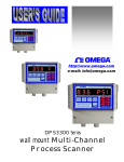
User’s Guide
Shop online at
omega.com SM
e-mail: [email protected]
For latest product manuals:
www.omegamanual.info
CN1511 SERIES
Wall Mounted PID and
On/Off Controller
omega.com [email protected]
Servicing North America:
U.S.A.:
Omega Engineering, Inc., One Omega Drive, P.O. Box 4047
Stamford, CT 06907-0047 USA
Toll-Free: 1-800-826-6342 (USA & Canada only)
Customer Service: 1-800-622-2378 (USA & Canada only)
Engineering Service: 1-800-872-9436 (USA & Canada only)
Tel: (203) 359-1660 Fax: (203) 359-7700
e-mail: [email protected]
For Other Locations Visit omega.com/worldwide
The information contained in this document is believed to be correct, but OMEGA accepts no liability for any errors it contains, and reserves
the right to alter specifications without notice.
SPECIFICATIONS .......................................................................................................................................................... 4
DESCRIPTION ................................................................................................................................................................ 5
THERMOCOUPLE OR RTD SELECTION................................................................................................................. 5
HOW TO RESET AND PROGRAM THERMOCOUPLE TYPE (OR RTD) .................................................................................. 5
FIGURE 1. THERMOCOUPLE/RTD SELECTION KEYS ..................................................................................................... 6
DISPLAY MODES........................................................................................................................................................... 6
RETAINING USER SETTINGS ON POWER DOWN................................................................................................ 6
FLOW CHART ................................................................................................................................................................ 7
'RAMP & SOAK PROFILE' SELECTION .................................................................................................................. 8
SETUP MODE................................................................................................................................................................. 8
ENTERING AND EXITING SETUP MODE: .......................................................................................................................... 8
HOW TO INCREASE/DECREASE PROGRAMMABLE VALUES IN SETUP .............................................................................. 8
PASSCODE ENTRY: .......................................................................................................................................................... 8
'PROGRAM CONTROLLER' MODE .......................................................................................................................... 9
SELECTING ON/OFF OR PID CONTROL .......................................................................................................................... 9
ENTERING ON/OFF VARIABLE ....................................................................................................................................... 9
On/Off Hysteresis (Dead-Band) ................................................................................................................................. 9
ENTERING PID VARIABLES ............................................................................................................................................. 9
Proportional band ...................................................................................................................................................... 9
Reset ......................................................................................................................................................................... 10
Rate........................................................................................................................................................................... 10
ENGINEERING UNITS (C/F) ........................................................................................................................................... 10
DISPLAY TIME ............................................................................................................................................................... 10
DISPLAY OPTION:.......................................................................................................................................................... 10
HEAT/COOL SETUP: ................................................................................................................................................... 11
RATE TIME-BASE:......................................................................................................................................................... 11
COLD JUNCTION ADJUSTMENT: ..................................................................................................................................... 11
THERMOCOUPLE CALIBRATION:.................................................................................................................................... 11
THERMOCOUPLE TYPE SELECTION: ............................................................................................................................... 12
‘PROGRAM LIMITS’ MODE: .................................................................................................................................... 12
PROCESS LIMITS (1 THRU 4): ......................................................................................................................................... 12
SELECTION OF LIMIT 3 AS PROCESS OR RATE LIMIT:..................................................................................................... 13
PROGRAMMING LIMIT 3: ............................................................................................................................................... 13
As Process Limit:...................................................................................................................................................... 13
As Rate Limit: ........................................................................................................................................................... 13
SELECTION OF LIMIT 4 AS PROCESS OR DEVIATION LIMIT: ........................................................................................... 13
PROGRAMMING LIMIT 4: ............................................................................................................................................... 13
As Process Limit:...................................................................................................................................................... 13
As Deviation Limit:................................................................................................................................................... 13
CONFIGURE TIMING MODE............................................................................................................................................ 14
TIMERS 1 AND 2: ........................................................................................................................................................... 14
RELAY DEADBAND: ...................................................................................................................................................... 14
CONFIGURING LIMITS NORMALLY OPEN/NORMALLY CLOSED: .................................................................................... 14
RELAY LATCHING/NON LATCHING:............................................................................................................................... 14
AUDIO ALARM ON/OFF:................................................................................................................................................ 15
'VERIFY' MODE:.......................................................................................................................................................... 15
PROFILE MODE (ENTERING RAMP & SOAK): ................................................................................................... 15
Page 2
RAMP/SOAK PROFILE EXAMPLE .......................................................................................................................... 16
EXTERNAL CONTROL RELAY INSTALLATION FOR RAMP/SOAK OPERATION..................................... 17
Figure 3. Solid State relay hookup for controller output......................................................................................... 17
VARIOUS CONTROLLER MODES........................................................................................................................... 17
CONTROLLER RUN MODE ............................................................................................................................................. 17
CONTROLLER HOLD MODE .......................................................................................................................................... 17
CONTROLLER STOP MODE ............................................................................................................................................ 18
CONTROLLER MANUAL MODE .................................................................................................................................... 18
RATE............................................................................................................................................................................... 18
RATE ALARM: ............................................................................................................................................................... 18
RESETTING RATE ALARM: ............................................................................................................................................ 18
SETPOINT DEVIATION: ............................................................................................................................................ 19
DEVIATION ALARM:...................................................................................................................................................... 19
RESETTING DEVIATION ALARM: ................................................................................................................................... 19
PROCESS ALARMS ..................................................................................................................................................... 19
DISPLAYING: ................................................................................................................................................................. 19
RESETTING: ................................................................................................................................................................... 19
ELECTRO-MECHANICAL RELAY OPTION ....................................................................................................................... 20
Figure 4. Electro-mechanical Relays Hookup Example........................................................................................... 20
OPEN COLLECTOR OPTION ............................................................................................................................................ 20
Figure 5. Open Collector Hookup Example ............................................................................................................ 20
TIMERS .......................................................................................................................................................................... 20
RESETTING TIMERS: ...................................................................................................................................................... 21
TIMER MODES............................................................................................................................................................. 21
TIMER MODE #0............................................................................................................................................................ 21
TIMER MODE #1............................................................................................................................................................ 21
TIMER MODE #2............................................................................................................................................................ 21
ELAPSED TIME........................................................................................................................................................... 21
HOW TO RESET ELAPSED TIME ...................................................................................................................................... 21
HIGH AND LOW PEAKS ............................................................................................................................................ 21
HOW TO RESET HIGH & LOW PEAK READINGS.............................................................................................................. 22
OUTPUT STATUS:........................................................................................................................................................ 22
POWER........................................................................................................................................................................... 22
SIGNAL CONNECTION .............................................................................................................................................. 22
OUTPUT CONNECTOR PIN ASSIGNMENT .......................................................................................................... 22
TABLE 1. OUTPUT CONNECTOR PIN ASSIGNMENT ...................................................................................................... 23
FIG 6. CN1511 SERIES TERMINAL COMPARTMENT........................................................................................ 24
DIRECT INTERFACE TO UNIVERSAL RELAY MODULE ................................................................................. 24
DIRECT INTERFACE TO UNIVERSAL RELAY MODULE ................................................................................. 25
MOUNTING ................................................................................................................................................................... 26
Page 3
SPECIFICATIONS
Typical @ 25 C and rated supply voltage unless otherwise specified.
INPUTS:
•
•
•
Input types: J,K,T,E,R,S,B t/c, RTD, Voltage, Millivolt, Current & thermistor
Cold junction compensation error: +/- 0.5C max (10C to 40C)
Open thermocouple indication: ‘OPEN TC’ displayed
OPTIONS:
•
•
•
•
240Vac @ 50 Hz Power Supply
15Vdc @ 1000ma. Power Supply
Open Collector output: 6 open collector transistors @ 50ma. sink each
Relay output: 4 SPST 1 Amp. @ 28Vdc, 0.5 Amp. @ 120Vac (resistive load)
(for 220 Vac units only 0.25Amp.@ 240Vac (resistive load))
2 open collector transistors @ 50ma. sink each
ACCURACY:
•
•
Temperature resolution: 1 C/1 F, 0.1C for Thermistor
0.1% of Full Scale (Base metal T/C), 0.5% others
ANALOG TO DIGITAL CONVERSION:
• 4 1/2 Digit (20000 count) A/D conversion.
• Dual slope integrating converter.
• Conversion Rate: 7 /sec. typical
POWER REQUIREMENTS:
• 120Vac, 0.2 Amp. @ 60 Hz
DIMENSIONS:
• Case: 7.55"W x 6.29"H x 4.05"D
• IP65 rated plastic enclosure
• Weight: 2.63 lb. (1.19kg.)
• Enclosure: All Plastic enclosure—IP65 Ingress Protection
DISPLAY:
• Red 7-segment LED display, 0.39 inch (10mm) digit height
• Negative polarity indication
• Out of range indication: HELP
• Display Test: Briefly displays 8.8.8.8.8.8.8. on power up
RELIABILITY:
• Calibration: NIST traceable
• Recalibration: Recommended at 12 months interval
Page 4
DESCRIPTION
The CN1511 series is a highly versatile temperature controller which offers the ease of an ON/OFF
controller combined with the precision of a PID controller. Selectable heat/cool mode allows the unit to be
used for either heating (direct acting) or cooling (reverse acting).
The unit has the capability of accepting five different ramp and soak programs, each one with up to ten
segments. Separate pass-codes are required for selecting or entering a program. This keeps the operators
from making any inadvertent changes. Manual hold feature allows for an indefinite hold any where along the
ramp/soak profile. Also offered is a manual set-point entry mode for a quick 'ramp to set-point' function. This
eliminates entering a complete ramp/soak program.
Maximum and minimum temperature readings are constantly tracked and can be helpful in quality control or
monitoring unattended processes (e.g. overnight).
Various process parameters monitored by the system may be displayed by pushing the appropriate keys on
the front panel, e.g. (Rate, Peak etc.). The respective parameter will be displayed as long as the key is kept
pressed. Alternately, if the key is pressed and then released, the unit will display a particular parameter
briefly and then go back to temperature display mode.
The CN1511 Series supports six outputs: 4 relay outputs for process limits and 2 relay outputs for timers.
Process limit relays may be operated in two different modes:
1. Non-latching mode, in which the relays reset automatically as soon as the temperature
falls below the limit (minus the relay dead-band).
2. Latching mode, in which the relays stay energized even after the temperature falls below
the programmed limit. In this mode the relays will stay on until manually reset.
THERMOCOUPLE OR RTD SELECTION
CN1511 instruments ordered for Thermocouples or RTD’s can be programmed through the front panel keys
to work with one of these specific inputs (Input type or options depends on Model number ordered).
When CN1511 is first turned on, a ‘display segment test’ is done by briefly displaying 8.8.8.8.8.8.8.,
followed by the software revision number (rEn X.XX) and input signal type.
Input type
Display shows:
J (R,S,B, rtd 385, Thermistor,
J tC
(r, S, B, rtd 385,
Millivolt, Voltage, Current)
K (rtd 392)
T
E
Lo VoLt, HI VoLt, CurrEnt)
Cr.AL tC (rtd 392)
t tC
E tC
tHrStor,
Factory default thermocouple/RTD selection can be obtained as explained below:
How to Reset and Program Thermocouple Type (or RTD)
A CN1511-TC that is calibrated for a J, K, T, or E type thermocouple or an RTD model may be
programmed for a specific thermocouple, or RTD (385/392) type, by going into SETUP mode (Look under
‘SETUP’). Alternately, a thermocouple/RTD may be selected by turning On power to the unit while holding
in the appropriate key (see Figure 1). This procedure also clears the memory and programs factory defalult
values for limits, rate timebase etc. Therefore, after performing Power-up reset, various parameters such as
Page 5
limits, ramp and soak profiles, rate time base etc., must be re-programmed. However, if done in SETUP
mode, no programmed parameters such as limits, ramp & soak profiles etc. are erased from the memory. It is
recommended that thermocouple (RTD) selection be done in SETUP. Power-up reset should be performed if
it is suspected that program memory may have been corrupted due to power surge, noise on electrical lines
etc.
FIGURE 1. Thermocouple/RTD Selection Keys
KEY
Input Type Selected
DATA
K t/c, RTD392,
Thermistor
E t/c
Memory Clear only
J (R, S or B , RTD 385)
Thermistor
STOP
K (RTD 392)
RUN
T
TIMER
E
RESET
Memory cleared – no
factory default values
.
programmed.
NOTE: All keys, except RESET, clear
memory and program necessary factory
default values. RESET key clears memory
only and programs no default values.
However, previous thermocouple type is
retained.
T t/c
J (R, S or B) t/c,
RTD385
DISPLAY MODES
The CN1511 can be programmed to display in one of the following three modes:
Mode
Display
Description
PROCESS
PrOCESS
Displays only the process value.
SETPOINT
SEtPt
Displays only the setpoint value.
PROCESS - SETPOINT
Pr-StPt
Alternately displays Process as well as
Setpoint value.
SEE SETUP ON HOW TO SELECT ONE OF THE DISPLAY MODES.
RETAINING USER SETTINGS ON POWER DOWN
CN1511 saves all the programmed parameters in an EEPROM (electrically erasable programmable read only
memory). An EEPROM stores the programmed parameters even when the power is removed from the unit.
However, it is important to note that if the parameters are being changed during setup, they must be saved in
the EEPROM by pressing and holding the ‘RESET’ key (till SAVING is displayed) as described under
SETUP. If parameters are NOT saved and the power is removed from the unit, any newly changed values
will be lost ( the unit will, however, maintain the old values).
Page 6
FLOW CHART
SETUP
PROGRAM LIMITS
PROGRAM
CONTROLLER
PROGRAM LIMIT1
Type of Control --PID or ON/OFF
PROGRAM LIMIT2
Configure Limit3 as
Process or Rate
PROGRAM LIMIT3
Configure Limit4 as
Process or Deviation
PROGRAM LIMIT4
Select Timer Modes
0,1 or 2
VERIFY
PROFILE
SELECT PROG NO.
PROG1, PROG2, ETC.
SELECT PROG NO.
PROG 1, PROG2, ETC
If ON/OFF, Enter
Controller Deadband
START SETPT
START SETPT
If PID Mode, Enter
Proportional Band
ENTER SETPT1
ENTER SETPT1
ENTER TIME
ENTER TIME
ENTER SETPT2
ENTER SETPT2
If PID Mode, Enter
RESET
If PID Mode,
Enter RATE
DEGREE ‘C’
OR ‘F’
Verify
segment 2
thru 9
Program
segment 2
thru 9
ENTER SETPT10
ENTER SETPT10
ENTER TIME
ENTER TIME
Back to
SETUP
Back to
SETUP
PROGRAM TIMER1
DISPLAY TIME
PROGRAM TIMER2
DISPLAY OPTION
RELAY DEADBAND
HEAT/COOL
Limit1 Normally open
or closed
Limit2 Normally open
or closed
Limit3 Normally open
or closed
Limit4 Normally open
or closed
Limits Latching or
Non-Latching
Audio Alarm ON or
OFF
RATE
TIMEBASE
COLD JUNCTION
CALIBRATION
INPUT
CALIBRATION
INPUT
SIGNAL TYPE
Back to
SETUP
Page 7
'RAMP & SOAK PROFILE' SELECTION
CN1511 has the capability of five different ramp and soak profiles. Each
of these programs can have up to ten segments. The desired profile can be
selected by going into SETUP mode and entering the correct pass-code.
To enter setup, push and hold SETUP key till the display starts scrolling
the message 'EnTER PASCOdE'. At this point two different pass-code
options are available. One is to get into ramp/soak or system
programming and the other is selection of an already programmed ramp
& soak profile. To get into selection mode, enter pass-code '4523' (also
look under SETUP). On accepting the pass-code, the unit will scroll the
message 'SELECt PROG nO.' followed by the indication of active
program number. The display format for program number is 'ProG x' (where x = the program number,
which can be from 1 to 5). To select an alternate program, push ‘^ENTv’ key. After making the selection,
push RESET key to indicate so. Doing so will also exit program selection mode.
SETUP MODE
Setup is used for configuring various parameters of CN1511 unit.
These parameters include entering ramp/soak profiles, verifying
temperature profiles, entering limits, timers, dead-bands etc.
Entering and Exiting Setup Mode:
To get into setup mode, press and hold SETUP key. The display will
show ELPSd t and then the value of elapsed time. Keep holding-in
‘SETUP’ key till the display shows ‘SETUP’ and scrolling the
message 'EntEr PASSCOdE'.
To return from SETUP to normal display/run mode, simply push and
hold down the ‘RESET’ key. On exiting, the display will briefly show
'SAVING' to indicate that the new data is being saved in nonvolatile
memory (key should be held in until the word ‘SAVING’ shows up on
the display). Setup mode is also exited automatically if no key action is
detected for about 5 minutes.
How To Increase/Decrease Programmable Values in
Setup
Once a parameter is displayed (e.g. 01234), the ‘^Ent v’ key can then be used for increasing or decreasing
the value of the flashing digit. For incrementing, push and hold in ‘^Ent v’ key. To decrement, release
‘^Ent v’ key and immediately push it (and hold in) again. To move on to the next digit, push ‘<DIG>’ key
till the desired digit starts flashing. Again, use ‘^Ent v’ key to change its value.
Passcode Entry:
Passcode entry is a four digit number which keeps unauthorized personnel
from changing the unit’s parameters. Front panel keys are each marked
with a small digit in the lower right corner. For the five keys there are five
digits --- 1,2,3,4,5. Pass-code is a combination of these digits and for
CN1511 units, passcode for selection of ramp/soak programs is 4523. The
pass-code to program new ramp/soak profiles, limits , controller parameters
Page 8
, etc. is 3254. Three attempts at entering the correct pass-code are allowed.
Anytime a wrong digit is entered, the display will read HELP. If correct
pass-code is not entered within three attempts, the system will exit SETUP
and return to normal display mode. To make another attempt, you have to get
into setup again by holding in ‘SETUP’ key.
As soon as correct four digit pass-code is entered, the unit is ready for setup.
At this point the unit will display ‘PrG Ctr’ (for 'Program Controller'). All
the options available for programming at this point are:
1. PrG
Ctr (for 'Program Controller’) 2. PrOG
Lt (for 'Program Limits')
3. VErIFy (for 'Program Verification') 4. PrOFILE (for 'Ramp/Soak
Profile')
‘PROGRAM CONTROLLER’ MODE
The unit starts with 'Program Controller’ as the active mode (displaying PrG Ctr). To select any other
mode, push ‘^Ent v’ key. Once the desired mode is displayed, push ‘SETUP’ key to select it.
'PROGRAM CONTROLLER' MODE
Selecting ON/OFF or PID Control
On entering Program Controller mode, the very first step lets you program the type of control i.e. simple
ON/OFF or PID. The display will read ‘Pid Ctr’ (for PID control) or ‘On-OFF’ (for ON/OFF control).
Push ^ENTv key to make alternate selection. Push SETUP key to go to the next step.
NOTE: The next step depends on whether PID or ON/OFF control was selected. If PID mode is selected,
then the next three steps programmed are Proportional band, Reset and Rate. For ON/OFF mode, controller
deadband is programmed.
Entering ON/OFF Variable
On/Off Hysteresis (Dead-Band)
Controller dead-band (hyteresis) determines how tight a control
around setpoint is achieved. A smaller number results in a tighter
control. This function is indicated by the message ‘CntL db’
followed by the value of previously programmed dead-band. The
flashing digit is the active digit. Pushing ^ENTv key and
keeping it pushed, will increment the digit. Releasing ^ENTv key
and then pushing it again will decrement the value (^ENTv key
works as a toggle -- alternating between increment and decrement).
To change the next digit, first push the <DIG> key. This will advance the flashing to the following digit.
Use ^ENTv key to change the value. After the desired setting is displayed, push SETUP key. This will
take you to the next step.
NOTE: This step comes up for programming only if the unit is programmed to work as ON/OFF
controller. If not, Rate, Reset and Proportional Band are programmed.
Entering PID Variables
Proportional band
If PID mode is selected, then next parameter to be programmed is the proportional band. Proportional band,
also referred to as gain, determines the output in proportion to the error between setpoint and actual process
Page 9
temperature. It is based on percent error of 1000 degrees if the display units are Centigrade and 2000 degrees
if units are Fahrenheit (or scaled for voltage/current inputs). For example, if the proportional band is set to
5.0 and the units are Centigrade, then a process error of 50 degrees between setpoint and temperature will
result in an output that will be fully on.To enter a new value for proportional band, use ^ENTv and <DIG>
keys . Once the value has been entered, push SETUP key.
Reset
Parameter programmed after proportional band is Reset. As with other functions, this is indicated by the
display first showing the message followed by current reset value. The message in this case is 'RESET'.
Again, use ^ENTv key in conjunction with <DIG> key to change the value.
Reset is used with proportional band to fine tune the controller. Proportional band alone will bring down the
error between setpoint and process up to a certain point only. To reset the differential left by proportional
band, the error is integrated slowly over time until setpoint and process coincide. This is done by introducing
the reset factor. After programming reset, push SETUP key to program RATE.
Rate
Rate is the third factor in the PID control. This factor provides the anticipation for the control as to how fast
or slow process change is being realized. This factor is usually handy at start ups when, generally, process
tends to lag setpoint and a higher output is required. On entering rate mode, the display first reads 'RAtE'
followed by rate value. This value can be change by using ^ENTv and <DIG> keys.
Engineering Units (C/F)
Following ON/OFF or PID parameters the next function that comes up for
programming is the engineering units. The display will either show dEGrE
C (for degrees Centigrade), or dEGrE F (for degrees Fahrenheit). Push
‘SETUP’ key once to maintain the present setting and to go on to the next
function or push ‘^ENTv’ key to switch to alternate units.
Display Time
After setting controller dead-band, the next parameter is display time. This determines the length of time (in
seconds) that the process or setpoint value is displayed before SETPT or PROCESS message is flashed.
The unit will first show 'dSPLy t' (for Display Time), and then the current setting in seconds. Use
‘^ENTv’ and ‘<DIG>’ key to set the desired display time. Push ‘SETUP’
key following the selection.
Display Option:
This is indicated by the display briefly reading 'dSP OPt' (for display
option) and then the currently selected Option. Three display options are
offered: Process only, Set Point only or both process and setpoint. Use
‘^ENTv’ key to step thru these options. Once the desired option has been
selected, push ‘SETUP’ key to enter it and go on to set Display Time.
OPTION
DISPLAY
PROCESS
SET POINT
PROCESS-SETPOINT
PrOCESS
SEtPt
Pr -StPt
Page 10
DESCRIPTION
Displays Process value only.
Displays Setpoint value only.
Displays Set Point & Process value
NOTE: If PROCESS-SETPOINT option is selected, then setpoint is displayed only if the
unit is in run or hold mode. If in 'STOP' mode, only the process value is displayed.
HEAT/COOL Setup:
Depending on whether the process control is required for heating or
cooling, appropriate HEAT/COOL mode is selected in this step. The unit
will display current mode as 'HEAT' or 'COOL'. To select alternate
mode, push ENT key. After making a selection, push SETUP key.
Rate Time-Base:
This step is for programming time-base for calculation of Rate. Units of
time-base are seconds. Again, the active digit will be flashing. Message
displayed before the value is “rATE tb:. To change the value, push ^v key.
To activate another digit for change, use <DIG> key. On finishing, push
SETUP key.
Cold Junction adjustment:
After setting Heat/Cool mode, the next parameter is the cold junction
reference temperature adjustment. The display will first show 'COLd JN' ,
and then the cold junction temperature will be indicated. Use ‘^ENTv’ key
to adjust until the display reads the proper temperature. Once the correct
temperature is displayed, push ‘SETUP’ key to enter that setting and go to
temperature Calibration mode.
NOTE 1: The unit comes pre-calibrated from the factory. However, the
above procedure can be used if any adjustment is required to the Coldjunction reading.
NOTE 2: Cold-junction temperture is the temperature of the connector that connects the thermocouple to
the unit. This temperature is usually higher than ambient temperature, particularly after the unit has been
powered for some time. This is due to the heat generated by internal electronics of the unit. For precise
calibration, measure the temperature at thermocouple connector and then adjust Cold-junction reading.
NOTE 3: No cold-junction calibration is required for RTD or thermistor units. Therefore, this step is
omitted in RTD or Thermistor units.
Thermocouple Calibration:
For base-metal thermocouples (type J, K, T and E), calibrating one type of thermocouple calibrates all. While
calibration can also be performed outside of setup procedure (in main Process display mode), doing this in
‘SETUP’ eliminates flashing ‘PROCESS’ message from interupting the procedure. Also, raw A/D input can
be viewed in this mode by pushing ‘SETPT’ key. This allows for adjusting any offset errors and thus allows
for more precise calibration.
Thermocouple Calibration Procedure
Note: Make sure the unit is reading correct cold-junction temperature before calibrating.
If incorrect, adjust as described in the " Cold Junction adjustment" section.
Page 11
For thermocouple calibration (type J T/C), following steps should be performed. Note that only one
type of thermocouple need to be calibrated (i.e. J,K,T or E). For example, if the calibration is done for a type
K thermocouple, types J, T, and E are automatically calibrated.
1. Connect a thermocouple calibration source to the signal input connector.
2. Dial in 725 degrees centigrade (Note: unit must be programmed for displaying in
centigrade).
3. Adjust gain pot on the back of the instrument (ref. Fig. 7, Pg. 21) until the display reads
'725'.
4. Short the input connector with a wire or shorting bar (make sure the source is removed so
5.
6.
7.
8.
9.
as not to damage it --- shorting the input connector will short the output of the source).
Push ‘SETPT’ key. The display will read 'U 00002' --- or some other value.
Adjust offset pot on back of instrument (ref. Fig. 7, Pg. 21) until the display reads '0000'.
Push SETUP key once -- the display should read close to Cold Junction temperature.
Remove the shorting bar from the input and connect the thermocouple calibrator again.
Repeat steps 2 through 7 till the unit reads proper temperature.
NOTE 1: The unit must be powered up for at least ten minutes before any adjustments are made.
NOTE 2: For calibrating units with RTD or Thermistor inputs, connect the source to input connector, dial in
a temperature near high end of the scale and adjust gain potentiometer on the back of the unit (See figure 7
for reference).
Thermocouple type Selection:
Next function is the last one in system setup. Here you select the type of thermocouple for which the unit has
been calibrated. First the display shows the message ‘IP tYPE’ (for ‘Input Type’) followed by current
thermocouple selection. For various thermocouples the unit reads:
Thermocouple type
J
K
T
E
Display shows
T/C
T/C
T/C
T/C
J tC
Cr.AL tC
t tC
E tC
For units with RTD input, the selection is between RTD 392 or RTD 385. Thermistor units display
‘tHrStOR’ (for ‘Thermistor’) and units with R, S and B type thermocouples display ‘r tC’, ‘S tC’ and
‘b tC’ respectively with no selection option (since these units offer only one type of input)
To make an alternate selection, push ‘^ENTv’ key. After making
the selection, push ‘SETUP’ key. This last push will take you
to the very beginning of setup mode with the display reading
'PrG Ctr’. At this point either push RESET key to get out of
setup or select any other option as described before.
‘PROGRAM LIMITS’ MODE:
Process Limits (1 thru 4):
If selection made from programming groups is for ‘PROG LT’
then the very first parameter programmed is process limit 1. This is
Page 12
‘PROGRAM LIMIT’ MODE
indicated by the message ‘PrG. LT1’ followed by pre-programmed value of the limit. Again, use ‘<DIG>’
key to move flashing to the next digit and ‘^ENTv’ key to increment/decrement value of the flashing digit.
The procedure for programming limits 2,3 and 4 are very similar to limit 1 (provided Limits 3 and 4 are setup
as process limits). However, limits 3 and 4 can be configured to work as rate and deviation limits. If such is
the case, then, after programming limit 2, the next step takes us into selection of limit 3 as rate or process
limit.
Selection of Limit 3 as Process or Rate Limit:
This step comes after programming Limit 2 and is indicated by the message ‘LT3 RTE’ (if Limit 3 is
setup as Rate limit) or ‘LT3 Pr’ (if Limit 3 is setup as Process limit). Alternate selection can be made by
pushing ‘^ENTv’ key. Push ‘SETUP’ key after making the selection.
Programming Limit 3:
As Process Limit:
If Limit 3, in the above step, was configured as a Process limit, then the message displayed on entering this
mode will be ‘PrG Lt3’. This will be followed by displaying the current value of Limit 3 . Use ‘<DIG>’
key to move flashing to the next digit and ‘^ENTv’ key to increment/decrement the value of flashing digit.
As Rate Limit:
If Limit 3, in the above step, was configured as a Rate limit, then the message displayed on entering this
mode will be ‘RATE Lt’. This will be followed by displaying the current value of Limit 3 . Use ‘<DIG>’
key to move flashing to the next digit and ‘^ENTv’ key to increment/decrement the value of the flashing
digit.
Selection of Limit 4 as Process or Deviation Limit:
This step comes after programming Limit 3 and is indicated by the message ‘LT3 Pr’ (if Limit 3 is setup as
Process limit) or ‘LT3 dEN’ (if Limit 3 is setup as deviation limit). Alternate selection can be made by
pushing ‘^ENTv’ key. Push SETUP key after making the selection.
Programming Limit 4:
As Process Limit:
If Limit 4, in the above step, was configured as a Process limit, then
the message displayed on entering this mode will be ‘PrG Lt4’.
This will be followed by displaying the current value of Limit 4 .
Use ‘<DIG>’ key to move flashing to the next digit and ‘^ENTv’
key to increment/decrement the value of the flashing digit.
As Deviation Limit:
If Limit 4, in the above step, was configured as a Deviation limit, then the message displayed on entering this
mode will be ‘dEVN Lt’. This will be followed by displaying the Limit 4 value . Use ‘<DIG>’ key to
move flashing to the next digit and ‘^ENTv’ key to increment/decrement the flashing digit.
Page 13
Configure Timing Mode
CN1511 is equipped with 2 versatile timers that may be programmed to operate in 3 different modes,
referred to as Timer Mode 0, 1, or 2.
Mode 0 is an elapsed time mode in which the timer starts running as soon as the instrument is turned on or
the timer is reset. After the programmed amount of time has elapsed, the timer output is energized.
In Mode 1 the timer is ON for a programmed amount of time after
a temperature limit is reached (limit1
for Timer 1 and Limit 2 for Timer 2). When programmed amount of
time has elapsed, the timer is de-energized.
Mode 2 is used to produce a programmable time delay after the
temperature limit is reached. After the delay, the timer output comes
ON and stays ON until reset by the operator. For more details, refer
to the TIMER MODES section.
This mode is indicated by tr 0, tr 1 or tr 2 for timer mode 0, 1, or 2. Use ENT key to select desired timer
mode.
Timers 1 and 2:
This mode lets you enter values for timer 1 and 2. The display will
read ‘TR1 LT’ (for timer 1 limit) and ‘TR2 LT’ (for timer 2 limit)
followed by current programmed value of each of the timers. To
change the value use ‘<DIG>’ key in conjunction with the ‘^ENTv’
key. Once done, push ‘SETUP’ key to go to the following parameter.
Relay Deadband:
The parameter programmed after timers is limit deadband. The display
will first read "DEAD BD" and then show the value of previously
programmed dead-band. To change the value of flashing digit, press ^v
key. To move flashing digit, push <DIG> key. After programming the
desired value of "dead-band" push ‘SETUP’ key to get to the next
function.
Configuring Limits Normally Open/Normally Closed:
Following relay deadband, the alarm outputs are configured as normally closed or normally open. This will
be indicated as ‘LT1 N.O.’ ( if limit 1 is programmed as normally open) or ‘LT1 N.C.’ (if limit 1 is
programmed as normally closed). To make an alternate selection, push the ‘^ENTv’ key. After selecting or
to retain current setting, push ‘SETUP’ key. The following three steps are similar to the last step and in it
limits 2,3 and 4 are setup as normally open or normally closed.
Relay Latching/non Latching:
The next function is configuration of relays as latching or non-latching.
Page 14
In non-latching mode, the relays will reset automatically when the process variable drops below the
programmed limit. In the latching mode once the relays are energized they have to be reset manually even
though the process variable might have fallen below the limit ( latching/non-latching mode is only for
process, rate and deviation limits). If the system is in latching mode the display will read ‘LATCH’.
Alternately, the display will read ‘NON LCH’ (for "non latching"). To get the alternate mode push
‘^ENTv’ key. To retain present mode push ‘SETUP’ key.
Audio Alarm On/Off:
This unit supports an audio alarm option which comes on when ever a limit value is exceeded. This alarm
can be turned On or Off, as desired. The selection is made by pushing ‘^ENTv’ key. If the alarm is ON, the
display will read ‘ALR ON’ (Alarm On). Alternately, it will display ‘ALR OFF’ (for ‘Alarm Off’). Push
‘SETUP’ key after desired setting is displayed. This last push on SETUP key will also take you back to the
very beginning of setup mode.
'VERIFY' MODE:
As the name implies, Verify Program function is used for checking a
previously programmed ramp/soak profile (setpoints, time, soak time).
The only difference between ‘ENTR RS’ and ‘VERiFy’ mode is that
in verify mode, pushing the RESET key to exit, does not mark the
current segment as end of program (displayed as END PRG--- for more
details refer to the ENTR RS mode). Changes in the programmed time,
setpoint, and soak time can still be made by using ‘^ENTv’ and
‘<DIG>’ key.
‘VERIFY’ MODE
NOTE: Verify mode should only be used to check or change a previously programmed parameter. To
enter a new program, use 'ENTR RS' mode.
PROFILE MODE (ENTERING RAMP & SOAK):
Ramp and soak profile is entered in SETUP mode. This is done by using
‘^ENTv’ key to select ‘PrOFILE’ option , and then pushing ‘SETUP’
key. This brings up active program number on the display. The format is
PrOG x, where x is the presently selected program number. If desired,
a different program number can be selected by using the ^ENTv key to
step through the program numbers. Once the proper program number has
been selected, push ‘SETUP’ key to start entering a process profile.
Note that changing the Program # in Ramp/Soak mode also changes the
active program (active program profile is the one which runs on pushing
‘RUN/HLD’ key).
‘PROFILE’ MODE
Upon entering the process profile mode, display will first read Strt SP
very briefly and then the current value of Starting setpoint. Use ‘^ENTv’ and <DIG > keys to enter a
desired value. The ‘^ENTv’ key increments and decrements the FLASHING digit, where as the <DIG> key
selects the digit to increment or decrement. Next, press the ‘SETUP’ key to go on to the next function.
At this point the display will read SetPt 1 very briefly and then the current value of Setpoint #1. Use
‘^ENTv’ & <DIG > keys to enter a desired value. Next, press ‘SETUP’ key to go to the next function.
The display will read EntEr t (Enter time) briefly, and then show the current value. The time entered is the
time that it takes to ramp to the set point (or the soak time if the previous and current set-points are the
same). The value shown for time is in minutes. Use ^ENTv and <DIG > keys to enter the desired value,
and then press the SETUP key to go on to the next function.
Page 15
Repeat the above steps to program setpoints #2 thru #10. Once all ten segments have been programmed, the
display will revert back to beginning of Programming mode selection. If all ten segments are not desired, the
program can be aborted at any segment by simply pushing the RESET key. The segment in which the
RESET key is pushed is the one that is considered to be the end of the program. During Verify Program
mode, that segment and all the following segments are labeled as PrG End.
NOTE: DO NOT PUSH 'EXT' KEY IN THE LAST SEGMENT OF YOUR RAMP/SOAK PROFILE.
AFTER ENTERING TIME FOR THE LAST SEGMENT, GO TO THE NEXT SEGMENT AND
THEN HIT THE EXIT KEY. THE UNIT MARKS THE SEGMENT BEING DISPLAYED AT THE
TIME OF PUSHING 'EXT' KEY AS THE END OF PROGRAM. THEREFORE, MAKE SURE
THAT THE UNIT IS IN THE SEGMENT THAT YOU WISH TO BE CONSIDERED AS THE END
OF PROGRAM BEFORE PUSHING 'EXT' KEY.
RAMP/SOAK PROFILE
EXAMPLE
Degrees
Setpt #3
200
45 Min.
This is an example of how to program the
Controller with parameters given below.
Starting temperature is 25.
Ramp to 100 degrees in six minutes.
Soak at 100 for 30 min.
Ramp to 200 degrees in 20 minutes.
Soak at 200 for 45 min. Shutdown.
Setpt #4
Setpt #1
20 Min.
Setpt #2
100
30 Min.
6Min.
Start
Setpt
Time
Figure 2. Example Ramp/Soak profile
This profile would be programmed in the following manner:
Press ^ENTv key until 'PrOFILE' (Enter Ramp/Soak Profile) is displayed.
Press SETUP key. The display will show 'PrOG x', where x is the current Program number. Use ^ENTv
key to select any desired program out of a selection of five.
Press SETUP. The display will briefly show 'Strt SP', and then the current value of starting setpoint. Use
^ENTv and <DIG> keys to set the display to 25.
Press SETUP key. The display will briefly show 'SEtPt 1' and then the current value of Setpoint #1. Use
^ENTv and <DIG> keys to set the display to 100 (Setpoint #1 = 100).
Press SETUP key. The display will briefly show 'Entr t', and then the current value of Time #1. Use ^ENTv
and <DIG> keys to set the display to 6 (Time #1 = 6 min.).
Press SETUP key. The display will briefly show 'SEtPt 2' and then the current value of Setpoint #2. Use
^ENTv and < DIG > keys to set display to 100 (Setpoint #2 = 100).
Press SETUP key. The display will briefly show 'Entr t', and then the current value of Time #2. Use ^ENTv
and < DIG > keys to set the display to 30 (Time #2 = 30 minutes).
Press SETUP key. The display will briefly show 'SEtPt 3', and then the current value of Setpoint #3. Use
the ^ENTv and < DIG > keys to set the display to 200 (Setpoint #3 = 200).
Press SETUP key. The display will briefly show 'Entr t', and then the current value of Time #3. Use ^ENTv
and < DIG > keys to set the display to 20(Time #3 = 20 min.).
Press SETUP key. The display will briefly show 'SEtPt 4', and then the current value for Setpoint #4. Use
^ENTv and < DIG > keys to set the display to 200 (Setpoint #4 = 200).
Press SETUP key. The display will briefly show 'Entr t', and then the current value for segment #4. Use
^ENTv and < DIG > keys to set the display to 45 (Time #4 = 45 minutes).
Press SETUP key. The display will briefly show 'SEtPt 5', and then the current value for Setpoint #5. Press
‘RESET’ once to cause the program to end. The display will show 'VErIFY'.
At this point the profile has been programmed (although, not yet saved in EEPROM) into CN1511 and may
Page 16
be reviewed and verified using the VERIFY function.
NOTE:
‘PrOFILE’ mode should only be used for entering new programs. ‘VErIFY’ mode
should be used for program verification and making changes to an existing program.
EXTERNAL CONTROL RELAY INSTALLATION FOR
RAMP/SOAK OPERATION
CN1511 unit provides control for ramp/soak through an open collector transistor capable of handling 50ma.
of DC current. A solid state control relay with a 5Vdc coil that draws 50 ma. or less is recommended for use
as shown in figure 4 below. The monitor supplies +5Vdc on pin #14 and the open collector switch to
ground on pin #13. The control relay should be driven by controller’s internal power supply off of pin #13 to
avoid introducing ground loops or electrical noise into the unit.
Figure 3. Solid State relay hookup for controller output
Instrument
+OUTPUT
HOT
14
-OUTPUT
DC SSR
LOAD
13
NEUTRAL
Solid State Relay
with 5vdc drive
VARIOUS CONTROLLER MODES
Controller RUN mode
When the system is first turned on, the controller is in STOP mode.
To run a ramp/soak profile, push ‘RUN’ key. The display will indicate
‘PGx rUN’ (where ‘X’ is 1-5 number of the program that will run)
and the setpoint will start ramping from current process temperature
i.e. if current temperature falls in segment 3, then ramping will start
from current temperature within segment 3 rather than from the very
start of the progam. This avoids any unnecesary time spent in getting
the setpoint to current process temperture or having to re-enter program profile to start from current process
temperature. If current process temperature is outside the programmed profile, then the ramping will start
from the starting setpoint and go to Setpoint #2, and so on. Controller Run mode is also inidcated by a red
flashing dot in the lower right corner of the display.
Controller HOLD mode
To indefinitely hold the controller at any temperature (after the unit
is put into run mode), push RUN and then hold it in. The controller
will flash its current status (Running or Holding) three times and
then revert to alternate mode i.e. if ‘RUNNING’ then it will switch
to ‘HOLDING’ or vice versa. If the key is released before three
flashes are over (or before display changes from RUNNING to
Page 17
HOLDING or vice versa), the unit will maintain its current status. HOLD mode is also indicated when the
run mode indicator (flashing red dot in lower right corner of the display) stops flashing and stays on in steady
mode.
Controller STOP mode
To abort a program, simply push ‘STOP’ key . The display will indicate 'STOPPED' and then the
controlling function will halt. This will also be indicated by the flashing dot going out on the display.
Controller MANUAL mode
In addition to automatic ramping, as described above, the controller can also be operated manually. To get
into manual setpoint mode, FIRST push ‘SETUP’ key followed by a push on ‘RUN’ key (make sure the
controller is in STOP mode – manual setpoint cannot be entered if a program profile is being run). The
display will read 'Entr SP' followed by the present setpoint value.
Use ‘<ENT>’ & ‘<DIG>’ keys to change the value (ENT key
increments/decrements the value while <DIG> key selects the digit
to be changed). After entering setpoint, push ‘RESET’ or
‘SETUP’ key to get back to normal display mode. (Note: If the
unit is left in manual Setpoint entry mode for over a minute, it will
automatically get out of entry mode and revert to normal
controlling mode)
If an attempt is made to manually change the setpoint while the
unit is running in ramp/soak mode, the display will read 'Ct
AUtO' and the key sequence will be ignored. The system must be
in MANUAL mode for any manual setpoint changes.
RATE
CN1511 monitors rate of change of temperature per programmed time base and can be displayed by pushing
the ‘DATA’ key (time base is programmed during SETUP procedure). The unit is capable of displaying
instantaneous (calculated over the last time base period) as well as average rate of temperature change. Push
DATA key sequentially till the display reads ‘In rAtE’. On releasing the DATA key at this point will display
instantaneous rate. One more push on DATA key will bring up the unit in Average rate display mode. The
unit will display Average rate value preceeded by the message ‘AG RATE’. Averaging of the rate can be
reset by resetting ‘Elapsed Time’ (push ‘TIME’ and ‘RESET’ keys simultaneously to reset TIME).
Rate Alarm:
Limit 3 has the capability to work either as process alarm or as rate alarm. This configuration is done during
setup (look under SETUP). Also entered during setup is the alarm value. Programmed rate alarm value is
absolute and it works on negative as well as positive rates e.g. if rate alarm value is 10, then alarm output
will get activated if rate exceeds –10 or +10. It should be noted that rate alarm is based on instantaneous
rate calculated over last time period (look under SETUP to program time period).
Resetting Rate Alarm:
Once energized, rate alarm can be reset in two different ways --- automatically or manually (non latching or
latching). In non latching mode the alarm output will de-energize automatically when rate drops below rate
limit value. In latching mode, the output has to be reset manually. For manual reset, first make the display
indicate ‘rAtE Lt’ (for ‘Rate Limit’) by pushing the ‘DATA’ key successively (also look under ‘Process
Page 18
Alarms’). Next, while keeping the ‘DATA’ key pushed, go on to push the ‘RESET’ key. Rate alarm will
de-energize and the display will indicate so by displaying RLY RST. Selection of latching or non-latching
mode for outputs is done during setup.
SETPOINT DEVIATION:
Setpoint deviation is the differential between actual process reading
and current setpoint. This feature is useful for monitoring how well
the process is keeping up with the ramping setpoint. To display
deviation, toggle ‘DATA’ key till the display reads ‘SP DEVN’.
Following this message, current deviation of process from the
setpoing will be indicated.
Deviation Alarm:
Limit 4 has the capability to work either as process or as deviation alarm. This configuration is done during
setup (look under SETUP). Also entered during setup is the alarm value. Programmed value is absolute and it
works on negative as well as positive deviation e.g. if deviation alarm is set to 10, then output will get
activated if process deviates –10 or +10 from the Setpoint.
Resetting Deviation Alarm:
Deviation alarm can be programmed to reset automatically or manually (non latching or latching). In non
latching mode the alarm output will de-energize automatically when deviation drops below deviation limit
value. In latching mode, the output has to be reset manually. For manual reset, first make the display
indicate ‘dEVn Lt’ (for ‘Deviation Limit’) by pushing ‘DATA’ key successively (also look under
‘Process Alarms’). Next, while keeping the ‘DATA’ key pushed, go on to push the ‘RESET’ key.
Deviation alarm will de-energize and the display will indicate so by displaying RLY RST. Selection of
latching or non-latching mode for outputs is done during setup.
PROCESS ALARMS
Displaying:
The DATA key is used for displaying Process Variable limits.
Pushing the ‘DATA’ key sequentially brings up the display of limit
1 through limit 4 value. Display format is ‘PR LT1’ followed by
the value of limit 1. Each consecutive push there after will display
‘PR LT2’ and programmed limit 2 value, ‘PR LT3’ and its value,
‘PR LT4’ and its value. If limits 3 and 4 are configured as rate and
deviation limits respectively, then the third push will display ‘rATE
Lt’ followed by rate value and the fourth push will display ‘dEVn Lt’ followed by deviation limit value.
The programming of process limits is done during setup procedure (look under SETUP).
Resetting:
Once energized, alarms can be reset in two different ways --- automatically or manually (non latching or
latching). In non latching mode the alarm outputs will de-energize on their own when the process variable
drops below the limit value. In the latching mode they stay energized even if the process variable drops
below the limit. To reset the energized outputs in latching mode, first make the display indicate the limit that
needs to be reset e.g. ‘PR LT2’, by pushing the ‘DATA’ key (as described above under ‘Displaying’). Next,
while keeping the ‘DATA’ key pushed, go on to push the ‘RESET’ key. The respective alarm output will
de-energize and the system will indicate so by displaying RLY RST. Selection of latching or non-latching
Page 19
mode for outputs is done during setup.
Electro-Mechanical Relay Option
CN1511 units can be ordered with either open collector outputs or electro-mechanical relays for process
limit alarms. (Check model number printed on the unit for option). If ordered with relays, then these relays
are programmed during Setup to operate as Normally Open (NO) or Normally Closed (NC). The default
setting is Normally Open. Each of these limit relays provides a switched output whenever a limit is reached.
The maximum rating for a 120Vac unit is 120Vac @ 0.5 amp or 28 Vdc @ 1.0 amp.
Figure 4. Electro-mechanical Relays Hookup Example
PLUG-IN CONNECTOR
8
Limit
Limit# 4#
7
120 VAC @ 0.5 A
5
120 VAC @ 0.5 A
6
Instrument
Limit
Limit# 3#
SWITCHED
OUTPUTS
Switched
4
Limit
Limit# 2#
3
120 VAC @ 0.5 A
2
Limit
Limit# 1#
1
120 VAC @ 0.5 A
Open Collector Option
Whenever a limit is reached an open collector output provides a return for 5 Vdc signal at 50ma. On the
output connector, e.g. Limit 1 provides its 5 volt output signal between pins 1 and 2.
Figure 5. Open Collector Hookup Example
Instrument
+OUTPUT
2
-OUTPUT
1
TIMERS
The system features two timers that can be programmed from 1 99999 seconds. These timers come in handy when some timebased functions have to be performed. For example, it is possible
to start a vacuum pump after a certain amount of preprogrammed
time or to shut down a process a certain amount of time after
reaching a preprogrammed temperature ,etc. Timers can be
programmed to operate in one of three possible modes (see below).
To display Timer #1 value, push the TIME key twice. The first
push
shows elapsed time, while the second push will first display 'tr1
Cnt' (for Timer1 Count) and then Timer 1 value.
Page 20
LOAD
Solid State Relay,
LED, Buzzer etc.
To display Timer #2 value, push TIMER key three times. First two pushes display elapsed time and timer 1
value respectively, while the third push brings up timer 2 value on the display. This is , however, preceded by
the message 'tr2 Cnt' (for Timer 2 Count).
Resetting Timers:
The two Timers can be reset any time and their timing cycle started all over again. To reset Timer 1, push
‘TIMER’ key twice and hold it in. This will bring time left on Timer 1 on the display. While this is being
displayed, simultaneously push the ‘RESET’ key. Timer 1 will reset and its timing cycle will start again
(depending on Timer Mode and Process reading i.e. if it is above Limit 1or below).
Similarly, to reset Timer 2, push ‘TIMER’ key three times and hold it in. This will display remaining time
onTimer2. While this is being displayed, simultaneously push the ‘RESET’ key. Timer 2 will reset and its
timing cycle will start again (depending on Timer Mode and Process reading i.e. if it is above Limit 2 or
below)
TIMER MODES
Timer Mode #0
The timer starts timing from the moment the system is either turned on or the timer is reset. After the
programmed amount of time has elapsed, the respective timer outputs will energize.
Timer Mode #1
When temperature Limit #1 or Limit #2 has been reached, the corresponding timer output (Timer #1 output
for temperature Limit #1 and Timer #2 for temperature Limit #2) will energize and will stay energized for
programmed length of time. After this time has elapsed, the output will de-energize.
Timer Mode #2
The timing for respective timers starts after the temperature Limit #1 or Limit #2 has been reached. For
example, if temperature Limit #1 and Limit #2 are 500 and 1000 degrees respectively and Timer 1 and Timer
2 are programmed for 30 minutes each, then Timer 1 output will come on 30 minutes after the system reads
500 degrees temperature. Similarly Timer 2 output will come on 30 minutes after 1000 degrees temperature
has been reached.
ELAPSED TIME
The system keeps track of process run time in minutes. To display elapsed time since it was last reset or
since the system was turned on, press the ‘TIME’ key. The display will briefly read 'ELPSd t' (for elapsed
time), and then indicate process run time. Display format is HH.MM.SS (HH=hours, MM = minutes, SS =
Seconds). Maximum time that can be displayed is 999 hours 59 minutes and 59seconds.
How to reset Elapsed Time
To reset elapsed time and start timing again, press ‘TIMER’ key and
while keeping it pressed, push ‘RESET’ key. The display will show
current elapsed time very briefly, and then reset to 0.
HIGH AND LOW PEAKS
A useful feature provided by the CN1511 system is its ability to track
high and low temperature peaks. This function is useful if a process
must be left unattended for a long period of time, and it is necessary to
Page 21
find temperature extremes during the unattended period.
High and low process peaks are displayed by pushing ‘DATA’ key. Pushing this key once will display the
message 'HIGH Pt' (for High Point) and then the value of the highest temperature monitored by the unit.
Similarly, to display the lowest reading monitored, press ‘DATA’ key a second time. The display will read
'LO Pt' (for ‘LOW POINT’) followed by the value of the lowest monitored reading.
How to Reset High & Low Peak readings
To reset high peak to current temperature, display the value of high peak as described above. While keeping
the ‘DATA’ key pushed (as the high peak value is displayed), simultaneously push the RESET key. On
resetting, the display will indicate the new high peak value.
To reset low peak to current temperature, push ‘DATA’ key twice (first push displays high peak value).
While low peak value is being displayed, simultaneously push the RESET key. On resetting, the display will
indicate the new low peak value.
OUTPUT STATUS:
The system has optional process and timer alarm outputs that are activated when the limit is achieved.
Alarms can be programmed as normally open or normally closed (see SETUP). The status of these is
indicated by LEDs on the front panel. When ever an alarm is activated the respective LED is turned on.
POWER
Power connection should be made to the 3 terminal Connector as shown in figure 7. It should be noted that it
is very important that while making the connection, the power LINE inputs and the power GROUND are not
switched. Doing so will permanently damage the instrument. Refer to Figure 7 for proper connections. For
convenience, the printed circuit board is labeled L1 L2 GND on the solder as well as component side of
the board.
On DC units, L1 = DC Ground and L2 = + DC Supply.
NOTE: Do not switch power LINE and power GROUND while making connection to the
AC power terminal. This will result in permanent damage to the instrument.
DOUBLE CHECK THE CONNECTIONS BEFORE APPLYING POWER!!
SIGNAL CONNECTION
Thermocouple (RTD, Thermistor, Millivolt, Voltage, Milliamp) connection should be made to the 2 input
terminal connectors marked + and -. These markings are on the printed circuit board next to the connector.
Care should be taken to connect the positive and negative legs of the signal source to the proper terminals on
the connector. A wrong connection will result in incorrect process readings.
OUTPUT CONNECTOR PIN ASSIGNMENT
Table 1 shows the output connector pin numbers and signal description. For convenience, the printed circuit
board is labeled R1 through R7. Additionally, positive and negative outputs for open collector outputs are
also indicated.
Page 22
TABLE 1. Output Connector Pin Assignment
SCREW TERMINAL OUTPUT CONNECTOR
1
2
3
4
5
6
7
8
9
10
11
12
13
PIN NO
DESCRIPTION
1
2
3
4
5
6
7
8
9
10
11
12
13
14
LIMIT 1 COMMON/OPEN COLLECTOR POSITIVE
LIMIT 1 NORMALLY OPEN/OPEN COLLECTOR NEGATIVE
LIMIT 2 COMMON/OPEN COLLECTOR POSITIVE
LIMIT 2 NORMALLY OPEN/OPEN COLLECTOR NEGATIVE
LIMIT 3 COMMON/OPEN COLLECTOR POSITIVE
LIMIT 3 NORMALLY OPEN/OPEN COLLECTOR NEGATIVE
LIMIT 4 COMMON/OPEN COLLECTOR POSITIVE
LIMIT 4 NORMALLY OPEN/OPEN COLLECTOR NEGATIVE
TIMER 1 COMMON/OPEN COLLECTOR POSITIVE
TIMER 1 NORMALLY OPEN/OPEN COLLECTOR NEGATIVE
TIMER 2 COMMON/OPEN COLLECTOR POSITIVE
TIMER 2 NORMALLY OPEN/OPEN COLLECTOR POSITIVE
CONTROL OUPUT-OPEN COLLECTOR POSITIVE
CONTROL OUTPUT-OPEN COLLECTOR NEGATIVE
14
NOTE: Pins on the connector other than those designated in table 1 must NEVER be connected to any
other signal under any circumstances. Also, proper connection and correct orientation of the connector are
necessary to avoid malfunction or permanent damage to the instrument.
Page 23
FIG 6. CN1511 SERIES TERMINAL COMPARTMENT
OFFSET ADJUST
(For Millivolt, T/C input)
GAIN ADJUST
SIGNAL
CONNECTOR
OUTPUT CONNECTOR
PWR
-+
1 2 3 4 5 6 7 8 9 10 11 12 13 14 GND L2 L1
NEGATIVE
SIGNAL
POSITIVE
SIGNAL
L2=
POSITIVE
SUPPLY
L1=
NEGATIVE
SUPPLY
(FOR DC POWER SUPPLY OPTION)
Page 24
DIRECT INTERFACE TO UNIVERSAL RELAY MODULE
A special feature in CN1511 series allows direct interfacing with Universal Relay Module RELAYURM400/800 – via a serial interface. The serial interface is available at a separate connector (as shown) in
the terminal compartment.
RELAY-URM400/800 series relay module is a very versatile instrument that is used for switching up to eight
15 ampere loads. In addition to the CN1511 serial interface, RELAY-URM400/800 series relay module accepts
low level input signals from PLCs, process controllers, indicators, motor starters, etc. Selectable input allows
activation of output relays on direct acting or reverse acting signal. In addition to working with control/logic
level signals, another very useful feature of RELAY-URM400/800 is activation of output relays on contact
closure. The use of the RELAY-URM400/800 allows heavy loads requiring up to 15 amps to be controlled by
the CN1511 with minimal equipment & wiring.
Input and output connections for the RELAY-URM400/800 are made through euro style pluggable connectors
which are conveniently located on the top and bottom of the unit. Screw in terminals allow for quick
connect/disconnect of wires. The unit is housed in a versatile enclosure that can be configured for mounting on
a DIN rail or on a wall. If desired, the same enclosure can be panel mounted with relay, AC and DC supply
status visible on the front. LEDs on the front panel turn on when a relay is energized. Two different versions are
offered in this series. First one is RELAY-URM400 that has four relay outputs. The second one is RELAYURM800 that has eight relay outputs. (Future versions will also include 4-15A solid state relays). Both units
come with a built-in universal power supply. It operates from 100vac to 240vac. This power supply provides
power not only to the internal electronics and relays but has up to 20watts (5, 12 or 24vdc) available for external
applications by the user.
DIRECT SERIAL INTERFACE
TO RELAY-URM400/800
Serial Port for
RELAY-URM400/800
CN1511 TERMINAL COMPARTMENT
Page 25
MOUNTING
PICTURE HANGING-TYPE
FIXTURE FOR MOUNTING SCREW
120mm
4.72”
MOUNTING SCREW SLOTS
(Mount Screws from front—see
picture below )
151mm
5.94”
SLOTS IN TERMINAL COMPARTMENT
FOR MOUNTING SCREWS
Page 26
WARRANTY/DISCLAIMER
OMEGA ENGINEERING, INC. warrants this unit to be free of defects in materials and workmanship for a
period of 13 months from date of purchase. OMEGA’s WARRANTY adds an additional one (1) month
grace period to the normal one (1) year product warranty to cover handling and shipping time. This
ensures that OMEGA’s customers receive maximum coverage on each product.
If the unit malfunctions, it must be returned to the factory for evaluation. OMEGA’s Customer Service
Department will issue an Authorized Return (AR) number immediately upon phone or written request.
Upon examination by OMEGA, if the unit is found to be defective, it will be repaired or replaced at no
charge. OMEGA’s WARRANTY does not apply to defects resulting from any action of the purchaser,
including but not limited to mishandling, improper interfacing, operation outside of design limits,
improper repair, or unauthorized modification. This WARRANTY is VOID if the unit shows evidence of
having been tampered with or shows evidence of having been damaged as a result of excessive corrosion;
or current, heat, moisture or vibration; improper specification; misapplication; misuse or other operating
conditions outside of OMEGA’s control. Components in which wear is not warranted, include but are not
limited to contact points, fuses, and triacs.
OMEGA is pleased to offer suggestions on the use of its various products. However,
OMEGA neither assumes responsibility for any omissions or errors nor assumes liability for
any damages that result from the use of its products in accordance with information provided
by OMEGA, either verbal or written. OMEGA warrants only that the parts manufactured by the
company will be as specified and free of defects. OMEGA MAKES NO OTHER WARRANTIES OR
REPRESENTATIONS OF ANY KIND WHATSOEVER, EXPRESSED OR IMPLIED, EXCEPT THAT OF
TITLE, AND ALL IMPLIED WARRANTIES INCLUDING ANY WARRANTY OF MERCHANTABILITY
AND FITNESS FOR A PARTICULAR PURPOSE ARE HEREBY DISCLAIMED. LIMITATION OF
LIABILITY: The remedies of purchaser set forth herein are exclusive, and the total liability of
OMEGA with respect to this order, whether based on contract, warranty, negligence,
indemnification, strict liability or otherwise, shall not exceed the purchase price of the
component upon which liability is based. In no event shall OMEGA be liable for
consequential, incidental or special damages.
CONDITIONS: Equipment sold by OMEGA is not intended to be used, nor shall it be used: (1) as a “Basic
Component” under 10 CFR 21 (NRC), used in or with any nuclear installation or activity; or (2) in medical
applications or used on humans. Should any Product(s) be used in or with any nuclear installation or
activity, medical application, used on humans, or misused in any way, OMEGA assumes no responsibility
as set forth in our basic WARRANTY/DISCLAIMER language, and, additionally, purchaser will indemnify
OMEGA and hold OMEGA harmless from any liability or damage whatsoever arising out of the use of the
Product(s) in such a manner.
RETURN REQUESTS/INQUIRIES
Direct all warranty and repair requests/inquiries to the OMEGA Customer Service Department.
BEFORE RETURNING ANY PRODUCT(S) TO OMEGA, PURCHASER MUST OBTAIN AN AUTHORIZED
RETURN (AR) NUMBER FROM OMEGA’S CUSTOMER SERVICE DEPARTMENT (IN ORDER TO AVOID
PROCESSING DELAYS). The assigned AR number should then be marked on the outside of the return
package and on any correspondence.
The purchaser is responsible for shipping charges, freight, insurance and proper packaging to prevent
breakage in transit.
FOR NON-WARRANTY REPAIRS, consult
FOR WARRANTY RETURNS, please have the
OMEGA for current repair charges. Have
following information available BEFORE contacting
the following information available BEFORE
OMEGA:
contacting OMEGA:
1.Purchase Order number under which the product
1. Purchase Order number to cover the COST
was PURCHASED,
of the repair,
2.Model and serial number of the product under
2. Model and serial number of the product, and
warranty, and
3. Repair instructions and/or specific problems
3. Repair instructions and/or specific problems
relative to the product.
relative to the product.
OMEGA’s policy is to make running changes, not model changes, whenever an improvement is possible. This affords
our customers the latest in technology and engineering.
OMEGA is a registered trademark of OMEGA ENGINEERING, INC.
© Copyright 2015 OMEGA ENGINEERING, INC. All rights reserved. This document may not be copied, photocopied,
reproduced, translated, or reduced to any electronic medium or machine-readable form, in whole or in part, without the
prior written consent of OMEGA ENGINEERING, INC.
Where Do I Find Everything I Need for
Process Measurement and Control?
OMEGA…Of Course!
Shop online at omega.com SM
TEMPERATURE
M
U Thermocouple, RTD & Thermistor Probes, Connectors, Panels & Assemblies
M
U Wire: Thermocouple, RTD & Thermistor
M
U Calibrators & Ice Point References
M
U Recorders, Controllers & Process Monitors
M
U Infrared Pyrometers
PRESSURE, STRAIN AND FORCE
M
U Transducers & Strain Gages
M
U Load Cells & Pressure Gages
M
U Displacement Transducers
M
U Instrumentation & Accessories
FLOW/LEVEL
M
U Rotameters, Gas Mass Flowmeters & Flow Computers
M
U Air Velocity Indicators
M
U Turbine/Paddlewheel Systems
M
U Totalizers & Batch Controllers
pH/CONDUCTIVITY
M
U pH Electrodes, Testers & Accessories
M
U Benchtop/Laboratory Meters
M
U Controllers, Calibrators, Simulators & Pumps
M
U Industrial pH & Conductivity Equipment
DATA ACQUISITION
M
U Data Acquisition & Engineering Software
M
U Communications-Based Acquisition Systems
M
U Plug-in Cards for Apple, IBM & Compatibles
M
U Data Logging Systems
M
U Recorders, Printers & Plotters
HEATERS
M
U Heating Cable
M
U Cartridge & Strip Heaters
M
U Immersion & Band Heaters
M
U Flexible Heaters
M
U Laboratory Heaters
ENVIRONMENTAL
MONITORING AND CONTROL
M
U Metering & Control Instrumentation
M
U Refractometers
M
U Pumps & Tubing
M
U Air, Soil & Water Monitors
M
U Industrial Water & Wastewater Treatment
M
U pH, Conductivity & Dissolved Oxygen Instruments
M4299/1015