1
2. General Information
2.1 Safety Instructions
Do not put defective units into operation!
1.
0
2.
I
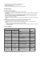
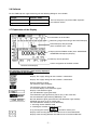
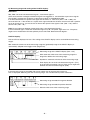
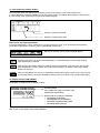
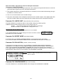
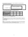
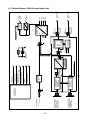
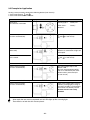
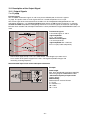
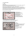
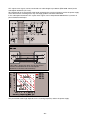
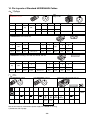
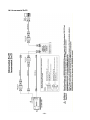
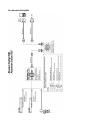
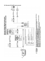
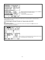
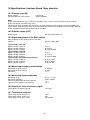
Fig 1: Connecting the PWM 8 in the position control loop of a machine tool controlled by TNC
In order to correctly judge the problems in a machine tool controlled by TNC, fundamental knowledge of the
machine tool and its drives as well as their interaction with the measuring systems is required.
Inexpert handling may cause considerable damage and personal injury.
HEIDENHAIN is not liable for any damage or personal injury caused directly or indirectly or by improper use
or incorrect operation.
Warning: Do not change any parameters or encoder voltages at the PWM while the machine tool is
moving and a PWM is connected.
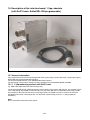
2.2 Description of the PWM 8 Phase Angle Measuring Unit
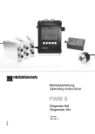
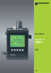
The PWM 8 phase angle measuring unit is a universal measuring unit for inspecting and adjusting
HEIDENHAIN linear and rotary encoders.
The unit is operated by means of 5 soft keys. All values are displayed in a graphics display field. For each of
the different encoder interfaces (11µApp, 1Vpp, TTL and HTL) a separate interface board is required. Each
interface board is equipped with an encoder input (IN) and an encoder output (OUT). The unaltered scanning
signals are available at the encoder output to be fed into e.g. a subsequent electronics. The PWM 8 may
also be connected in series between the measuring system and the subsequent electronics. The axis
functions of the machine tool are not impaired. It is also possible to use the PWM 8 separately for inspecting
and adjusting measuring systems.
2.3 Functions of PWM 8
The main functions of PWM 8 are:
• Display of phase angle and on-to-off ratio
• Display of the scanning frequency
• Measurement of signal amplitude, current consumption and supply voltage of the encoder
• Display of the internal universal counter or the signal periods of a rotary encoder (pulse count)
• Display of reference signal, fault detection signal and counting direction
• Output of the amplified scanning signals (interface board: 11µApp, 1Vpp) or the original scanning signals
(interface board: TTL, HTL) via 3 BNC sockets (e.g. to an oscilloscope)
-5-