1
Operating instructions
Digital Video Sensor DMD - 4
PC-Software V3.xx
Notes for the User
The product and the software or any part thereof must not be reproduced, transferred, converted, or translated into any other language
in any way without prior written approval of NORMA systems
Hard- and Software Development GmbH (called NORMA systems
hereafter). An exception is such documentation and software that
has been explicitly designated and provided as demo version.
NORMA systems provides this manual without explicit and implicit
warranty, including (but not limited to) implicit warranties and conditions regarding the suitability for a specific purpose. NORMA systems will not resume any responsibility for lost profits, lost business
opportunities, lost working time or data, business interruptions, or for
indirect, special, incidental damages or consequential damages of
any kind, even if NORMA systems has been informed that such
damages could occur as consequence of errors in this manual or the
product. The specifications and information contained in this manual
are provided for informational purposes only. NORMA systems may
revise the information contained in this manual at any time without
prior notice.
The contents of this manual must not be interpreted as any obligation
by NORMA systems. NORMA systems reserves the right to reject
any responsibility or claims of recourse for errors and inaccuracies
that may occur in this manual. The same applies to the products and
software described herein.
In this manual, product names are only used for unambiguous designation. Some of the product names mentioned in this manual are
registered trademark respectively subject to copyright of the respective companies. These names cannot be freely used and are subject
to applicable trademark, patent, usage, and design copyright laws.
Contents
-2-
1.0 Installation ............................................................................................... 4
2.0 Technical Data......................................................................................... 5
3.0 Pin Assignment ........................................................................................ 6
4.0 Brief Description ...................................................................................... 8
5.0 Setup structure ........................................................................................ 9
6.0 PC-Dialog .............................................................................................. 10
6.1 Menu ................................................................................................ 11
6.1.1 Symbol bar ............................................................................. 11
- Save / Open File ....................................................................... 11
- Connection via TCP/IP .............................................................. 11
- Data transmission PC Sensor ............................................... 12
- Data transmission Sensor PC ............................................... 13
- Open Channel Setup ................................................................ 13
- Open Channel preview .............................................................. 13
- Timezone Definition ................................................................... 13
- Dome-Tracking .......................................................................... 15
- Copy Setup Data ....................................................................... 16
- Change Password ..................................................................... 16
6.1.2 Service tools ........................................................................... 17
- Sensor options........................................................................... 17
Program Firmware .............................................................. 17
Read Firmwareversion ........................................................ 17
Date/Time............................................................................ 17
Change IP-settings .............................................................. 18
- Load Default .............................................................................. 18
- COM /Using COM ..................................................................... 18
- Change password ...................................................................... 18
- Change language ...................................................................... 18
6.2 Channel setup .................................................................................. 19
6.2.1 Switchbar ................................................................................ 19
- Channel switch .......................................................................... 19
- Timezone ................................................................................... 19
- Area switch ................................................................................ 19
- Detail Setup ............................................................................... 19
6.2.2 Editor ...................................................................................... 20
- Define / Delete area ................................................................... 20
- Define / Delete polygon ............................................................. 20
- Set all cells ................................................................................ 20
- Delete current area .................................................................... 20
- Show / Hide area display ........................................................... 20
- Show all areas .......................................................................... 21
6.2.3 Picture control ......................................................................... 21
- Load current single picture ........................................................ 21
- Start/Pause/Stop picturestream ................................................. 21
Contents
-36.2.4 Info bar .................................................................................... 21
- Show / Hide picture info ............................................................. 21
- Show recognized objects ........................................................... 21
- Show all activated cells ............................................................. 21
6.2.5 Area parameters ..................................................................... 22
- Areamode ................................................................................... 22
Number of cells ..................................................................... 22
Maximum/Minimum number .................................................. 22
Sensitivity .............................................................................. 22
Resettime .............................................................................. 22
- Object detection.......................................................................... 23
Objectvolume ........................................................................ 23
Objectmaximum/-minimum .................................................... 23
Standard ................................................................................ 23
- Perspective ................................................................................. 24
Background / Foreground ...................................................... 24
Perspective............................................................................ 24
6.3 Detail-Setup .................................................................................... 25
6.3.1 Camera options...................................................................... 25
- Channel active ........................................................................... 25
- Camera text ............................................................................... 25
- Relay functions .......................................................................... 26
- Global contact............................................................................ 26
6.3.2 Area Options .......................................................................... 26
- Operation mode ......................................................................... 26
- Timer ......................................................................................... 26
- Switch relay ............................................................................... 27
- Reference area .......................................................................... 27
- External contact ......................................................................... 27
- Direction .................................................................................... 27
- People recognition ..................................................................... 27
6.3.3 Alarm (strings)........................................................................ 28
6.3.4 Sabotage................................................................................ 29
6.3.5 Logic ...................................................................................... 30
6.3.6 Expert .................................................................................... 31
- Ringbuffer .................................................................................. 31
- Binaryfilter.................................................................................. 31
- Trace ......................................................................................... 31
- Object parameters ..................................................................... 32
- Morphing.................................................................................... 32
- Shadow filter .............................................................................. 32
- Definition people recognition ..................................................... 32
- Definition creating statistic ......................................................... 32
7.0 Appendix................................................................................................ 33
7.1 ASCII-Table ..................................................................................... 33
7.2 Release overview ............................................................................ 34
8.0 Safety instructions ................................................................................. 35
1.0 Installation
-4-
Dear Customer!
Thank you for your decision to use the Digital Video Sensor DMD-4 in your
application.
We ask you to read thoroughly through the brief instructions, so that you can use the
DMD-4 functions in an optimum way for your system.
Before installing the equipment, please read the safety instructions on page 35.
Check the included accessories for completeness:
1 x plug-in power supply 9V DC, 2.0A
2 x mounting brackets with screws for mounting in a 19“ rack
1x CAT5- Crossover Patch cable 2m
1 x 25 pin D-SUB soldering plug with cover and mounting hardware
1 x male / 1x female 9pin D-SUB soldering plug with cover
1 x CD-ROM with installation software
4 x self-adhesive equipment feet
Please contact your dealer directly, if any of the accessories should be missing!
1.0 Installation
1.1 PC Setup Dialog
The PC setup program for the DMD-4 video sensor uses the Windows systems 2000
/XP. The screen resolution should be set to at least 800 × 600 and the number of
colors should be set to True Color.
To install the program from the included CD-ROM, run Setup.exe in the “DMD4” folder. Follow the program instructions and install the DMD-4 setup in the desired folder.
After the installation has been completed, start the program DMD4 via the standard
Windows menu Start Program Files DMD4. The setup program for the DMD-4
will be executed.
The program can be uninstalled via the Windows control panel menu “Software”.
1.2 DMD-4
Please connect the video signal of the video cameras to the BNC inputs 1 through 4.
By using the loop-through-Video outputs please and connect the outputs to the monitors, camera switches, etc.
After connecting the power supply the blue symbol “Power LED” lights up.
3-5 seconds after the sensor is initialized (the yellow LED is flashing) and ready for
operation.
To configure the DMD-4, connect the Ethernet interface of the sensor to the LAN port
of a PC or a laptop. Use the included crossover-cable for that purpose.
Important:
If you connect the DMD to a network hub/switch please use a 1:1-patch cable!
After starting the PC setup program, you can setup the DMD-4.
2.0 Technical Data
-5-
2.0 Technical Data
Hardware:
Videosignale:
4 Video inputs, 1 Vp-p, 75 Ohm,
with loop-through output
Termination manually switchable
Sensor cells:
4 areas with over 6000 cells for
each camera
8 scans/sec. each camera
Interfaces:
RS232
RS422/RS485 (galvanic separation)
10/100Mbit Ethernet
6 inputs (4x channel, global, DSTswitch); passive protected
6x relay outputs ( 4x alarm, global,
sabotage)
6 status-LEDs
Programm setup-memory:
Firmware- and setup programming
via Ethernet (RS232 optional)
Integrated realtime clock, buffered
Housing:
19”-plug-in unit, 1 HE,
Color: RAL 7037 , powder-coated
Power supply:
External, 9... 12V DC / min. 1000mA
Software:
PC setup via ethernet interface,
storing and downloading of parameters, password protection
Transmission of camera picture to
PC-setup program for positioning of
sensor areas
4 freely configurable sensor areas
per camera with a resolution of 6480
cells
Object recognition up to 32 objects/camera and object tracking
Analysis with perspective settings
Dome Tracking: When detecting an
object the sensor automatically calls
presets of dome cameras
Recognition / alarm notification of
sabotage events
Misc. filter function for detection of
movements and for reduction of
weather-dependent influences
Integrated week-timer with a resolution in steps of 15-minutes; 4 time
zones programmable with calendar
function
Selection for day/night settings via
external contact
Logical combination of sensor
areas, alarm inputs and timer
Triggering of one relay contact per
camera and individual programming
of serial command sequences for
each area
Live picture transmission and
display of analysis data on PC setup
program.
3.0 Pin Assignment
-6-
3.0 Pin assignment
Front side:
LED´s:
Power:
Control:
1:
2:
3:
4:
Power supply
Operation mode
Alarm channel 1
-“2
-“3
-“4
Rear side:
Assignment:
RS485/ RS422 9-pol D-SUB female connector
1
RS422 RxD/A (+) ; RS485 A
2
RS422 RxD/B (-) ; RS485 B
3
RS422 TxD/A (+)
4
RS422 TxD/B (-)
5
GND
6
Reserved
7
Reserved
8
Reserved
9
Reserved
RS232 9-pol D-SUB male connector
1
nc
2
RXD
3
TXD
4
nc
5
GND
6
nc
7
RTS
8
CTS
9
nc
Using port as RS485:
External Bridge between Pin1 + Pin3,
and Pin2 + Pin4
Termination resistor (Input; Pin 1+2):
Open the unit and change the jumper:
Termination
ON plugged
(Default)
Termination
OFF open
D-Sub
plug
IL 3122E
Null-Modem - cable assignment
PC
sensor :
TxD Pin 3 ------------------ Pin 2 RxD
RxD Pin 2 ------------------ Pin 3 TxD
GND Pin 5 ------------------ Pin 5 GND
RTS Pin 7 ------------------ Pin 8 CTS
CTS Pin 8 ------------------ Pin 7 RTS
3.0 Pin Assignment
-7-
Ethernet RJ45-plug 10BaseT/100BaseTX
1
Rx +
2
Rx 3
Tx +
4
nc
5
nc
6
Tx –
7
nc
8
nc
Alarm / Relais 25-pol D-SUB female connector
1
External alarm input 1 Channel 1
2
External alarm input 2 Channel 2
3
External alarm input 3 Channel 3
4
External alarm input 4 Channel 4
5
External alarm input 5 - DST switch
6
External alarm input 6 - Global contact
7
GND
8
GND
9
GND
10
GND
11
GND
12
GND
13
GND
14
RELAY 1
contact
15
RELAY 1
make contact
16
RELAY 2
contact
17
RELAY 2
make contact
18
RELAY 3
contact
19
RELAY 3
make contact
20
RELAY 4
contact
21
RELAY 4
make contact
22
RELAY 5
contact
sabotage relay contact
23
RELAY 5
make contact
24
RELAY 6
contact
global relay contact
25
RELAY 6
make contact
nc: not connected
DC socket 2,1mm
Center contact positive:
+9...12V/ 1000mA
Note: Only galvanically isolated, stabilized power supplies with
+9 ...+12 V may be connected to the unit!
4.0 Brief Description
-8-
4.0 Brief Description
DMD-4 is a digital video sensor for simultaneous monitoring of four camera signals
(channels) for indoor and outdoor applications.
The sensor is also capable of detecting video picture changes under difficult light
conditions.
The PC setup program interface of the DMD-4 allows comfortable setting of all sensor parameters.
First, the respective camera picture has to be transmitted from DMD-4 to the PC
and displayed in an editor window. Each channel can be configured for four time
zones. Using the PCs mouse you can now define four sensor areas per channel according to the local conditions.
For each sensor area there are extensive setting possibilities such as number of
sensor cells, sensitivity, perspective, reset timer or alarm strings.
For recognition of sabotage events like spraying or other manipulations you can adjust a special sabotage analysis.
In case of a detected object the sensor can control a dome camera regarding to the
centre of gravity („Dome tracking‟). You can choose a protocol from a list of many
well known manufactures.
Having programmed all setup-parameters, these are transferred from the PC to the
DMD-4. The sensor now operates with the new parameters independently from the
PC.
The setup data can also be stored on hard disk/diskette. Thus it is possible to transfer standardized settings without great effort to several sensors. In case of failure,
the service engineer can determine whether the setup has been changed by unauthorized persons and he can directly reestablish the original configuration.
The camera pictures including the defined sensor areas can be stored in graphic
format (*.jpg or *.bmp) for documentation purposes.
DMD-4 uses state-of-the-art Flash technology:
Upgrading the operating software (firmware) can be performed without opening the
equipment; upgrades can be loaded via PC or laptop via the RS232 interface.
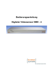
In the following sections the setup functions, the individual sensor parameters and
their settings are briefly described. The diagram on the following page shows an
overview of the parameters that can be configured in the menu.
5.0 Setup structure
-95.0 Setup structure
Timezone 1...4
Camera inputs 1...4
Sensor area 1...4
Day / Hour timer
Relay resettimer
1..6480 cells
External switch of
daylight saving time
Retriggering the relay
for new trigger
Min./Max. number of
cells
Definition
External input NO/NC
Filter functions
Logical combination
of main area
Definition
Videofail / Sabotage
Alarm Resettimer
Object recognition /
perspective
Switching Channel- /
global relay
External
contact
Definition
Dome - Tracking
Sensitivity
Object Definition
Reference area
Statistical functions
Timeout after exceeding max. number
Number of events until
Alarm triggering
Red and green area:
Preferred directions
Definition of
Alarmstrings
6.0 PC - Dialog
- 10 -
The chart on the previous page shows, that the different functions of the DMD-4 are
linked to the spheres of timezone, channel and area. These three spheres have the
following hierarchical structure:
Timezone Channel Area.
Each of the timezones has four channels, each with four sensor areas. Therefore all
parameters assigned to a timezone are valid for all subordinate channels and the
corresponding sensor areas, too.
In the next chapter the structure of the PC dialog and the function of all parameters are
described.
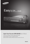
6.0 PC Dialog
After starting the program, the main window appears on the monitor.
Via the upper menu bar all sub menus for communication and global settings are
reachable.
Under them an editor appears with the most important channel settings. The parameters can be directly adjusted in this window.
Menu
View
Editor
Standard settings (default values) are defined for all four camera channels.
All “switches” and input fields feature help texts, so that the user can quickly become
acquainted with the setup procedures.
The following pages describe the individual setup functions:
6.1. Menu
- 11 -
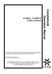
6.1 Menu
Service functions
Program information
Menu bar
Symbol bar
The menu is divided in two areas: The menu bar includes functions via pull-down
menus, who are reachable via buttons of the symbol bar too, and further configuration
tools (service functions) and viewing options.
6.1.1 Symbol bar:
Provides direct access to all important functions:
Save / Open File:
Saves / Loads a setup configuration previously stored on harddisk or diskette. This allows, for example, programming the sensors with standardized settings.
Connection via TCP / IP:
Opens a submenu for data transmission via TCP /
IP or close a connection:
In the address list you can manage IP-addresses
of many sensor units.
For open a connection select the desired name
and click to the ‚Connect„- Button.
If the connection has been successfully established, a message appears and the dialog box is
automatically closed.
The termination of a established connection can be
done via the ‚Disconnect„- Button.
The connection to the DMD-4 can establish via Lan or for remote maintenance over
the internet.
LAN:
In the LAN the connection to the DMD is defined by IP-address a Port-No. (Delivery
state: IP: 192.168.1.254; Port 81). The PC or Laptop must have an address in the
same number range (e.g. PC: 192.168.1.51).
Mouse-clicking on the PC-Info button displays the actual IP-address. The IP-address
can be changed in the windows-menu (Network->LAN->Settings->Internet protocol).
Subnet mask is 255.255.255.0.
When it`s not possible to change the IP-Address then its necessary to change the address of the DMD-4 (s. 6.1.2, sensor options).
Remote maintenance
To configure the DMD-4 via remote maintenance the DMD-4 must be connected to a
router who has access to the internet. Normally the router is registered to a Nameserver like DynDNS.org, ZoneEdit.com, NoIP.com e. c.. In our example the identifier is
ecompany.dyndns.info.
6.1. Menu
- 12 -
The field Nameserver is filled out with the identifier, Port-No is the number who is registered under Port-Forwarding in the router menu.
Port-Forwarding means that data packages from the internet with a specified Port-No
are transferred to a specified IP-address in the LAN.
Example:
The DMD has the IP 192.168.1.71, Port-No. 81. The route menu is so configured, that
all incoming data packages with the Port-No. 90 are transferred to the DMD-4 address.
Data transmission PC Sensor:
Opens a dialog box for controlling the transfer of setup data from PC to the unit:
Send Camera-Setup: Programs the sensor with the parameters that have been configured in the PC setup. This
irrevocably overwrites the setup data in the
DMD-4. Use the camera selection buttons (appears in
red) to select the channel that has to be transferred.
If the connection has been successfully established, a
progress indicator bar shows the progress of the data
transfer. When the transfer has been completed, the dialog box is automatically closed.
Send entire Setup: Programs the sensor with the parameters of all 4 cameras inclusive the global settings.
The data transmission is performed as described in “Send
Camera-Setup”.
In case of errors during data transmission the status line displays error messages:
If, for example, the connection cannot be established, the connection settings must be
checked.
If an error occurs during data transmission, the process must be repeated.
.. Delete Statistic: The sensor analyses each channel regarding his regular movements over the whole picture area. Over a longer time period the individual, statistical
results will be collected and stored in an internal memory. After a fundamental change
of settings or after turning of the camera this clear function of the statistic values is
recommend.
6.1. Menu
- 13 -
Data transmission Sensor PC:
Opens a window for controlling the data transfer from DMD-4 to the PC.
Load Camera-Setup:
Loads the sensor configuration of the desired camera (red
button). This irrevocably overwrites the setup data of the
PC. The data transmission is performed as described in
“Send Camera-Setup”.
Load entire setup:
Load the setup configuration of all four channels and the
global settings of the DMD-4.
The data transmission is performed as described in “Send
Camera-Setup”.
Open Channel Setup:
Opens in the viewing window below for setting all basic parameters of the channels
(see page19).
Open Channel-preview:
Opens a quad-view for all 4 channels, who are refreshed sequencial with the live pictures. By mouse-clicking to one of the windows you can call up directly the regarding
Channel-Setup.
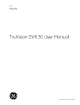
Time zone definition:
Each channel of the DMD-4 is equipped with a total of four time zones. Different sensor areas can be placed for each of these zones. Therefore four completely independent day and week programs are editable for each channel.
First of all the zone to be defined
is selected with the camera- and
timezone-buttons:
The timezone 1 is always displayed in the upper half, one of
timezone 2-4 in the lower half of
the window. With a mouse click or
Drag & Draw (drag the mouse by
pressed left button) you can define
the active time for timezone 1
(shown as red blocks). In the left
image there is an example for different shopping times. All the periods of the closed store are registered in timezone 1 as shown on
the left side.
6.1. Menu
- 14 -
The blue blocks indicate an inactive time area. Time arreas, which are overlapped by
two or more timezones are colored yellow.
The priority within the four time zones is defined as going down from zone 1 to zone 4.
Example: If zone 1 and zone 3 overlap, only zone 1 is active. If you only need to work
with one time zone than there is no need to program all zones:
Marking the hole area (Monday...Sunday , 00:00...24:00 o‘clock) for timezone 1 activates the system for the whole week, 24 hours a day.
Note: The sensor is disabled if not one of the 4 timezones is active.
For some calendar days you can define the special zone-function on these days. The
definition of calendar days is independent of any years!
The sensor is equipped with an integrated switching input of daylight saving time
(DST). If the switch is activated (interprete DST switch) the sensor automatically
switches – in case the contact is closed – between the timezones as follows:
When the contact is closed, the unit regards - in according to the time definition – only
the settings of timezone 2 or 4. On the other hand (contact is open) only the parameters of zone 1 or 3 are possible.
Example: A day- and night program has to be defined for Monday to Friday respectively Saturday and Sunday each. For that purpose the whole time area from Monday to
Friday is activated in zone 1 + 2, the same area of Saturday and Sunday in zone 3 +4.
This result that Mo.-Fr. the unit is defined by timezone 1 during the day, in the night by
the settings of zone 2. On the weekend (Saturday, Sunday) the sensor switches between timezone 3 (during the day) and timezone 4 (night)..
By using the DST switch the priority is also valid: If the active areas of time zone 2 and
4 are overlapping to each other, in the overlapping area only the settings of time zone
2 are valid.
6.1. Menu
- 15 -
Dome-Tracking:
Using the mode Dome tracking the sensor controls the presets of a P&T head regarding to the coordinates of an object, which has been detected. According to different
camera-types and –protocols the sensor has to be programmed with a special ‚DomeFirmware„ (see Sensor options). An information about the activated protocol appears
by using the ‚Dome-Typ‟-button (The default protocol is ‚Panasonic„).
The individual setting of presets, dome address and home position can be adjusted for
each channel in the following dialog box:
First of all the Dome tracking mode has to be activated (‚Tracking On„) and the dome
address has to be entered. Optionally you can define a home position: After expiration
of ‚time„ since the last preset command the sensor will call up this preset number
automatically. Note: Activating the Dome tracking mode automatically activate the
RS485 interface (s.p. 28).
All preset numbers can be defined for each cell within a 16x16 grid:
Using the numeric pad buttons of ‚preset„ the actual preset number in the position field
is entered. Then the mouse cursor is positioned on a grid cell and by clicking the left
mouse button the cell is defined by this number. Deleting cells is performed as follows:
Define the actual position as ‚Delete„ (‚Delete„ button) and click on the desired cell.
When the mouse cursor is positioned on a cell, that has been already defined, the preset number of ‚position„- field will be overwritten by the cell-preset by clicking the right
button.
To control defined presets in according to the picture areas of the reference camera
you can activate ‚Dome Test ON‘ using the connected sensor/dome:
Clicking on a defined cell or using the numeric pad on the left and the ‚Select„ button
the sensor will send the command for the desired preset number. If required you can
manually adjust the settings of the preset (P/T, zoom, focus, iris).
Please use the button ‚Save„ to store the new preset settings in the dome.
The window of ‚Status„ shows the last commands.
6.1. Menu
- 16 -
IMPORTANT: The following conditions have to be performed for dome tracking:
The centre of gravity of the object is within an area with ‚object
mode/perspective„;The channel is activated; The object size is between minimum
and maximum number of cells.
Copy Setup Data:
This option allows the copying of
sensor settings within the channels or
timezones:
In the left example all data of timezone
1 will be copied to timezone 3+4 over
all 4 channels, regardless of the
„Camera‟- configuration.
However, by copying Camera settings
or Alarm strings the source/target-configuration of timezone is important:
According to the upper timezone definition all camera data /alarm strings of camera 2,
timezone 1 will be copied to timezone 3 of camera 3 and 4.
Therefore the user does not have to program the whole setup anew if the parameters
of the sensor areas only differ marginally.
Change Password:
The setup data is protected from unauthorized access by a password. A data transmission can only be executed successfully if the password of sensor and PC program
is the same. It is recommended to alter the password immediately after the first start of
the setup program.
NOTE:
The password can only be changed when the sensor is connected to the PC interface
and has a maximum length of 10 characters and is case-sensitive!
The password can be changed in the following dialog box:
Old Password: Enter the current password of the DMD.
The pre-configured password is “video”.
New Password: Enter the new password.
Confirm Password: Repeat and confirm the new
password.
The new password is accepted by clicking “Change password”.
Attention:
When the password has been lost, please contact your
dealer.
6.1. Menu
- 17 -
Service tools:
Opens a pull-down menu for controlling the following submenus:
Sensor options:
Program Firmware:
The sensor is Flash-programmable. This
means that the firmware can be
transferred to the processors by a
PC. Changing EPROMs and thus
opening the device is not required.
When the firmware is changed, for example during a functional upgrade or
with special software, the firmware is
loaded to the DMD-4 via this dialog
box.
The sensor is equipped with 2 flash
memories: Main and Dome.
By clicking the corresponding button, the
Windows “Open File” dialog box is
opened and you can select the file (*.bin)
to be programmed. Subsequently, the
transfer to the sensor is done and a percent display indicates the progress of the
process.
After successful transfer, the message “ Firmware programmed” is displayed on the
right hand of the button.
In case of errors during data transmission the status line at the bottom displays corresponding error messages.
Read Firmwareversion:
The actual firmware versions and the date of each last programming action are displayed. By pressing the „version‟ button the current data of the DMD-4 are displayed.
An overview of the current releases is shown on Appendix (page 34).
Date / Time:
By clicking the button „Send Date /Time‟ date and time are transferred separately in
order to synchronize the internal clock of the DMD-4 with the system clock of the PC.
You can double check the actual time setting by clicking on ‚Check Date/Time‘.
6.1. Menu
- 18 -
Change IP- settings:
Allows reading out and changing the actual IP-configuration of the sensor.
Notes: Changing of the IP-address will always result a disconnection of the established network connection. If necessary the PC / laptop have to be switched to the new
IP-address. It is recommended documenting the actual IP-configuration.
Load Default:
Restores the default values (restart) of the PC user interface.
ATTENTION: A reset overwrites all current setup settings of the user interface
with default values!
COM:
Allows setting up the configuration-RS232 interface
of the PC (COM1…COM50), to which the sensor is
connected:
The DMD-4 interface is factory-configured as follows:
.. 8 data bits
.. no parity
.. RTS/CTS
.. Baud rate 115.2 kB.
Use COM:
Defines the kind of configuration interface Ethernet (default) or RS232-comport (settings see above). By clicking to point ‚Use COM„ you switch between of using Comport
(a ‚„ appears in front of ‚Use COM„) and the Ethernet ( the ‚„ disappears ).
Change password:
Opens a submenu for changing the actual password setting. You will find further descriptions on page 16.
Change language:
Opens a window for changing the actual language setting of the PC-program.
The setting will be valid after a restart of the PC too.
6.2 Channel setup
- 19 -
6.2 Channel setup
Switchbar
Area parameters
Editor
Info bar
Picture control
6.2.1 Switchbar:
Channel switch:
Switches between setup setting of camera 1...4.
Timezone:
The timezone to be configured is selected with this button.
Area switch: To be able to distinguish the sensor areas from each other via
pull-down menu:
= Mainalarm area
= Prealarm-area 1
= Prealarm-area 2
= Prealarm-area 3
In the example shown above, the setup parameters refer to sensor area 1
of camera channel 1.
Detail-Setup:
By activating an overview of all channel parameters will be displayed (see
description on page 25).
6.2 Channel setup
- 20 -
6.2.2 Editor:
The editor area with the camera picture of the corresponding channel is divided into
6480 parts, called cells. The sensor area is defined by all highlighted blocks of the corresponding color. It is not necessary that all blocks are adjacent to each other. An
overlapping of two or more areas is not allowed.
The editor tool bar provides several functions for the editor display and for positioning
the individual cells:
Define / Delete area:
If a larger area of the sensor area is to be activated or deactivated, this area can be
marked with the mouse:
Position the cursor in the editor, press the left mouse button and
draw a frame around the desired cells by dragging the mouse.
Depending on the sensor area selected, the rectangle is shown
colored. The corresponding function is executed on the marked
area, after releasing the left mouse button.
Deleting cells is performed according to the same principle: The mouse cursor is positioned on an cell and by clicking the right mouse button the rectangle appears black
and after releasing the right button all cells in the defined area are deactivated.
Define / Delete polygon:
The drawing of a polygon allows a quick area definition:
By pressing the left mouse button you define the edges of the polygon. If you have keep pressed the left mouse button for 2
seconds: All cells inside of the polygon turn in the area colour
and are activated.
Deleting cells is performed according via the right button: the
edges of the deleting polygon are defined by pressing the right
mouse button. After definition of all edges you have to press the right button for approx. 2 seconds, and all cells inside of the polygon will be cleared.
Set all cells:
Activates all cells from the current sensor area. If some cells also defined by another
area, only the remained cells will be activated.
Delete current area:
Deletes all cells from the current sensor area.
Show / Hide area display:
Switches between the camera image with or without displayed area in order to check
the right overlaying of picture and cells.
Show all areas: For easier positioning it is possible to display all areas in the
editor. The area that has been selected by the area switch is edited.
6.2 Channel setup
- 21 -
6.2.3 Picture control:
For an exact overlay of the defined area the picture of the corresponding channel has
to be displayed. You can receive a single picture from the connected sensor.
Furthermore you can get a continuous live stream of up to 6-7 pictures / second, in order to control the analysis of the sensor. Different display functions of the internal sensor information are available and are descript on chapter 6.2.4 .
Load current single picture:
The old picture display will be overwritten by a new picture.
Start picture stream:
The displaying of current live pictures will be started.
Notes: For changing of parameter settings it is recommend to stop the picture stream
first.
Pause picture stream
The displaying of picture stream will be paused.
Stop picture stream
The continuous picture stream will be stopped, in the editor field remains the last received picture.
Compression
Change the compression rate of the transmitted picture. To enhance the picture rate
while connected to the DMD over DSL, it´s recommended enhancing the picture compression.
6.2.4 Info bar:
By viewing the picture stream there are some tools to inform the installer about the internal effect of the DMD:
Show / Hide picture info:
Displays information about size, date in the left, upper side of the picture.
Show recognized objects
The sensor will mark objects, who correspond to the defined object size, as a green
frame, additional with a motion vector. In case of an alarm the state will be displayed
above of the frame.
Show all activated cells:
Alterations in the camera picture are visible foe each individual cells. The sensor will
mark the cells as orange points.
6.2 Channel setup
- 22 -
6.2.5 Area parameters:
Up to 3 different operation modes can be defined for each area. The displays of parameters switch in according to the desired function. The meaning of each mode and
the corresponding functions are described on the following pages:
Areamode
Every sensor area has parameters that can be edited independently from the other areas in this dialog box. A selection of
fundamental parameters is shown on the right hand of the edit
field:
Number of cells: The display of activated cells (here 1325) is
only an information and will not be stored in the sensor.
Max.: A change of the picture is only evaluated as an alarm, if
not more than the set cells detect a movement (here: 552).
The desired number of cells is set by means of the slide control
(the value appears absolute and as percentage).
Note: The sensor area is deactivated at the “Max” setting (=0).
Tip: You can change the slider-value in single steps by using the arrow keys of your
keyboard.
If more than the set cells detect a movement, the timer “Max break” (see page 26) is
activated. This function prevents triggering for brief changes of the light conditions etc.
Min.: The alarm is only triggered if at least the number of set cells detects a change in
the sensor area. Thus, too small and therefore irrelevant objects do not cause an
alarm.
Note: Min=0 is the same as Min=1, which means that at least in one cell a movement
has to be detected before the area is triggered.
Sensitivity: Sets the sensitivity for all marked cells of the sensor area. The higher the
value set (1-10), the higher is the sensitivity of the cells.
“Sensitivity” defines the trigger‟s sensitivity of the time interval.
Reset time: Is started when the sensor area initiates an alarm.
After expiration the alarm of the sensor area is reset. This includes: The display of the
area, the internal linking (see “Logic” on page 30) and the transmission of the serial
alarm strings („Alarm OFF strings‟, see page 28) .
NOTE: The alarm relay – if activated – is only reset after expiration of the relay energizing time set under “Camera options” .
6.2 Channel setup
- 23 -
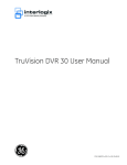
Object detection
In the object mode all detected, contiguous cells are combined as one or more objects
according to their position to each other. The object size and not the total number of
activated cells will be compared to the defined number of maximum/minimum cells. Up
to 32 independent objects can be detected within the defined area simultaneously. The
following illustration shows the object detection mode:
Objectvolume: Number of the cells that are enclosed by the
rectangle in the edit field (in the example on the left side 364).
The number is only information to estimate the object size.
This parameter has no further influence and will not be stored
in the sensor unit.
The definition of the object size can only be set by Objectmaximum/Objectminimum, described next.
Objectmaximum / Objectminimum: An object within the defined area is only evaluated as an alarm, if the number of detected cells is between the objectminimum and objectmaximum (in the example between 109 and 910 cells).
Exceeding the objectmaximum will start the timer ‚Max.
Break„, if selected.
Sensitivity: The entry of the parameter is performed as described in Area Mode.
Standard: According to the object volume of the rectangle the values of max. – and
min. object volume will be set to 250 per cent and 29 per cent respectively. This value
is a basic parameter based on operating experiences. However the installer has to find
out the optimal values according to the real scenery.
People recognition: The meaning and possible parameters are described in DetailSetup (Area options and Expert).
6.2 Channel setup
- 24 -
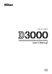
Perspective
The sensor is detecting in addition to the object mode according to perspective parameters. Two rectangles appear on the edit area for defining the position of the foreground and the background.
Important: The number for the object size in the foreground / background (example of
image: foreground 364, background 66) is only information to estimate the desired object size. The definition of the object size is effected by the parameters Maximum/Minimum on the right hand of the edit:
Background: An object on the background position (Definition: center of the rectangle) triggers only an alarm if the number of activated cells is in the range of object
minimum and object maximum (In the example between 19 and 165). The same range
is valid for objects that are farther away. For more information see object foreground.
The sensitivity is valid for all cells that are on the background position or farther.
Foreground: An object at the fore position (Definition: The
centre of the fore rectangle) triggers only an alarm if the
number of activated cells is in the range of object minimum
and object maximum (In the example between 109 and
910). The same range is valid for objects that are positioned
nearer. The sensitivity is valid for all cells that are on the
foreground position or nearer.
Important note: For all object positions between fore- and
background the sensor calculates automatically the intermediate values of maximum, minimum and sensitivity.
Standard: According to the object volume of the rectangle
the values of max. – and min. object volume will be set to
250 per cent and 29 per cent respectively.
Perspective: There are two kinds of perspective-definitions:
Horizontal: An object, that is moving at the same image column, appears smaller in the upper rows (background) than
in the lower rows (foreground). This is typical for camera
configurations outdoors.
Vertical: An object, moving at the same image row, appears
smaller (bigger) on the left side than on the right side, for instance a camera perspective along a wall.
People recognition: The meaning and possible parameters are described in DetailSetup (Area options and Expert).
6.3 Detail-Setup
- 25 -
6.3 Detail Setup:
For each of the four channels special parameters can be set. The menu is devided in
different areas. The validity of the current parameter is green displayed in the upper
right edge ‚valid„.
Via the switch buttons of timezone and cameras all important seto parameters can be
directly adjusted. Via the copy button you can copy the parameters between channels
and timezones (see description on page16).
The following pages describe the function of the submenus:
6.3.1 Cameraoptions:
Channel active: Allows quick activation/deactivation of the channel, for example
when maintenance works in the viewing range of the camera are not supposed to
trigger the sensor or to be detected as sabotage.
Channel text: The text can be edited directly in order to identify the meaning of the
camera. This identifier appears in the Channel setup.
6.3 Detail-Setup
- 26 -
Relay functions:
Defines the settings of the channel- and global relay. The definitions Retrigger and Resettime are valid for both relays.
Retrigger relay: If another alarm occurs during the time the relay is energized, the time
is automatically prolonged by the configured time.
Watchdog: (De-) activate the watchdog function (relay is normal closed) of the channel
relay.
Resettime: Defines the time the relay is in energized state. The maximum time is 120
seconds = 2 minutes
NOTE: The selected time is equal to the auto reset time for the LED display.
Global relay is NC: If activated, the watchdog function of the global relay is on.
.
.. Global Input: The sensor is equipped with an external global input, which can be
considered by each channel separately :
Interpret contact: If activated the contact state has to be according to the global contact definition (see next parameter).
Contact is Normally Closed: Subordinate channel can be linked to this input.
When the channel parameter „Interpret contact‘ is activated, the channel only triggers if
a.) the global input has been closed (checkbox „Contact is NC‟ is active)
b.) the global input is open (checkbox „Contact is NC‟ is not active).
6.3.2 Areaoptions:
All important parameters of the main area and the 3
prealarm areas are listed in this submenu. You can switch
the setting between the areas by clicking on the upper buttons.
..Operationmode:
Defines the kind of operation mode (see description ‚Area
parameters„ on page 22).
..Timer:
Defines the following timer:
Resettime:
Timer is started when the sensor area initiates an alarm.
After expiration the alarm of the sensor area is reset. This
includes: The internal linking (see “Logic” on page 30) and
the transmitting of the serial alarm strings („Alarm OFF
strings‟, see page 28).
NOTE: The channel relay will only be
relay energizing time set under “Cameraoptions”.
reset
after
expiration
of
the
6.3 Detail-Setup
- 27 -
Max. Break: Time within the sensor area stays inactive after exceeding the maximum
permissible number of triggered cells (Min./Max.).
Prevents repeatedly triggering after turning on room lights etc.
Switch relay: The relay of the corresponding camera channel is energized for an
alarm of the sensor area.
Note: If the area is only to trigger a pre-alarm, this function usually must be deactivated.
.. Global Relay: The global relay is energized for an alarm of the sensor area. The
function of this relay is a logical OR-function of all areas, who switch according to this
function the global relay.
.. Reference area: If an area is defined as reference area, it is evaluated with priority:
In any case, the reference area is analyzed before the other area of the channel. Where
a reference area is defined to suppress influences that make an effect to the whole picture e.g. weather influence like clouds.
External contact:
Each channel is equipped with an external input, which can be taken into account for
alarm processing.
Interpret contact:
When the option is activated, the sensor area only triggers if the external input has been
connected in the manner (normally open or normally closed) that has been defined as
„Contact is NC‟ .The external input allows several applications:
Controlling the sensor area by an automatic timer, additional combination with an IR
alarm, manual control (gate keeper) etc.
Contact is NC:
When this area parameter is activated, the sensor area only triggers if
b.) the external input has been closed (checkbox „Contact is NC‟ is active)
c.) the external input is open (checkbox „Contact is NC‟ is not active).
.. Direction: Configuring eight possible direction preferences, objects triggers only an
alarm those movement is in the selected direction. Movement in the opposite direction
will not trigger any alarms. If no direction is selected (all arrow buttons appears with red
frame), no direction filter is active and all movements could cause an alarm.
People recognition:
Each detected object of the area can be analyzed concerning to a contour of a person.
This mode should only be activated for the limited purpose of people recognition. Other
objects would not cause any alarms. The definition of the people recognition can be
done for each channel and is described in menu Expert (see page 32),
6.3 Detail-Setup
- 28 -
6.3.3 Alarm:
Allows the configuration and entry of a character string (alarm string) that is transmitted
via the RS232/RS422- or Ethernet interface of the DMD-4 to peripheral devices like a
switch or recording system
Alarm strings can be defined for the main
area and for the three prealarm areas of a
camera channel. By clicking to the buttons
Mainalarm and Prealarms you can switch between the different editor menus.
The sensor can transmit one data string after
alarm activation anf after Resettime has expired. Thus the peripheral devices connected
can be controlled differently for alarm activation and expiration of the Alarm Resettime.
Example: For an alarm a matrix-output switch
to a full picture of the corresponding camera.
After the expiration of the Auto Reset time, the sensor will send a command for quad
view.
The maximum string length is 40 characters. The characters are input in hexadecimal
notation, i. e. only characters from 0…9 and A…F are allowed.
This type of character-coding allows transmission of any text and control commands.
Important: The string is only transmitted when the box for ON respectively OFF is
checked. In the Prealarm menu the checkboxes define these prealarms, who have to
send out the defined strings.
The following example shows a character string that has been defined for sending an
alarm text:
Code (HEX)
Character
02
STX
41
'A'
6C
'l'
61
'a'
72
'r'
6D
'm'
20
' '
54
'T'
6F
'o'
72
'r'
20
' '
31 03
'1' ETX
In the submenu Alarm interface at least one of the three possible interfaces has to be
activated. The menu to define the serial settings appears after clicking on ‚Setup„ :
IMPORTANT:
If Dome-Tracking (view S.15) is active
the settings of RS422/RS485 should
be in accordance with the data format
of the according dome protocol.
In standby mode the RS232 settings
of the DMD-4 are adjusted to the data
communication between PC and
Sensor (see ‚Use COM„ on page 18).
In the case of sending alarm strings
to peripheral devices the sensor
automatically switches to the interface settings which have been defined in this menu.
After transmitting the alarm string the DMD-4 automatically restores the original interface parameters.
Using the LAN interface the IP address and the port number of the target unit has to be
defined. In case of an alarm the sensor will establish an IP connection, and will send the
alarm strings. After sending the connection will be closed.
6.3 Detail-Setup
- 29 -
6.3.4 Sabotage:
Up to 3 different kinds of sabotage detections can be defined for each of the four
channels:
Video fail
When a video signal fails – channel
is activated (see Camera Tool Bar),
no video signal has been applied to
the input – the LED of the corresponding channel flashes on the
front side of the device.
Videosignallevel
When this function is activated an
arithmetic reference value (for all
picture intensities within the defined
green area prealarm3) over 5 minutes will be calculated in order to
take account of slow luminance alteration, like twilight, common changing of weather conditions.
At the same time an arithmetic mean is registered over a short time of 10 seconds. Intensity changes by moving objects effects no alarm. A durable change like covering of
the camera objective or a lasting local variation in the camera picture causes a sabotage alarm. In this case after 5-10 seconds an alarm is occurred.
The alarm threshold can be adjusted in 9 steps. In case of outdoor areas (short-term intensity changes by sun or clouds) it is recommended to set the threshold to higher signal deviation.
Signalcharacteristic
By activating of this function a reference value will be initiated, however as an average
difference of the arithmetic mean. The calculation is done for the distribution of all intensities within the camera picture. This feature is especially recommended for highcontrast images, because sabotage by paint-spraying to the camera objective or distorting of the camera-view effects a bad-focused and low-contrast image in the most cases.
The reference value is adapted dynamically. The notes for alarm activating and the
alarm threshold are performed as described in „Videosignallevel‟.
A sabotage alarm can be indicated by energizing the sabotage relay and / or by sending
a serial sabotage string (definition for each channel; character entry and interface definition as described in „Alarm‟ on page 28).
The relay is energized as long as the sabotage is detected.
The transmission of the serial string starts with detecting a sabotage and – setting „repeat‟ is activated – each second anew..
6.3 Detail-Setup
- 30 -
6.3.5 Logic:
Each mainalarm area can be logically linked with the channel-own prealarm areas and
the mainalarm areas of the other channels. This results in a higher switch security and
ensures that temporal sequences are detected.
First of all the mainalarm area to
be defined is selected with the
timezone- and channel- buttons.
Afterwards the combination of the
additional areas can be done:
All edit fields, who stands in parallel are together with the defined
area AND connected and constitute a term.
Under it one more term can be
constituted.
If the conditions of one or both
terms are true, the defined area is
triggered.
The bar above the entry fields defines the condition ‚area is triggered„(bar is red), or
‚area is not triggered„(bar appears in grey).
In the example above the mainarea is only triggered,
if the green area prealarm1 is triggered too , or
if the yellow area prealarm3 is triggered too and the blue area prealarm2 is not triggered.
6.3 Detail-Setup
- 31 -
6.3.6 Expert:
The settings of the expert menu are pre-configured for the most typical applications. In
order to adapt the sensor in an optimal way to the real szenary the meaning of the
following parameters are descripted:
Ringbuffer:
The DMD-4 scans the entire video
picture 8 times per second. Thus,
very fast picture changes can be
correctly detected.
If tiny objects move very slowly,
sensors with a measurement of a
fixed, short time interval may not
always trigger correctly between
two video pictures which are to be
compared.
The change in brightness as compared to the time interval is not
large enough to exceed the trigger
sensitivity (see also “sensitivity”,
page 23).
The DMD-4 solves this problem by
an extension of the time interval by
means of an internal circular buffer.
Now slow movements in the picture
can be correctly detected.
The setting of middle / long in connection with changing illuminations can cause
unmeant activations particularly in outdoor applications. Therefore this parameter has to
be set very carefully.
Binaryfilter: Defines the suppression of noise- and fail-influences against to the detecting objects. The function can be set in four steps.
The size of proximate, detected cells grows by increasing this parameter.
In case of great detecting objects at fore- and background (!) the increment of the binaryfilter value is highly recommend!
Trace: The sensor is analysing all current, detected objects regarding to their further
course. The length of the resulted motion vector is a measure for the distance covered.
(Trace). The value of the trace parameter defines, whether a recognized object causes
immediately an alarm (left position, trace is disabled), or after achievement of a minimum trace distance (short, middle, long).
Objects, which are moving predominantly in one direction, can be unambiguously identified. On the other hand, objects that do not move in one direction such as a tree in the
wind cause only a local movement without a significant trace.
Note:
Increasing of the value trace extends the analysing time of the objects and the time until
alarm triggering!
6.3 Detail-Setup
- 32 -
Morphing: If activated, tiny, divided objects will be combined to one object. This
mode is helpful in situation of bad contrast to avoid the fragmentation of an object in
several parts, which would be too small for the minimum object size.
Shadow filter: Blurred objects and shadows will be ignored by the sensor. Influences of clouds or non-sharp-cut spiders on the lens will be minimized.
Number of detections: Changes of the sensor area that – according to the configured parameters – must cause an alarm has to be detected n times immediately following each other (n = parameter value) before the alarm becomes active. Thus, nonrecurring events such as light reflections can be excluded.
Note:
If an object enters the alarm area an additional delay (n x 1/8 second) occurs before the
alarm is triggered.
Max. Object Analysis: If activated, the parameter ‚maximum object size„ (area parameters) would be utilized. In many cases exceeding of the defined maximum cells is
a global changing over the whole picture area, which shouldn‟t cause any alarm for a
short time (see ‚Max. Break„ on page 26).
The disabling of this parameter means that all objects over the minimum number will activate the area irrespective of the defined maximum.
People recognition: The analysis of people is based on an idealized contour of an
upper part of a human body. With the sliding controller of People outline the user can
adjust the matching by percentage (typically between 35 and 60%).
Against the recommend middle setting of the Contrast parameter this setting can be set
to foggy in case of bad-contrast situations, or to sharp in applications with sharp-cut objects and well-lighted scene.
Create statistic: The sensor can make a dynamic statistical census of each single
cell, in order to consider periodical noises, interferences, and to eliminate these influences against singular events.
The mode is qualified for outdoor applications, in which only few changing and objects
could be detected.
The census starts after a reset new.
Disturbance: Controller to set the size of the disturbance in relation to the min.
size of the object. Default is 50%. Is the size of the disturbances in the alarm area huge
(Bushes, trees), then it`s advisable to increase the value. When snow or heavy rain
appears in the picture, it`s not necessary to change the value.
Statistic reduction: Define the time, where the statistic decreases to zero after no
disturbance is recognized. This parameter should only be changed (decreased), when
public areas with a lot of traffic are monitored.
7.0 Appendix
- 33 -
7.0 Appendix
7.1 ASCII-Table:
character
<NUL>
<SOH>
<STX>
<ETX>
<EOT>
<ENQ>
<ACK>
<BEL>
<BS>
<HAT>
<LF>
<VT>
<FF>
<CR>
<SO>
<SI>
<DLE>
<DC1>
<DC2>
<DC3>
<DC4>
<NAK>
<SYN>
<ETB>
<CAN>
<EM>
<SUB>
<ESC>
<FS>
<GS>
<RS>
<US>
<Space>
!
``
#
$
%
&
`
(
)
*
HEX
00
01
02
03
04
05
06
07
08
09
0A
0B
0C
0D
0E
0F
10
11
12
13
14
15
16
17
18
19
1A
1B
1C
1D
1E
1F
20
21
22
23
24
25
26
27
28
29
2A
character HEX
+
2B
„
2C
2D
.
2E
/
2F
0
30
1
31
2
32
3
33
4
34
5
35
6
36
7
37
8
38
9
39
:
3A
;
3B
<
3C
=
3D
>
3E
?
3F
@
40
A
41
B
42
C
43
D
44
E
45
F
46
G
47
H
48
I
49
J
4A
K
4B
L
4C
M
4D
N
4E
O
4F
P
50
Q
51
R
52
S
53
T
54
U
55
character HEX
V
56
W
57
X
58
Y
59
Z
5A
[
5B
\
5C
]
5D
^
5E
_
5F
„
60
a
61
b
62
c
63
d
64
e
65
f
66
g
67
h
68
i
69
j
6A
k
6B
l
6C
m
6D
n
6E
o
6F
p
70
q
71
r
72
s
73
t
74
u
75
v
76
w
77
x
78
y
79
z
7A
{
7B
|
7C
{
7D
~
7E
Delete
7F
7.0 Appendix
- 34 -
7.2. Release overview
You find the latest software under www.norma-systems.de.
Version 2
Firmware
actual version:
DOME V1.10
Main V2.02
Date:
16.10.2007
PC-Software
actual version:
V2.20
Date:
26.09.2007
Firmware
actual version:
DOME V1.10
Main V3.21
Date:
Januar 2009
PC-Software
actual version:
V3.20
Date:
Januar 2009
Version 3
Upgrade-Instruction
Sequence of upgrading:
1. Programming firmware Mainxx.bin for main cpu .
2. Programming firmware Domexx.bin for the interface controller.
3. Installing new PC-software (please uninstall the old version first using Windows
System/Software)
The programming is performed as described in menu Servicefunctions (page 17).
Important:
After upgrading the unit the settings of the sensor have to be configured by the new
PC-program anew.
8.0 Safety instructions
- 35 -
8.0 Safety Instructions
Observe the following safety instructions for your own safety and to fulfill the device and
EMC specifications :
1. Keep the device away from heat sources and direct sun light.
2. Protect the device and the power supply from moisture to avoid the risk of electrical shock and fire.
3. If fluids have penetrated the device, immediately pull the power plug and have
the device inspected by an authorized dealer.
4. Do not insert any objects into the device.
5. Never attempt to open the device yourself.
6. Do not subject the device to unusual strain such as strong vibrations and
shocks.