1
Panasonic,
OPERATING
INSTRUCTIONS
Optical Disc Recorder
LQ-3031T
Optical Disc Player
LQ-3032T
Read these instructions completely, before operating this set.
JQB0134
Dear Panasonic Customer
Welcome to the Panasonic family of customers. We are sure that you will have many years of service from your new
Panasonic Optical Disc Recorder/Player. Therefore, please read these operating instructions carefully.
CUSTOMER'S RECORD
The serial number of this unit may be found on the rear panel. You should note the serial number of this unit in the space
provided and retain this instructions as a permanent record of your purchase to aid in identification in the event of theft or loss.
Model number: L Q - 3 0 3 1 T / L Q - 3 0 3 2 T
Serial number:
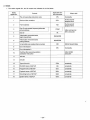
CONTENTS
1. IMPORTANT SAFETY NOTICE
2
2. SAFETY PRECAUTIONS
3
3. FEATURES
4
4. SPECIFICATIONS
5
5. DIMENSIONS
7
6. PREPARATIONS BEFORE USE
8
7. NOMENCLATURE AND FUNCTIONS
9
8. REMOTE CONTROLLER (OPTIONAL)
21
9. DISC
22
10. BASIC OPERATION
11. SETUP OPERATION
24
>.
25
12. PLAYBACK METHODS
33
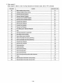
13. RECORDING METHODS [LQ-3031T only]
36
14. DISC ID (RECORD/PLAYBACK METHODS)
39
15. ERASE AND ALTERNATE PICTURE MANAGEMENT
42
16. TIME BASE CORRECTOR CONTROL FUNCTION
45
17. PIN ASSIGNMENTS OF TBC CABLE (OPTIONAL)
47
18. VARIOUS MANUAL OPERATIONS
48
19. RECORDING BY EXTERNAL SWITCH [LQ-3031Tonly]
52
20. ON-LINE OPERATIONS
(1) RS-232C INTERFACE
54
(2) ON-LINE PROCESSING OUTLINE
59
(3) DATA COMMUNICATION PROTOCOL
62
(4) ON-LINE DATA FORMAT
63
(5) ON-LINE FUNCTION
67
(6) FORMAT FOR ON-LINE COMMANDS
72
21. PROGRAMMING
120
22. BASIC CONNECTIONS
132
23. ERROR HANDLING
*
135
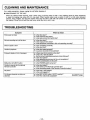
24. CLEANING AND MAINTENANCE
148
25. TROUBLESHOOTING
148
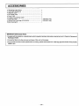
26. ACCESSORIES
149
-1 -
IMPORTANT SAFETY NOTICE
CLASS I LASER PRODUCT
This unit complies with DHHS Rule 21 CFR Chapter 1, Subchapter J in effect as of data of manufacture. This unit contains an
INVISIBLE LASER RADIATION SYSTEM which is classified as a Class I Level Laser Product with its required safety protection.
CAUTION:
Use of controls or adjustments or performance of procedures other than those specified herein may result in
hazardous radiation exposure.
•Do not remove CASE COVER of this unit and never touch anything^ internal in order to avoid EXPOSURE TO LASER
RADIATION.
• If the unit fails to operate properly, please follow the "TROUBLE SHOOTING" section of this manual which lists a few simple
checks in order to determine the cause of failure.
•When the POWER ON/OFF switch is ON, do not put your eyes close to the front panel opening to look inside the unit with the disc
cartridge ejected.
LASER SPECIFICATION:
Class I Level Laser Product
Wave Length:
780 nm or 790 nm [LQ-3031T] / 790 nm [LQ-3032T]
Laser Power:
No hazardous radiation is emitted with safety protection.
WARNING:
To prevent damage which might result in a fire or shock hazard, do not expose this appliance to rain or moisture.
CLASS A DIGITAL DEVICE
This equipment complies with the requirements in Part 15 of the FCC Rules for a Class A digital device.
Note: This equipment has been tested and found to comply with the limits for a Class A digital device, pursuant to Part 15 of the
FCC Rules. These limits are designed to provide reasonable protection against harmful interference when the equipment is
operated in a commercial environment. This equipment generates, uses, and can radiate radio frequency energy and, if not
installed and used in accordance with the instruction manual, may cause harmful interference to radio communications.
Operation of this equipment in a residential area is likely to cause harmful interference in which case the user will be required to
correct the interference at his own expense.
FCC Warning: To assure continued FCC emission limit compliance, use only the provided grounded power supply cord and the
shielded interface cable when connecting this device to the computer.
Also, any unauthorized changes or modifications to this equipment would void the user's authority to operate this device.
'CANADIAN DEPARTMENT OF COMMUNICATIONS (DOC) RADIO FREQUENCY
INTERFERENCE REGULATIONS
Notification: This digital apparatus does not exceed the Class A limits for radio noise emissions from digital apparatus set out in
the Radio Interference Regulations of the Canadian Department of Communications.
Notification: L'interference radioelectrique generee par cet appareil numerique de type A ne depasse pas les limites enoncees
dans le Reglement sur les perturbations radioelectriques, section appareil numerique, du Ministere des Communications.
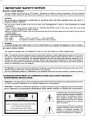
The lightning flash with arrowhead symbol,
within an equilateral triangle, is intended to
alert the user to the presence of uninsulated "dangerous voltage" within the product's enclosure that may be of sufficient
magnitude to constitute a risk of electric
shock to persons.
CAUTION
RISK OF ELECTRIC SHOCK
DO NOT OPEN
CAUTION: TO REDUCE THE RISK OF ELECTRIC SHOCK,
The exclamation point within an equilateral
triangle is intended to alert the user to the
presence of important operating and
maintenance (servicing) instructions in the
literature accompanying the appliance.
DO NOT REMOVE COVER (OR BACK).
NO USER-SERVICEABLE PARTS INSIDE.
REFER SERVICING TO QUALIFIED SERVICE PERSONNEL.
-2-
SAFETY PRECAUTIONS
This unit incorporates many sensitive optical components. To ensure optimum performance at all times, avoid using this unit
under the following conditions.
•
•
•
•
•
•
•
•
•
•
•
•
In a closed vehicle or other location where the temperature could exceed 35°C (95°F).
For long periods of time in direct sunlight.
Very cold places (Below 5°C, 41 °F).
Very humid locations (70% or above).
i
Near a heat outlet or heating appliance.
Dusty or smoky locations.
Locations prone to vibrations or shock.
When placed on an uneven or unstable surface.
Near appliances generating strong magnetic fields.
Immediately above or below a radio, television monitor, tuner or other receiving equipment.
Where there are significant temperature or humidity changes.
Within reach of children.
Do not place near a tuner or TV (television) monitor.
• This unit uses high frequency signals and can cause interference with radio and television reception. If this occurs, move
this unit farther away from the radio or television or change from an interior to an exterior television antenna.
Do not block the ventilation opening.
• This unit is equipped with ventilation openings and a cooling fan to prevent the internal temperature from rising too high.
Therefore, do not operate it with any covering placed over the top or with the unit placed on a bed, deep carpet or other
soft surface. If proper ventilation is obstructed, the internal temperature will rise and the laser diode protection circuit will be
activated to shut off the unit.
Do not place in locations where the rear panel is less than 3 inches away from the wall or back of a rack.
Do not place this unit where ventilation is insufficient.
Do not place any heavy objects on top of this unit.
Never try to remove the cabinet screws or make any adjustments. Serious harm to both the user and unit may result.
Place the unit horizontally on a hard, level and stable surface.
• Vibrations reaching the unit during operation will cause erratic operation and may cause critical adjustments to change.
Severe mechanical shock should be avoided during shipping. Use proper packaging.
When the unit is not in use for a long period of time, always unplug the AC cord from the outlet.
Do not allow the AC power cord to become damaged by crushing or abrasion.
CAUTION:
In case the disc compartment is cracked or bent, please contact the dealer from whom you purchased the unit and replace
the disc compartment in order to avoid EXPOSURE TO LASER RADIATION.
WARNING TO PURCHASERS:
t
The unauthorized recording of copyrighted broadcast programs for commercial purposes is a Copyright infringement.
CAUTION:
This disc contains tellurium which may be considered hazardous. Check applicable Federal, State, and Local regulations in
your jurisdiction prior to disposal. Do not incinerate.
-3-
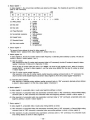
FEATURES
111 Reproduction of clear, high quality image by new signal recording formats.
Horizontal Resolution:
S/N ratio (Signal to Noise):
Normal mode
Hi-Res. mode
More than 45 dB
more than 380 lines
more than 450 lines
12" (300mm) diameter disc greatly increases image capacity.
It is possible to record/playback for; (LQ-3032T is playback only)
Single side: Normal mode
54,000 video frames (30 minutes
Hi-Res. mode
36,000 video frames (20 minutes
Double side: Normal mode
108,000 video frames (60 minutes
Hi-Res. mode
72,000 video fra/nes (40 minutes
motion)
motion)
motion)
motion)
A newly developed tilt servo system is employed, promoting stable recording and playback features (LQ-3032T
is playback only). The unit keeps a certain parallel line between lens and disc, maintaining a high quality image.
4
Composite Video, S-Video, and RGB input/output terminals (LQ-3032T is output terminals only), make connection
of various video signals possible.
Seamless Search (keeping the previous image on the screen during the search mode) and Fine Slow
(slow-motion playback with smooth movement, without picture vibration) can be performed by controlling the
dedicated time base corrector.
6 ] A modular interface card is making, software applications in ROM, dubbing, video guide
etc. possible.
(optional)
\7\ Total computer control is in the On-line mode.
| 8 | Other features.
1) Erase function: [LQ-3031Tonly]
Erase poor or unnecessary frames and record alternate frame search information.
* Picture mute on/off designation is possible activated/deactivated by SETUP.
2) Alternate control function:
Read the address information of recorded alternate frame, and automatically search alternate frame (address information
is in 5 digits figure).
* Functions at search completion time.
t
* Activated/deactivated by SETUP menu.
3) Disc ID record function: [LQ-3031T only]
Possible to rewrite disc volume number record/playback (5 digits) up to 10 times.
4) Automatic start function:
a) Still Playback start by disc loading.
b) Automatic program run.
* Power on Automatic program on/off designation. Activated/deactivated by SETUP.
5) SETUP function:
Drive initialization function.
* On-screen indicator system set up.
* Communications mode, alternate control, automatic start, buzzer, white flag, frame servo
etc.
6) Deck number function:
The unit can be assigned a logical unit number.
0-99 numbers can be assigned to the unit.
* Effective for multi unit structure system.
7) User's area SETUP function:
Functions to divide 54,000 frames of user's area into small sections.
* Effective for dividing information on disc, classifying according to items, users, and effective for the Remote Controller
and On-line combined applications.
-4-
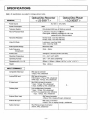
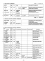
SPECIFICATIONS
Note: All specifications are subject to change without notice.
GENERAL
Optical Disc Recorder
<LQ-3031T>
AC 120V ± 10%,60Hz
Power Source
Power Consumption
Optical Disc Player
< LQ-3032T >
125W
100W
Television System
EIA standard (525 lines, 60 fields per second)
Record/Playback Mode
Luminance; frequency modulation
Color signal; frequency modulation R-Y/B-Y line
sequential color difference signal
Horizontal Resolution
Normal mode; more than 380 lines
Hi-Res. mode; more than 450 lines
Video S/N Ratio
Luminance; more than 45dB
Color; more than 45dB
Audio Dynamic Range
More than 70dB
Audio Frequency
Characteristic
20Hz ~ 20kHz
Access Time
Average 0.7 seconds (at Gen Lock OFF)
Operating Temperature
5 ° C ~ 3 5 ° C (41°F-95°F)
Operating Humidity
30% ~ 70% (Non condensing)
Dimensions (W x H x D)
430mm x 155mm x 546mm (16 15 /ie" x 61/8" x 21V2" )
Weight
18kg
(40 lbs.)
INPUT TERMINALS
Composite Video Input
BNC type of connector
1.0Vp-p, 75ft, unbalanced
Analog RGB Input
BNC type of connectors
R.G.B inputs; 0.7Vp-p, 75ft, unbalanced
SYNC input; 4.0Vp-p, 75ft, unbalanced
S-Video Input
Mini DIN 4 pin type of connector
Y input; 1.0Vp-p, 75ft, unbalanced
C input; 0.286Vp-p, 75ft, unbalanced
Dubbing Input
V
5 pin multiple type of connector
Y input; 1.0Vp-p, 75ft, unbalanced
R-Y/B-Y line sequential color difference
input; 1.0Vp-p, 75ft, unbalanced
External Sync. Input
BNC type of connector
4.0Vp-p, 75ft or looping through, unbalanced
External SC Input
BNC type of connector
2.0Vp-p, 75ft or looping through, unbalanced
Audio Line Input
RCA Phono pin type of connector
316mV, 47kft, unbalanced
-5-
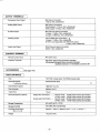
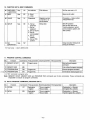
OUTPUT TERMINALS
Composite Video Output
BNC type of connector
1 .OVp-p, 75ft, unbalanced
Analog RGB Output
BNC type of connectors
R,G,B outputs; 0.7Vp-p, 75ft, unbalanced
SYNC output; 4.0Vp-p, 75ft, unbalanced
S-Video Output
Mini DIN 4 pin type of connector
Y output; 1 .OVp-p, 75ft, unbalanced
C output; 0.286Vp-p, 75ft, unbalanced
Dubbing Output
5 pin multiple type of connector *
Y output; 1 .OVp-p, 75ft, unbalanced
R-Y/B-Y Line sequential color difference output;
1 .OVp-p, 75ft, unbalanced
Audio Line Output
RCA Phono pin type of connector
400mV, 1 kft, unbalanced
CONTROL TERMINAL
Remote Control Input
Mini Jack (1 pc.)
Interface Terminals
RS-232C; 25pin D-Sub connector (Female)
I/O terminal; half pitch 20 pin connector (Female)
matched connector; 10120-6000EL Sumitomo 3M
ACCESSORIES
(Seepage 149.;
DISC/CARTRIDGE
Disc
TQ-FH331 (single side), TQ-FH332 (double side)
Record/Playback
Luminance Source
Semiconductor laser
<
1
Disc Rotation Speed
1800 min" (r.p.m.)
Disc Diameter
300mm (o12")
Track Pitch
1.6jnm
Record/Playback Capacity
Single side (TQ-FH331)
Double side (TQ-FH332)
Normal mode; 54,000 video frames (30 minuites)
Hi-Res. mode; 36,000 video frames (20 minuites)
Normal mode; 108,000 video frames (60 minuites)
Hi-Res. mode; 72,000 video frames (40 minuites)
Storage Temperature
50C~450C(410F-113°F)
Storage Humidity
10%~80% (Non condensing)
Cartridge Dimensions
(W x H x D)
340mm x 18mm x 350mm (133/s" x
Weight
1 kg (27/32 lbs.)
-6-
11
/i6" x 1325/32")
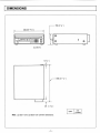
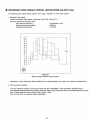
DIMENSIONS
•155(6 Vs")
430((|16
15
/16")
# •
I D
I
n
o
l_l
QS5SS|
||
|
a
n
• • •
a n a
)d a o a
\
DD
DO
DD
•
•
l_l
OLQ-3031TU
6(V4")
-546 (21
1
/2")
29 (1 V s " )
UNIT
Note: LQ-3031T and LQ-3032T are common dimensions.
7-
mm
dinches)
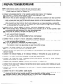
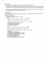
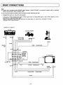
PREPARATIONS BEFORE USE
STEP 1: Decide where to place this unit observing the safety precautions on page 3.
STEP 2: Connect the unit to the external equipment, following the procedures below.
Consider that you are working with an analog unit!
A. CONNECT A TELEVISION MONITOR TO THE VIDEO OUT AND/OR VIDEO DISPLAY OUT TERMINALS.
• Verify that the TV monitor to be used will accept a standard NTSC video signal (1Vp-p).
• Read the operating instructions for the monitor completely.
• Connect the Video Out and/or Video Display Out terminals of this unit (BNC type of connector) to the video input terminal
of the TV monitor. Be sure to use a high quality cable, such as RG-59U. (No audio cable with adapters or zip cord)
• When connected to the Video Display Out terminal, the address information and the any other data of the units movement
is indicated on the monitor display.
• When connected to the Video Out terminal, the TV monitor indicates no data, just images, unless display is activated "ON".
Note: The above procedures may be followed for any equipment that will be connected to the Vide* Out and/or Video Display
Out terminals. These are composite video outputs.
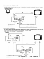
B. CONNECT THE EXT. SYNC IN TERMINAL TO THE EXT. SYNC SIGNAL GENERATOR [If desired].
• An external sync signal (4Vp-p, 75H, BNC type of connector) may be connected to the unit. This input is provided to assist
in synchronizing many pieces of equipment, such as in a broadcast application.
• Verify the level and impedance of the signal to be supplied to the unit.
• Connect the desired signal to the appropriate terminal. For Gen Lock applications, a sync delay adjustment display must
be used. A waveform monitor is best suited.
Note: The Ext. Sync In terminal is looping through with the Ext. Sync Out terminal.
If no connection is made to the output terminal, this input is 75fi terminated.
C. CONNECT THE EXT. SC INPUT TO THE EXT. SYNC SIGNAL GENERATOR [If desired.]
• An external subcarrier signal (2Vp-p, 7511, BNC type of connector) may be connected to the unit in order to synchronize
the video signal subcarrier with other device.
• For Gen Lock applications, a vectorscope is used to adjust SC phase.
Note: The Ext. SC In terminal is looping through with the Ext. SC Out terminal.
If no connection is made to the output terminal, this input terminal is 75fl terminated.
D. CONNECT THE RS-232C CONNECTOR TO A COMPUTER [If desired].
• Be sure you have the proper configuration of the RS-232C cable.
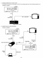
E. CONNECT THE EXT. SYNC AND/OR EXT. SC OUT TERMINALS TO THE RESPECTIVE INPUT TERMINALS OF THE OTHER
DEVICE [If desired].
F. CONNECT THE VIDEO IN TERMINAL TO THE VIDEO OUT TERMINAL OF THE SOURCE [If desired]. [LQ-3031Tonly]
G. CONNECT THE REMOTE CONTROLLER [If desired]. (It is not an infared remote controller)
H. CONNECT THE R.G.B. SYNC IN/OUT TERMINALS TO THE OTHER DEVICE THAT HAS THE R.G.B. TERMINALS
[If desired]. [Input terminals are LQ-3031T only]
I. CONNECT THE AUDIO IN/OUT TERMINALS [If desired]. [Input terminals are LQ-3031T only]
J. CONNECT THE S-VIDEO IN/OUT TERMINALS TO THE OTHER DEVICE WHICH HAS THE S-VIDEO TERMINALS [If desired].
[Input terminal is LQ-3031T only]
K. CONNECT THE DUB IN/OUT TERMINALS TO THE OTHER UNIT TO OPERATE DUBBING [If desired]. [Input terminal is
LQ-3031T only]
L. CONNECT THE UNIT TO THE CORRECT POWER SOURCE.
• The unit is designed for 120 V ±10%, 60 Hz AC power. The use of any other power source may damage the unit.
If you are not sure that the power source to be used is correct, contact your local power company.
• Verify that the output to be used is 3 prong grounded type. The unit must have a good grounding at all times.
• Connect the power cord to the unit first, and then to the AC outlet.
-8-
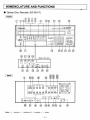
NOMENCLATURE AND FUNCTIONS
Optical Disc Recorder [LQ-3031T]
FRONT
m
(g)(9) j @ j!
JJ <3>[H
Pan asoi lie
in
Optic al Disc Re< ;order
m
ATT\
ia
tE
0
-KT^
LJ
»-|—
•
DIO P.EC I
m E
f I
m m
rnirri EEJ
DISI LAV
I -Ti I 11 lit |
S T S ]
20 21 22
18
27 28 29
25 24
<Behind the door>
GEN OCK REC .EVEL
<g #e {j& gp
SC PHASE
B T S
STILL STEP
®
SET UP
LQ-3031T
LZILZILZ]
CMODt I
26
15
#
T . AUDIO .7 -
fl"
H P LASE
A
-
T.
J-—CII2M
S-ViMo 1—TRGE
31
32
30
33
M
M
34
35
MM
REAR
AL J10
CHI I CHS
( ,
I
Slf4C
(©(g)
FUSE
1.6A AC 125V
r © ) © ®©-i<§h
O / t
V> 6
©
1 1 1
Note: •
controls, o
indicators, Q
MM
terminals, o
others
- 9 -
<$>
H
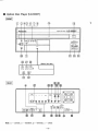
Optical Disc Player [LQ-3032T]
FRONT
o
E] ©(3X5) © (7) (D
Panasonic
Optical Disc Player
L Q - 3 0 3 2 T
PO rfER
m
CiBrEL]
®
I «ti I Ll g I
PUSH
®
^ T S
m E
22
26
27
28
SET UP
DISI LAV
GEN OCK
<Behind the deor>
SCF <ASS
H P IASE
31
32
REAR
R
G
B
SYNC
FUSE
«A AC 125V
s-vioeo Dua
Q/.... t .....ta
GROUND
6
III! 4>
Note: •
controls, o
indicators, •
terminals, o
others
-10-
25
24
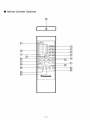
Remote Controller (Optional)
C
21
19
17
m
27
3$
20
© © ©
© © ©
© © ©
©^
PAUSE
H-S
H-B
H-B
H-B
-23
STILL
-24
-25
REC fflODE START-STOP AUDIO REC
i
DISPLAY
SETUP
LZZ:
CHI - AUDIO -
QCH2
: c
16
•EZJERASE
WRITE
-18
"37
ALTERNATE
1
'
READ
PROGRAM
ENTER
RUN
39
in
1
4P
41
-22
Panasonic
-11 -
•26
s
-42
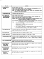
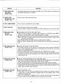
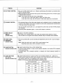
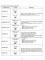
PURPOSE
ITEM NO.
[Q POWER ON/OFF
SWITCH
• POWER ON/OFF SELECTION.
• Press this button, Power indicator (@) lights, indicating that the power of the unit is ON.
• Press this button again, the power of the unit is turned OFF.
Note: When this button is pressed turning the power ON, and when disc is already loaded
into the unit, disc startup is automatic.
(2) POWER INDICATOR
• This indicator lights with power ON.
[3] ON-LINE BUTTON
(ON-LINE/OFF-LINE
SELECT BUTTON)
• ON-LINE/OFF-LINE SELECTION.
• Press this button, On-line indicator ( © ) lights, indicating the unit is in the On-line mode.
• Press this button again, the unit returns to manual operation.
[ON-LINE mode]: Control of all functions are transferred to an external computer. (This is
controlled by signals sent through RS-232C terminal.)
[OFF-LINE mode]: Computer control is disabled and control of all functions are transferred to
the front panel of the unit and Remote Controller.
Note: 1) When in On-line mode, both the front panel and Remote Controller do not function,
except for the ones below:
• POWER ON/OFF • ON-LINE ON/OFF • GEN LOCK
• REC LEVEL [LQ-3031T only]
2) When this button is depressed, the operation status in the mode before On-line is
set will continue until an instruction is given from the On-line side.
(§) ON-LINE INDICATOR
• This indicator lights when ON-LINE burton (|"3"|) is pressed, or unit is brought On-line by computer, and indicates the unit is in On-line mode.
(5) DISC INDICATOR
• This indicator lights when a disc cartridge is loaded in the unit.
(6) HI-RES INDICATOR
• This indicator lights when a disc cartridge (in Hl-Res. mode) is loaded.
(7) PROGRAM INDICATOR
• This indicator lights if PROGRAM RUN button (|43|) of remote controller is pressed. This
indicates the unit is in Program Run mode. It can also be activated through the RS-232C
interface.
(8) GEN LOCK INDICATOR
• This indicator lights only when Gen Lock function is operating.
Note: Gen Lock indicator indicates that video In/Out phase is locked.
(9) INPUT INDICATOR
(VIDEO INPUT)
[LQ-3031Tonly]
• This indicator lights when Input Select switch ([33]) is set to "VIDEO" position, and indicates
that the composite video input signal is selected.
®
INPUT INDICATOR
(S-VIDEO INPUT)
[LQ-3031Tonly]
• This indicator lights when Input Select switch (|33l) is set to "S-VIDEO" position, and indicates
that the S-Video input signal is in operation.
(Q) INPUT INDICATOR
(RGB INPUT)
[LQ-3031Tonly]
• This indicator lights when Input Select switch ([33]) is set to "RGB" position, and indicates that
the RGB input signal is in operation.
-12-
PURPOSE
ITEM NO.
@ INPUT INDICATOR
(DUB INPUT)
[LQ-3031Tonly]
• This indicator lights when Input Select switch (|33|) is set to "DUB" position, and indicates that
the dubbing input signal is in operation.
(Q) AUDIO LEVEL
METERS (CH1. CH2)
[LQ-3031Tonly]
• Used to monitor audio input/output levels.
<$> DISC COMPARTMENT
• This is the slot to insert/eject the disc cartridge.
H I EJECT BUTTON
• Press this button to eject the disc cartridge.
^
When this button is pressed, Disc indicator and Hi-Res. indicator go out, and the unit stops.
[ H REC START-STOP
BUTTON
[LQ-3031Tonly]
• RECORDING START/STOP (REC MODE ONLY).
• When this button is pressed in recording ready conditions in the RECORD mode the^LED
indicator on this button lights, and the recording operation is started.
• Before pressing this button, input the number of frames to record with the number buttons ([T9J).
Note: If this button is pressed without inputing the frame number desired to record to only
one frame will be recorded.
• After finishing recording, this again returns to recording ready conditions.
• When this button is pressed again, the LED indicator goes off, and stops the recording operation.
07] REC MODE BUTTON
[LQ-3031Tonly]
• ON/OFF SELECTION OF THE REC MODE.
• If this button is pressed, the LED indicator on this button lights, and the unit goes into RECORD
mode. It then automatically searches for a non-recorded area of the disc, the unit is then
ready for the recording operation.
• If button is pressed again, the LED indicator goes out a RECORD mode is exited.
• If the number of frames to record is input with the number buttons prior to pressing this button,
it searches only the area that corresponds to the number of frames wanted to record. This
reduces search time.
( H AUDIO REC BUTTON
[LQ-3031Tonly]
• SELECT AUDIO RECORDING OR NOT (REC MODE ONLY).
• If this button is pressed immediately after pressing REC MODE button (|TJ), the LED indicator
lights, and audio recording (synchronized to video signal) is enabled.
• If button is pressed again, the LED indicator goes out and audio recording is disabled.
• Once recording starts by pressing REC START-STOP button (jj6|), audio recording cannot be
enabled even if this button is pressed during recording. If audio recording is desired, do not
forget to press this button before recording.
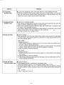
QJ NUMBER BUTTONS
[LQ-3031Tonly]
• INPUT NUMERICAL DATA.
• These buttons "0—9" are used when specifying the frame address to be searched, recorded,
or played back, and when specifying the playback speed in each playback mode, or when
entering any numerical data.
• When "E01 OVERFLOW" is displayed on the TV monitor, data from these number buttons
is wrong. Press the CE button (^0]) to clear the incorrect entry and reenter.
-13-
PURPOSE
ITEM NO.
CE BUTTON
[LQ-3031Tonly]
• CLEAR THE NUMERICAL DATA THAT WAS INPUT BY THE NUMBER BUTTONS.
• This button functions to clear incorrect entries input with the number buttons. If an incorrect
entry was made with the number buttons, press this button to clear the previous entry. The
correct entry can be reinput with the number buttons again.
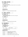
|T] SEARCH BUTTON
[LQ-3031Tonly]
• SEARCH TO ADDRESS FRAME.
• After selecting the target address using the number buttons at the playback mode, press this
button to make the selected frame appear on monitor screen.
• When search operation exceeds the specified range, "E01 OVERFLOW" is displayed on the
TV monitor, and no operation will occur.
• If this button is pressed without designating the target address to be searched via the number
buttons, the first frame of the user's define area will be searched.
-^
• This button functions only in playback mode.
H
SCAN BUTTONS
I SKIP PLAYBACK.
1
When playing back in the Play, Step, Fast and Slow modes, press this button for a high speed
On-screen search. (Skip playback operation is performed at a speed approximately 50 times
the normal playback speed.)
[FWD. SCAN]
<Playback Operation>
1) When playback operation is performed up to the final user's define area address frame,
the STILL mode is selected automatically.
2) If button is pressed, about 280 frames will be jumped in a forward direction, then playback
therefor 4 frames (about from 281 to 284) will be displayed in sequence.
3) Hold the button for continuous scanning.
[REV. SCAN]
<Playback Operation>
1) If button is pressed, about 280 frames will be jumped in a reverse direction, then playback
for 4 frames.
2) Hold the button for continuous scanning.
3) When Reverse Scanning is performed to the first frame of the user's define area, the STILL
mode is selected automatically.
SLOW BUTTONS
[remote controller only]
• SLOW PLAYBACK
• SLOW playback operation is performed in the playback mode.
(The SLOW playback speed is 1/3 of the standard playback speed 10 FPS.)
• Any SLOW playback speed, from 1/2 to 1/256 normal speed, may be selected by entering
the desired speed (2-256) by pressing the value on the number buttons before touching this
button.
1/2;
15 FPS.
1/256; 1 frame every 8.5 sec.
-14-
ITEM NO.
PURPOSE
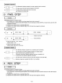
[FWD. SLOW]
1) If button is pressed when unit is not playing, it starts SLOW playback in a forward direction.
2) If button is pressed when operation mode is in "ERASE" it first clears the ERASE mode
then starts SLOW playback in the forward direction.
3) If button is pressed when operation mode is in "RECORD" it first clears the RECORD
mode then starts SLOW playback in the forward direction from the first frame recorded at
this time.
[REV. SLOW]
1) If pressed when unit is not playing it performs STILL playback.
2) If pressed when operation mode is in "ERASE" it first clears the ERASE mode then starts
SLOW playback in the reverse direction.
3) If button is pressed when operation mode is in "RECORD" it first clears the RECORD
mode then starts SLOW playback from the last frame recorded at this time in the reverse
direction.
*
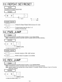
M STILL/STEP BUTTONS
• STILL OR STEP PLAYBACK.
• Press this button to stop the disc playing clear the playback mode operation, and have the
unit display a single frame continuously.
• To move one frame or for automatic frame advance, enter a figure between 1 and 256 via
the number buttons before pressing this button.
• To return to playback mode, press the appropriate button for that mode.
• Holding this button depressed for more than 2 seconds causes frames to be advanced at a
rate of four per second.
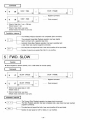
[FWD. STEP]
<Playback Operation>
1) If button is pressed when unit is in STILL playback or STEP playback, it advances 1 frame
in the forward direction.
2) If burton is pressed after inputing figures from 1 to 256 with the number buttons, it begins
STEP playback at 1 - 2 5 6 second intervals.
3) If button is pressed when unit is not booted, it performs STILL playback from the first frame
of the user's define area.
4) If button is pressed when operation mode is in "ERASE" it clears the ERASE mode first
then performs STILL playback, then starts STEP playback in the forward direction.
5) If button is pressed when operation mode is in "RECORD" it clears RECORD mode then
starts STILL playback of the first frame recorded at this time, then starts STEP playback
in the forward direction.
[REV. STEP]
<Playback Operation>
If pressed when unit is not activated, it performs STILL playback from the first frame of the
user's define area.
1 1 PLAY BUTTONS
• NORMAL OR FAST PLAYBACK.
• Press this button to begin normal disc playback.
(One times normal speed = 30 frames/second)
• If pressed after inputing a figure of 1—10 with the number buttons, it starts FAST playback
at 1—10 times normal speed. (I.e. 3 would cause 90 FPS play)
15-
ITEM NO.
PURPOSE
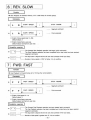
[FWD.PLAY]
<Playback Operation>
When playback operation is performed up to the final frame, the STILL playback is selected
automatically.
[REV. PLAY]
^
<Playback Operation>
When playback operation is performed down to the first frame of the user's define area, the
STILL playback is selected automatically.
m SETUP BUTTON
• ON/OFF SELECTION OF SETUP MODE.
• If pressed it selects SETUP mode.
• If pressed again SETUP mode is cleared.
Note: concerning SETUP function, refer to page 25.
DISPLAY BUTTON
• ON/OFF SELECTION OF ON-SCREEN DISPLAY.
• If pressed, various On-screen data is displayed on the TV monitor, which is connected to
each output terminal of Video/S-Video/RGB, if pressed again the On-screen indication is turned
OFF.
Note: Data indicated On-screen.
• Frame No. • Input Data • Operation Mode • Error Message
28 GEN LOCK BUTTON
• ON/OFF SELECTION OF GEN LOCK OPERATION.
• If pressed, Gen Lock function is activated, and Video Output Signal is automatically synchronized to Ext. Sync. Phase adjustment is done with the H-PHASE control (§!) and SC
PHASE control (gj).
• Gen Lock indicator lights only when Gen Lock function of unit is operating correctly.
Note: Do not attempt Gen Lock when using external TBC.
See SETUP Operation at page 25, for TBC ON/OFF.
[ 2 | REC LEVEL BUTTON
[LQ-3031Tonly]
• SELECT THE REC LEVEL ADJUSTMENT AUTO OR MANUAL.
M
• This control adjusts the recording level of the video input signal when REC LEVEL button is
in the MANUAL mode.
Turn the control knob and set the knob to the position where the green lamp lights.
Note: The Rec level indicator may take a few seconds to stabilize.
The indicator measures sync level.
REC LEVEL CONTROL
[LQ-3031Tonly]
• This button selects the manual or automatic level adjustment of the video recording signal.
<MANUAL>
The video recording level can be adjusted by Rec Level control (|30|).
RED
Video recording level is too high.
GREEN
Video recording level is suitable.
ORANGE
Video recording level is too low.
<AUTO>
The video input level is adjusted automatically.
16
ITEM NO.
PURPOSE
U SC PHASE CONTROL
• Be sure the GEN LOCK button is on. Observe vectorscope while locked to an external reference for accurate setting.
• Match SC phase of unit to the other video source at final mixing point (P.V.W. or P.B.M. output)
of Special Effect Generator.
Note: This function will not work for the cases below.
• Gen lock to Ext. Video input signal in Black and White video.
• Gen lock to Ext. Sync, Ext. SC and Ext. Video input signal are not connected.
QZ H-PHASE CONTROL
• The horizontal phase of the video output signals can be adjusted to that of a (another) signal
at the Ext. Sync signal of this unit by turning this control while comparing the horizontal sync
of the input versus the output video.
Be sure the GEN LOCK button is on, and adjust this control knob until the H-SYNC phases
are coincident.
• Horizontal phase adjustable approx. ± 3/j.sec with respect to reference.
H
INPUT SELECT
SWITCH
[LQ-3031Tonly]
• SELECT THE INPUT SIGNALS.
• This switch is for choosing which of the video input signal formats desired to record.
Set the switch to the signal format desired (indicator lamp will indicate format selected).
|34] AUDIO LEVEL
H CONTROLS
[LQ-3031Tonly]
• This unit is provided with a sound recording level adjustment control for CH 1 and CH 2 respectively.
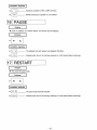
| | PAUSE BUTTON
[remote controller only]
• ON/OFF SELECTION FOR A STOP OPERATION.
• If pressed during playback, it stops current playback operation, and invokes STILL playback
at the current frame.
• If pressed again, STILL playback operation is released and forward playback operation is
resumed.
H I AUDIO BUTTONS
(CH 1/CH 2)
[remote controller only]
• ON/OFF SELECTION OF AUDIO OUTPUT IN PLAYBACK MODE (CH 1 AND CH 2).
• These buttons change the audio output conditions of the audio channels. When these buttons
are pressed, button set up is displayed on the monitor screen.
• Based on the set up, audio output changes as following chart.
Note: Adjust the audio level to read 100% at peak program input.
Recording levels above 100% will distort the sound.
BUTTON SETTING
AUDIO OUTPUT
AUDIO CH1
AUDIO CH 2
CH1
CH2
ON
ON
CH1
CH2
ON
OFF
CH1
CH 1
OFF
ON
CH2
CH2
OFF
OFF
MUTE
MUTE
17-
PURPOSE
ITEM NO.
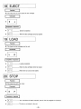
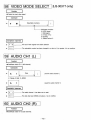
H
ALTERNATE BUTTON
[remote controller only]
I ON/OFF SELECTION OF ERASE MODE.
If button is pressed when in playback mode unit shifts to ERASE mode and displays STILL
playback on the frame currently in playback. If pressed again, ERASE mode is cleared.
In ERASE mode, writing and reading of alternate picture address data is possible.
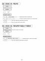
H
ERASE BUTTON
[remote controller only]
• ERASE DISC ID No.
• When in playback mode, if ERASE button is pressed after Disc ID No. is input with the number
buttons, it erases the written Disc ID No. only when the input Disc ID No. and written Disc
ID No. are the same.
After erasing, unit searches in the first frame of the user's define area.
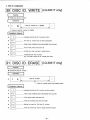
M WRITE BUTTON
[remote controller only]
• INPUT DISC ID No.
• When in playback mode, if pressed after Disc ID No. is input with the number buttons, the
Disc ID No. is written to the disc.
• Select Disc ID No. from 0 99999 range.
• After finishing Disc ID No. writing, it performs STILL playback in the first frame of the user's
define area.
• When in ERASE mode, if pressed after input of alternate picture address data, it is written
on frame in STILL playback.
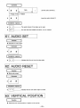
gT| READ BUTTON
[remote controller only]
• READ DISC ID No.
• If pressed when in the playback mode, unit reads the Disc ID No. and an On-screen indication
is displayed on the TV monitor, after read is finished, unit performs a STILL playback on the
first frame of the user's define area.
• If pressed when in ERASE mode, unit reads the alternate picture frame address which is
written in the STILL playback frame, and displays an On-screen message on the TV monitor.
( H ENTER BUTTON
[remote controller only]
• INPUT FIGURES WHILE IN A PROGRAM OPERATION.
• When a figure is input while the program is in execution, press this button after desired figure
has been input with the number buttons.
143] PROGRAM RUN
BUTTON
[remote controller only]
I SELECT START/STOP OF THE PROGRAM OPERATION.
If button is pressed after inputting new medical data of 0—4 (default values are designated
via SETUP) with the number buttons.
Program Run Indicator lights and the designated program is retrieved from programs stored
in the units' program memory, the unit starts operation according to the command of the chosen
program.
Note: If this button is pressed again, the program currently executing is stopped, RECORD
mode and ERASE mode are cleared, then STILL playback is performed at the current
playback address.
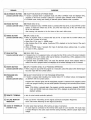
H
REMOTE TERMINAL
Jack for wired remote controller (optional).
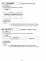
ON-LINE MONITOR
INDICATOR
Red LED shows Transmitting On-line Signal (Command Completion Response).
Green LED shows Receiving On-line Signal (Command).
AUDIO IN TERMINALS
[LQ-3031Tonly]
• Audio signal input terminals. (RCA phono pin type of connector)
An audio signal is connected to this terminal when audio is to be recorded. The audio input
is looped through to the audio output terminal during recording. Observe proper signal input
voltage.
18-
ITEM NO.
M AUDIO OUT
TERMINALS
PURPOSE
Audio signal output terminals. (RCA phono pin type of connector)
In playback mode, the audio from a recorded disc is output.
RGB & SYNC IN
TERMINALS
[LQ-3031Tonly]
• Terminal to connect to color video source (camera
etc.) which has RGB & Sync output
terminals, and to record video signal sent from there. (BNC type of connector)
RGB & SYNC OUT
TERMINALS
• Terminal to connect equipment which has RGB & Sync input terminals, such as a color monitor,
video printer
etc. (BNC type of connector)
M VIDEO DISPLAY OUT
TERMINAL
• Terminal to connect to video input terminal of NTSC monitor when disc data on the monitor
screen is desired (example of data; address information, operational condition, etc). (BNC
type of connector)
M
23 VIDEO IN TERMINAL
[LQ-3031Tonly]
Video signal input terminal. (BNC type of connector)
Composite signals to be recorded are input (attached) here. (NTSC STD.1.0Vp-p max. when
terminated by 75fi)
VIDEO OUT TERMINAL
• The output through this terminal is a 1 Vp-p, 75il NTSC composite video signal. (BNC type
of connector)
EXT. SC IN TERMINAL
• This terminal accepts a 2 Vp-p, 3.58MHz subcarrier input in order to synchronize the video
signal subcarrier with other devices when the unit is used in a system. (BNC type of connector)
EXT. SC OUT
TERMINAL
H EXT. SYNC IN
TERMINAL
! i | EXT. SYNC OUT
TERMINAL
• This terminal is a loop through for the Ext. SC input terminal. (BNC type of connector)
If no connection is made to this output terminal, the input terminal is 75ft terminated. (See
"GEN LOCK" item)
This terminal accepts a 4 Vp-p RS-170A composite synchronizing signal (See "GEN LOCK"
item). (BNC type of connector)
• This terminal is a loop through for the Ext. Sync input terminal. (BNC type of connector)
If no connection is made to this output terminal, the input terminal is 75ft terminated.
RS-232C CONNECTOR
• Standard serial interface (RS-232C) is provided to facilitate control using computers with a
serial interface (Serial interface port card on computer required).
S-VIDEO IN TERMINAL
[LQ-3031Tonly]
• Connect to color video camera etc, that has on S-Video output terminal to record separated
Y/C signal. (Mini DIN 4 pin type of connector)
Y: luminance, C: chromanance.
M DUB IN TERMINAL
[LQ-3031Tonly]
• Connect from another unit that has a dubbing output terminal to make a copy (dub) of a
recorded disc. (5 pin multiple type of connector)
M S-VIDEO OUT
TERMINAL
• Connect to a color monitor etc, that has on S-Video input terminal, to playback separated
Y/C component type signal. (Mini DIN 4 pin type of connector)
-19-
PURPOSE
ITEM NO.
Connect to another unit, that has dubbing input terminal to make a copy (dub) of a recorded
disc. (5 pin multiple type of connector)
M DUB OUT TERMINAL
M GROUND TERMINAL
1
This terminal is for grounding. It is used mainly when the unit is placed on metallic table. It
is preferable however, to have the unit solidly grounded at all times.
• Unscrew screwcap to remove fuse 1.6A. For use by serviceman only.
FUSE HOLDER
M POWER SOCKET
65 JACK FOR CABLE
Attach the power cord to this socket before inserting the power plug into the wall socket.
• For the wired Remote Controller use.
Recording or playback control by an external switch. (See pages 52-53.]
Controlling the dedicated time base corrector. (See pages 45-46.)
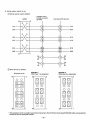
(66 I/O TERMINAL
Note: EXT. SC and EXT. SYNC TERMINALS.
These terminals have an automatic termination switch.
If no connection to the Throughout Terminal, input impedance is 7511 terminated. If the Throughout Terminal is connected, the 7511 terminator is automatically released.
IN
IN
-0-
OUT
+
OUT
75H
*• Connect to Throughtout
Terminal.
-20-
P *750
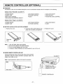
REMOTE CONTROLLER (OPTIONAL)
FUNCTION
All functions of the unit are enabled through the use of the Remote Controller with the exception of the following:
Optical Disc Recorder [LQ-3031T]
•
•
•
•
POWER ON/OFF
ON/OFF-LINE
REC LEVEL CONTROL
REC LEVEL AUTO/MANUAL SELECT
• GEN LOCK ON/OFF
• INPUT SELECT
• AUDIO REC LEVEL CONTROL
• SC PHASE CONTROL
• H-PHASE CONTROL
• EJECT
Optical Disc Player [LQ-3032T]
• POWER ON/OFF
• ON/OFF-LINE
SC PHASE CONTROL
H-PHASE CONTROL
• GEN LOCK ON/OFF
• EJECT
BATTERY INSTALLATION AND REPLACEMENT
1. Remove the cover.
Note: 1.
2.
3.
4.
2. Insert two UM-4 (AAA) batteries (supplied) into the battery compartment.
3. Replace the cover,
Use only UM-4 (AAA) type batteries.
Be sure the batteries are inserted properly.
Do not use old batteries with new ones.
Panasonic Alkaline Batteries are recommended for use in this unit.
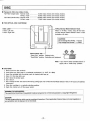
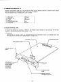
WIRED REMOTE CONTROLLER USE
Connect remote jack of the unit to the top of the remote controller
transmitter using the remote controller's accessory cable. The
length of the cable is 2.5m.
[LQ-3031T]
Note: Avoid bending the cable at its terminal connection.
i—-
REMOTE IN Jack
CONNECTING CABLE
•REMOTE OUT Jack
REMOTE CONTROLLER
21
DISC
Panasonic offers two kinds of disc.
TQ-FH331 (single side): Normal mode
Hi-Res. mode
TQ-FH332 (double side): Normal mode
Hi-Res. mode
54,000
36,000
108,000
72,000
video
video
video
video
frames
frames
frames
frames
(30
(20
(60
(40
minutes
minutes
minutes
minutes
motion)
motion)
motion)
motion)
THE OPTICAL DISC CARTRIDGE
7^
ST
Index Label
A side: Left side
B side: Right side
- Hi-Res./Normal Mode Selector Hook
When in "Hi-Res." mode, snap off the hook.
(Hi-Res./Normal Mode Selector Hook is also
available at B side.)
&
\
CAUTION:
Do not change from Hi-Res. -»Normal
Only change from Normal — • Hi-Res.
D
L
°J
Write Protect Tab—
"Read Only" position: Playback only.
"Read/Write" position: Recording and playback.
Note: If you want to keep recorded picture or
signal, set to "Read Only" position.
CAUTIONS
1. Never touch the disc surfaces.
2. Avoid direct sun light, keep in a moderate environment. (5-45°C, 10-80%)
3. Insert the cartridge with the shutter mark for desired side face up.
4. Store it in the case after use.
5. Don't force the shutter open.
6. Don't drop it.
7. Don't change Hi-Res. disc back to Normal by putting tape over Hi-Res./Normal Mode Selector Hook, it will cause unit address
malfunction.
8. Store disc cartridge in a vertically standing position.
9. Eject disc, before turn off the power switch.
WARNING TO PURCHASERS:
The unauthorized recording of copyrighted broadcast programs for commercial purposes is a Copyright infringement.
CAUTION:
This disc contains tellurium which may be considered hazardous. Check applicable Federal, State, and Local regulations in
your jurisdiction prior to disposal. Do not incinerate.
-22-
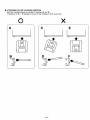
ATTENTIONS FOR DISC CARTRIDGE INSERTION
Insert disc cartridge properly as indicated in drawings ® and ® .
If inserted as in © ~ © damage to the unit or disc cartridge, or both, could occur.
X
J
V
-23
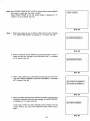
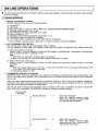
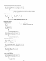
BASIC OPERATION
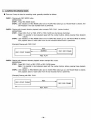
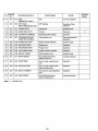
1. INITIAL OPERATION
Press the POWER burton on the front panel of the unit, Power indicator will light,
the power is ON.
On-screen display [Fig. 1] is indicated on the TV monitor.
Note: If the unit detects abnormalities in the unit, the On-screen indication
changes from a • mark to s mark, and blinks on and off. In such cases,
turn the power off, and call an authorized Panasonic service technician.
OPTICAL DISC
RECORDER
(or "PLAYER")
SELF CHECK •
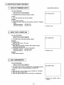
Insert a disc cartridge into the disc compartment, the disc indicator on the front
panel will light.
D
•
Fig. 1]
When the disc cartridge is set to designated position, the On-screen indication
changes to STANDBY [Fig. 3], While the disc gains the proper RPM for operation.
Note: As start up advances, " • " mark of On-screen indication disappears from
right to left.
Disc indicator lights and the first address of disc displays, (when loaded disc is
in Hi-Res. mode, HI-RES indicator also lights)
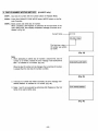
Note:
1) If FWD. PLAY, FWD. STEP, or FWD. SLOW is pressed before Still Playback
starts, unit starts playback operation according to the button from the first frame
of disc.
OPTICAL DISC
RECORDER
(or "PLAYER")
SELF CHECK •
[Fig. 2]
2) In cases of start up by program, starting frame and operation are done according to the program.
3) When POWER button is pressed, if disc is already loaded into unit, disc start
up automatically begins.
In this case, only [Fig. 1] is indicated On-screen.
Q«fc£-
STANDBY
D D D
4) When POWER burton is pressed turning on power, when program Auto Start
is set up, unit will start operation according to the program.
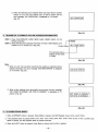
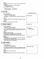
2. DISC EJECTION
[Fig. 3]
1. Press the EJECT button.
2. Disc indicator and HI-RES indicator disappear (when in Hi-Res mode), and Onscreen message indicate "EJECT" and blinks on and off. [Fig. 4]
i i l i i
: EJECT:
TTTT f
3. The On-screen indication changes to "PLEASE LOAD THE DISC" and blinks on
and off. [Fig. 5]
[Fig. 4]
'PLEASE LOAD THE DISC I
T T T T T T T f T Y T T
24-
[Fig. 5]
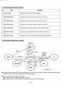
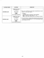
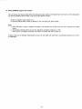
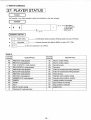
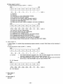
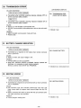
SETUP OPERATION
SETUP functions are the initializing functions of the unit, ex. Communication Mode, Automatic Start, Alternate Control, White
Flag Response
etc.
Settings are performed via the On-screen indicator.
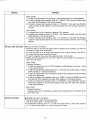
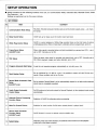
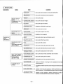
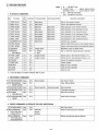
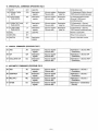
1. SET ITEMS
No.
ITEM
CONTENT
1 Communication Mode Setup
RS-232C, RS-422A computer interface set up communication speed, parity,
fer format.
2
Beep Sound Setup
On/Off set up for beep sound for button input feed back.
3
White Flag Control Setup
On/Off, to control playback of White Flag recorded frame as the first frame of picture
at still playback time. When 2-3 pull down is effected, picture is played back, set to on.
4
Frame Servo Setup
[LQ-3031Tonly]
When video signal is recorded (when not field controlled by a general use VCR,
set to OFF. Normally set to ON.
5
TBC Setup
When big skew video signal is recorded and played back, set to OFF, Normally set to
ON. When playback images are badly distorted, set to OFF.
6
Program Automatic Start Setup
It sets the unit executes program automatically or not with power ON.
7
Deck Number Setup
Set up individual No. (0—99) for a unit. It is possible to select unit with On-line commands. Allows multiple units to be On-line.
Record Mode Automatic Clear
8 Setup
[LQ-3031Tonly]
etc. trans-
etc.),
Set up whether Record Mode is to be automatically cleared or not after entire reserved
record area is completely recorded.
Audio Output Automatic
Control Setup
On/Off functions to limit audio output for Normal Playback, in other playback mode mutes
automatically.
10
Alternate Picture Processing
Function Setup
Selection of On/Off for alternate picture processing.
11
Mute For Erased Picture
Selection for mute function On/Off when erased picture is played back.
12
Record Area Guarantee
Function Setup
[LQ-3031Tonly]
On/Off function to ensure a desired record available area.
13
System Setup
Selection of the auto online function, the external control function and the playback
mode (with a time base corrector).
9
25
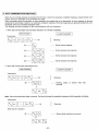
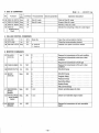
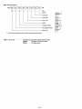
2. BUTTON FUNCTION IN SETUP MODE
No.
CONTENT
ITEM
1
SETUP button
Set/Reset of SETUP mode (toggle operation).
2
FWD. SCAN button
Changes menu (when pressed, changes over to next menu).
3
REV. SCAN button
Changes menu (when pressed, returns to previous menu).
4
FWD. STEP button
Changes set up item (when pressed, changes to next item).
5
REV. STEP button
Changes set up item (when pressed, returns to previous item).
6
FWD. PLAY button
Changes set up content (when pressed, changes to next figure).
7
REV. PLAY button
Changes set up content (when pressed, changes to previous figure).
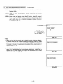
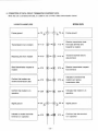
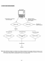
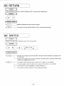
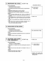
3. SETUP MODE CONDITIONAL CHANGE
POWER ON
DISC LOAD
ID WRITE*
ID READ
ERASE*
ID
AUTOMATIC RETURN
REC MODE*
RUN
ERASE REC MODE*
MODE
PLAY
STILL
X
"""^SSLOW
(
ERASE
j
. LQ-3031Tonly
As shown in above diagram, SETUP button is effective only when in the Off-line Mode, and Eject, Stop and Playback Modes.
When SETUP button is pressed, it toggles SETUP mode set up/clear.
When in SETUP mode, unit operates as follows.
Address indication mute; Operating mode does not change.
Note: Playback SETUP and Rec. SETUP are possible to set up by the On-line command.
-26-
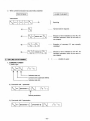
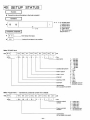
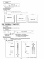
4. SETUP LEVEL
MAIN MENU
RS-232C SETUP
MENU
(COMMUNICATION
MODE MENU)
CONTENT
ITEM
MENU
i— XON/XOFF
(Set up the communication control with XON/XOFF)
— BAUD RATE
(Set up the transmission/receiving speed)
— PARITY
(Set up the parity)
CHARACTER LENGTH
(Set up the character length)
STOP BIT
(Set up the stop bit number)
— CONTROL TYPE
PROGRAM SETUP
MENU
(PROGRAM MENU)
THE SETUP
MENU
(MAIN MENU)
PLAYBACK SETUP
MENU
(PLAYBACK OPTION
SETUP MENU)
REC. SETUP MENU
(RECORD OPTION
SETUP MENU)
[LQ-3031Tonly]
SYSTEM SETUP
MENU
(Selection of RS-232C control type)
DECK NO.
(Set up the deck number)
AUTO START
(Set up the program auto start)
RUN PROGRAM
(Selection of run program)
i—BEEP
(Set up the button input confirmation sound)
— WHITE FLAG CTL.
(Set up the White Flag control)
(Set up the TBC control)
TBC
— AUDIO CTL.
(Set up the audio output automatic control)
— ALTERNATE CTL.
(Set up the alternate picture process function)
•— ERASED FRAME
(Set up the erased picture mute function)
i— AUTO MODE CLEAR
(Set up the record mode automatic clear function)
FRAMING SETUP
(Set up the framing servo function)
•— RANGE GUARANTEE
(Designated record area guarantee function)
r- AUTO ONLINE
(Setup of function of turning into the selected On-line mode
when power on.)
-
EXT.CTL(l/0)
(On/Off for external control function through I/O terminal for the
unit.)
- STILL (EXT.TBC)
(Setting of still and step playback, whether performed by one
field or one frame. The dedicated time base corrector is requied.)
SLOW (EXT.TBC)
•27-
(Setting of slow playback, whether performed by fields or
frames. The dedicated time base corrector is required.)
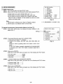
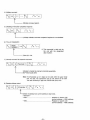
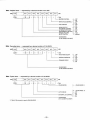
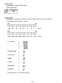
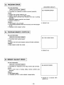
5. SETUP PROCEDURE
THE SETUP MENU
1. RS232C
2. PROGRAM
3. PLAYBACK
4. RECORDING
5. SYSTEM
CHANGE MENUS
CHANGE ITEMS
SET PARAMETER
[1 ] SETUP mode set up
STEP 1. Press SETUP button and enter SETUP mode.
STEP 2. When in SETUP mode, the following On-screen display appears [Fig. 6].
• SCAN buttons are used to change menus as 1 - 5.
• STEP buttons are used to change items within each menu.
• PLAY buttons are used to change set up content of each item.
When the menu is selected, it is also possible to press the number
buttons and directly select.
Note:
1. SETUP button is effective only in Eject or Playback condition.
2. SETUP button is not effective while in On-line mode.
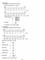
RS-232C Asynchronous Communication Mode set up (from |T|)
STEP 1. Press FWD. SCAN button, the following On-screen indication is displayed. [Fig. 7]
Blinking-
STEP 2. Transmission/Receiving speed set up (BAUD RATE).
1) This can be set when " 1 " is blinking.
2) Possible set up speeds: 300, 600, 1200, 2400, 4800, 9600, and
19200.
Change is made by pressing FWD. PLAY button or REV. PLAY
button.
If FWD. PLAY button is pressed, transmission and receiving speed
is increased, and if REV. PLAY button is pressed, speed rate is
reduced.
[Fig. 6]
*
"4. RECORDING" is LQ-3031T only.
RS232C SETUP MENU
»'»
;ikBAUDRATE
PARITY
CHARACTER LENGTH
STOP BIT
CONTROL TYPE
XON/XOFF
DECK NO
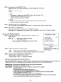
STEP 3. Parity set up (PARITY)
Select Item 2 with STEP button and select one of the following with PLAY button.
• No parity check
• Even parity
• Odd parity
NONE
EVEN
ODD
STEP 4. 1 character length set up (CHARACTER LENGTH).
Select Item 3 with STEP button, and select one of the following with PLAY button.
• Character length 7 bits
• Character length 8 bits
7
8
STEP 5. Stop bit set up (STOP BIT).
Select Item 4 with STEP button and select one of the following with PLAY button.
• Stop bit 1 bit
•Stop bit 2 bits
1
2
-28-
— SCAN
— STEP
— PLAY
[Fig- 7]
1200
EVEN
7
2
1
OFF
00
STEP 6. Control type set up (CONTROL TYPE).
Select Item 5 with STEP button and select one of the following with PLAY button.
• Type 1
• Type 2
1
2
1) Type 1:
• Transmission is possible only when DSR/CTS line is ON (more than +3V).
• Indicates receiving is possible with RTS, DTR.
(When both are ON, receiving is possible).
2) Type 2:
• When CTS line is OFF, set RTS line to ON. Then when CTS line is ON, transmit.
• RTS line is used for request to transmit.
STEP 7. XON/XOFF protocol set up (XON/XOFF).
This is the On/Off for communication control function. It is effective when program is being loaded.
STEP 8. Deck number set up (DECK NO.).
Select Item 6 with STEP button and set up 0 - 9 9 with PLAY button.
When deck No. is at beginning of the command, only the command of the unit of that number is accepted.
{3} Set up for PROGRAM execution
STEP1. Press FWD. SCAN button, and following On-screen indication is displayed. [Fig. 8]
Note: • 0
RAM program (loaded via On-line)
• 1—4
Option ROM program
>K Only one program can be loaded from On-line in RAM.
PROGRAM SETUP MENU
1 AUTO START
2 RUN PROGRAM
OFF
* 0: PLAYBACK TEST
1: Program 1 file name
2:
2
3:
3
4: Program 4 file name
[Fig. 8]
"PLAYBACK TEST" program in
RAM is loaded at time of shipment
for DEMO program.
STEP 2. Program Auto Start set up (AUTO START).
• ON
• OFF
When power is ON, program automatically executes.
Executes program by remote controller's button or On-line command.
STEP 3. Execution program designation (RUN PROGRAM No.).
Select program to execute with PLAY button.
To select program number, " * " (asterisk) is attached.
• Instruction on how to stop internal program execution
When the AUTO START is enabled (set to "ON") the unit will automatically execute one of the programs which are loaded on the
interface card of the unit. If it is necessary to stop the program execution, follow one of the following procedures:
Remote Control: Press execution PROGRAM RUN key and program will be stopped.
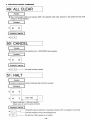
On-Line Control: Transmit the "AC" (All Clear) command.
Manual Method: This method can be used when no computer or remote control is available.
1. Turn the power off.
2. While holding SETUP key down turn the power on.
Hold the key until the SETUP MENUS appear on the screen.
3. Follow the instructions for PROGRAM SETUP in the Operating Instructions. The AUTO START
should be disabled by switching it to "OFF.
4. Press SETUP key to clear the setup mode, and turn the power off.
5. Turn the power on again. The program will not run until PROGRAM RUN key on the remote is pressed
or the unit receives the ON-LINE command "RN" (program run).
-29
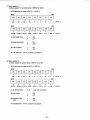
[4] Playback option set up
STEP1. Press FWD. SCAN button, and following On-screen indication is disPlayed
'
[Fi9
'
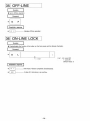
9]
Blinking-
PB SETUP MENU
*1*BEEP
2 WHITE FLAG CTI
3 TBC
4 AUDIO AUTO CTL . .
5 ALTERNATE CTL . . .
6 ERASED FRAME
. ON
OFF
ON
ON
OFF
ON
[Fig. 9]
STEP 2. Button input feed back sound set up (BEEP).
Set up of On/Off of button input feed back sound.
• ON
• OFF
Output button feed back sound.
No output.
STEP 3. Set up of picture head field change control via White Flag (WHITE FLAG CTL).
When in Still or Step Playback, it plays back white flag field at the picture starting field.
• ON
• OFF
Performs control based on white flag.
Does not perform based on white flag.
Note: White flag used to convert 24 FPS. to 30 FPS. (2-3 Pull Down).
STEP 4. Time Base Correction function set up (TBC).
When the unit plays back many skewed video, which is recorded from VCR, this is set to OFF.
Normally set to ON.
• ON
• OFF
Performs TBC control.
Does not perform TBC control, at this time Gen Lock is also OFF.
Note: We discourage recording from RAW VCR output.
Any VCR source should be put through an external TBC before recording.
STEP 5. Audio output automatic control set up (AUDIO AUTO CTL).
Change of audio output control methods, when in playback of frame audio is recorded to.
• ON
• OFF
Only FWD, PLAY outputs Audio.
Audio outputs in all playback modes.
Note: When audio mute is designated by command, mute always functions.
STEP 6. Alternate picture processing function set up (ALTERNATE CTL).
When purpose is to chain from erased frame address to frame address of re-recorded frame (alternate picture
address), this set up determines if alternate picture address is searched or not.
• ON
• OFF
Alternate picture address is searched.
Alternate picture address is not searched.
STEP 7. Erased picture mute control set up.
• ON
• OFF
Playback of erased frame.
Erased frame is muted during playback.
-30-
Record option set up [LQ-3031Tonly]
STEP1. Press FWD, SCAN button, and following On-screen indication is displayed. [Fig. 10]
Blinking •
REC SETUP MENU
I
-VAUTO MODECLEAR
2 RANGE GUARANTEE
3 FRAMING SERVO
ON
OFF
ON
Note: When the unit is to be controlled by program built for TQ-2026F control
use, set to following.
• AUTO MODE CLEAR
ON
• RANGE GUARANTEE
OFF
[Fig. 10]
STEP 2. Set up of record mode automatic clear function (AUTO MODE CLEAR).
Set up of function to automatically clear the Record Mode when possible record frames are reduced to 0.
(After reserved record range is recorded).
• ON
• OFF
.Automatic clear
a) When On-line, transmit "CS" when clear.
b) After clearing, playback the last frame recorded.
.Cleared by command (clearing method is selectable)
a) When cleared by REC MODE button or "CS" command, it plays back the last frame recorded.
b) If cleared by forward direction playback command (or button) ie, FWD. PLAY, playback is from starting
frame recorded.
(review function)
c) If cleared by reverse direction playback command (or button) ie, REV. PLAY, playback is from last
frame recorded.
STEP 3. Recording area guarantee function (RANGE GUARANTEE).
• ON
• OFF
Keep searching area until designated number of frames is guaranteed.
Even if designated area is not guaranteed, this function guarantees closest non-recorded area as the
recording area.
STEP 4. Framing servo set up (FRAMING SERVO).
• ON
• OFF
Records only video signal which is frame controlled.
Records video signal which is not frame controlled.
Gen Lock function does not operate.
Note: If video signal without equivalent pulse (when it is not an NTSC signal) or sync signal is input, this may not
operate properly, even though the framing servo is ON.
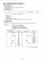
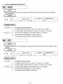
[6] SYSTEMS SETUP
SYSTEM SETUP MENU
1.AUTOONLINE
2.EXT.CTL (I/O)
3.STILL (EXT.TBC)
4.SLOW (EXT.TBC)
OFF
ON
FRA
ODD
-31 -
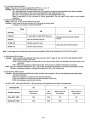
1) On-Line Auto Resume Function
Setup: Press H or t i l key and select from OFF to 0, 1, 2, 3... 15.
Function: OFF: When power on, the unit is NOT in On-line.
ON—When the power is turned off while the unit is online, it will resume online operation when power is restored.
[0] to [15]: When power on, the unit is in the selected On-line mode (mode 0-15).
[0] to [15]—Turning power off in online mode turns it on in this selected online mode.
Refer to description on ON Command in Online Specification. Set the proper online mode for your software
application.
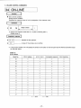
2) External Control Functions
Setup: Press B o r H key and select ON, or OFF.
Function: Switch a part of the port functions of I/O terminals as shown below.
In program run, however, it will be forced OFF.
~^-~_^
Port (I/O)
Mode
ON
^ ~ \ ^ ^
OFF
11 (Pin 4)
1 frame REC or FWD STEP when low
10 (Pin 3)
REC or FWD PB while low
01 (Pin 12)
Monitor output of 11 port
O0(Pin11)
Monitor output of 10 port
General purpose input (GE command
control)
Output Port (PU command control)
Note: A short beep sound is heard at the start of record or playback. Refer the pin assignment of I/O terminal to page 47.
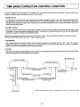
3) Still (External TBC) Function
Function: After connecting the dedicated time base corrector (refer to page 45-46), set still and step playback whether
performed by one field or one frame.
[FRA]: Still and step playback is performed by frame. Set the FRA mode if the dedicated time base corrector is not
connected.
[FIE]: Still and step playback is performed by field. In this mode, no vibration of still picture can be seen.
Note: After FIE is selected, each time the @ o r @ button is pressed, the still picture is reversed or advanced by one field.
Therefore, the playback address is changed by pressing the @ o r @ button twice.
4) Slow (External TBC) Function
Function: After connecting the dedicated time base corrector (refer to page 45-46), set slow playback whether performed by
one field or one frame.
[ODD]: Slow playback of 1st field of each frame is performed.
[O/E]: Slow playback of 1st field and 2nd field alternately is performed.
[FRA]: Slow playback is performed by frame.
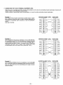
Set STILL (EXT. TBC) and SLOW (EXT. TBC) according to the playback picture. Refer to the table below.
Dedicated TBC
No
Yes
Content of picture
Motion picture/
Still picture
Still
picture
Motion pitcure at
lower speed
Motion picture at
higher speed
STILL (EXT. TBC)
FRA
FRA
FIE
FIE
SLOW (EXT. TBC)
FRA
FRA
ODD
O/E
32-
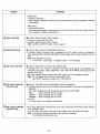
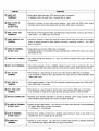
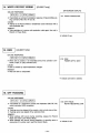
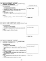
PLAYBACK METHODS
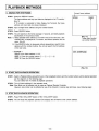
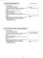
1. SEARCH FOR THE FRAME
Current frame address
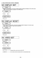
STEP1. Press the DISPLAY button.
The frame address and any input data are displayed on the TV monitor.
[Fig.11]
If TV monitor is connected to Video Display Out Terminal, the frame
address and input data are always displayed.
D00001
A12345
STEP 2. Input a target frame address using the number buttons.
STEP 3. Press SEARCH button.
STEP 4. The unit searchs to the frame (average 0.7 second), and starts playback
automatically in the previous mode.
Note: 1) When selected frame address is not within limits of the user area, "E01
OVERFLOW" is displayed on TV monitor, and search operation will not
occur. [Fig. 12]
2) If the SEARCH button is depressed without designating a specific frame
address with the number buttons, the unit will search the first address
of the user area.
< Example >
Search to the frame address "1115"
STEP 1. Press the number buttons ©
STEP 2. Press the SEARCH button.
[Fig. 11]
Target data inputted
via number buttons
®-<D
[Fig. 12]
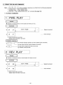
2. START THE PLAYBACK OPERATION
STEP 1. Select a Playback Mode using which ever of the 8 playback buttons and the number buttons suit the desired operation
per the diagrams on the following page.
You can select from 10 modes of playback operations.
STEP 2. The unit starts playback in the selected mode.
Note: Slow Mode can be effected only by using an Optional Remote Controller.
However, slow motion can be effected by use of the forward or reverse step technique, (see following page)
3. STOP THE PLAYBACK OPERATION
STEP1. Press FWD. STILL/STEP button or REV. STILL/STEP button.
STEP 2. The unit stops the playback operation and displays the still frame at the current address.
33-
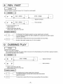
CHOICE OF THE PLAYBACK OPERATION
PLAYBACK MODE
OPERATION
BUTTONS
FWD. PLAY
FORWARD PLAY
• When this button is pressed, the unit starts forward/reverse
playback at normal speed (30 frames/sec).
• Audio playback is available only in the forward play mode.
REV. PLAY
REVERSE PLAY
NUMBER BUTTONS
+
FORWARD FAST PLAY
FWD. PLAY
NUMBER BUTTONS
+
REVERSE FAST PLAY
REV. PLAY
NUMBER BUTTONS
(if neccessary)
FORWARD STEP
+
FWD. STEP
! ! •
NUMBER BUTTONS
(if neccessary)
REVERSE STEP
+
REV. STEP
*4II
From 1 to 10 times normal speed forward/reverse may be selected
via the number buttons.
After input of the desired speed rate, press FWD. PLAY/REV. PLAY
button.
< Example >
5 times normal speed forward (150 frames/sec.)
STEP 1. Press the number button © .
STEP 2. Press FWD. PLAY button.
• Press this button to enter the Step/Still Mode.
Present frame will be played back in Still Mode.
(This does not harm the disc in anyway.)
1
If button is hold depressed, the unit will shift after a few seconds
to 4 frames per second Step Playback.
Interval speed may be selected via the number buttons between
1 to 256 seconds.
< Example >
Display each frame for 30 seconds forward.
STEP 1. Press the number buttons (f) -» © .
STEP 2. Press FWD. STEP button.
FWD. SCAN
FORWARD SCAN
M
REV. SCAN
REVERSE SCAN
• When this button is pressed, On-screen scanning is obtained at a
rate of approx. 1500 frames per second. (Gen Lock will be disable.)
• SCAN buttons may be pressed during other playback modes. When
this button is released, the unit automatically returns to the forward
play mode.
LKI
-34-
PLAYBACK MODE
OPERATION
BUTTONS
NUMBER BUTTONS
(if neccessary)
+
FORWARD SLOW
From 1/2 to 1/256 times normal speed, forward/reverse, may be
selected via the number buttons.
FWD. SLOW
< Example >
1/10 normal speed (3 frame/sec.) forward playback.
STEP 1. Press the number buttons © -* ®.
STEP 2. Press FWD. SLOW button on the Remote Controller.
(on the remote controller)
NUMBER BUTTONS
(if neccessary)
+
REVERSE SLOW
REV. SLOW
1
If the SLOW button is pressed without designating slow speed with
a number input. Slow Playback at 1/3 the normal playback speed
will be effected (10 FPS).
(on the remote controller)
-35-
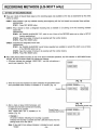
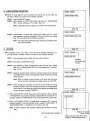
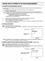
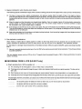
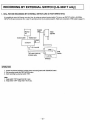
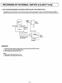
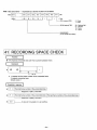
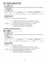
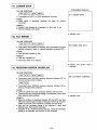
RECORDING METHODS [LQ-3031T only]
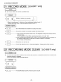
1. SETTING OF RECORIDNG MODE
There are 3 kinds of Record Mode based on the recording space area available on the disc as ascertained by the check
method as below.
CASE 1 : When desired to get any available recording area beginning with the first (lowest) non-recorded frame address.
[OPERATION]
STEP 1. Press REC MODE button.
CASE 2: When desired to check a designated recording area is available or not starting at the first recording available
space area.
[OPERATION]
STEP 1. Set 'RANGE GUARANTEE' OFF, which is one of items of the RECORD option set up (refer to SETUP
function specifications).
STEP 2. Input the number of frames to be recorded with the number buttons.
STEP 3. Press REC MODE button.
CASE 3: Guarantee the designated record area.
[OPERATION]
STEP 1. Set 'RANGE GUARANTEE' (verify frames requested are available to record) ON, which is one of items
of the RECORD option set up.
STEP 2. Input the number of frames to be recorded with the number buttons.
STEP 3. Press REC MODE button.
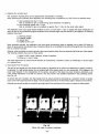
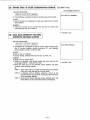
After setting Record Mode according to one of the above mentioned operations, the LED indicator on REC MODE button
will light, and the On-screen display will indicate the following:
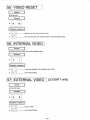
1. On-screen indicates the message "VIDEO REC", and the unit performs a
IA123451
record area inspection. [Fig. 13]
VIDEO REC.
[Fig. 13]
2. When the record area inspection has been completed, the guaranteed record
area (recordable frame number) is indicated on TV monitor. [Fig. 14]
Current frame
3. After a check at about 2,500 frames/sec. and
the blank area has been scanned and recording
is determined to be possible.
Then "VIDEO REC. OK" is indicated on TV
monitor. [Fig. 15]
<-|A12345| |R01000h*-
VIDEO REC.
Guaranteed
record area
[Fig. 14]
Guaranteed record area
Current frame
(recording start frame)
HA12345I |R01000h«-
VIDEO REC. OK
< Example >
On-screen indication indicating that recording is possible.
Indicates that recording is possible and that 1,000 blank frames from the
starting frame of the disc side A.
Note: If disc side B, then address indication is indicated as such, example
"B1000".
_36[Fig. 15]
2. AUDIO RECORD SELECTION
A12345
When an audio signal is to be recorded at the same time as the video, set
the Record Mode, then perform the following operation.
R0100QJ
AUDIO/VIDEO REC.
STEP1. Press AUDIO REC button.
STEP 2. LED indicator on AUIDO REC button will light, and "AUDIOA/IDEO
REC." will be indicated on TV monitor. [Fig. 16]
Note: AUDIO REC button is effective only when in the Record Mode.
[Fig. 16]
A12345
STEP 3. Approximately 1 second after pressing this button, and if a record
area inspection has been completed, On-screen indication will change
[Fig. 17], and indicate that recording is possible.
R01000
AUDIO/VIDEO REC. OK
Note: The delay times mentioned above should be considered when
in the On-line Mode.
3. RECORD
[Fig. 17]
As indicated in [Fig. 15] or [Fig. 17], the On-screen message indicates a "recording possible" condition. Record according to the following operation:
A12401
R00100U-
VIDEO REC. IN
STEP 1. Input recording frame number with the number buttons.
Residual
recording frame
number
STEP 2. Press REC. START/STOP button.
STEP 3. LED indicator on REC. START/STOP button will light and "VIDEO
REC. IN" or "VIDEO/AUDIO REC. IN" will be indicated on TV monitor.
[Fig. 18, 19]
STEP 4. Residual recording frame number is indicated instead of the residual
recordable frame number, and designated number of frames are going
to be recorded.
[Fig. 18]
| A124011 |R00100|
VIDEO/AUDIO REC. IN
Note: When a number of record frames is not input, only one frame
will be recorded. Recording of multiple frames is at 30 FPS.
STEP 5. When recording is completed, unit returns to the previous recording
possible condition at the next recording start frame. If the guaranteed
record area is 0, the following occures; (the residual recordable frame
number becomes example "R00000").
[Fig. 19]
A12500
1) When 'AUTO MODE CLEAR' (auto clear function setting of Record Mode)
of 'RECORDING' (record option setting) of Setup Mode is selected ON, recording is cleared, and Still Playback in the last recorded frame is performed.
R00000-—
VIDEO REC
2) When 'AUTO MODE CLEAR' of Setup Mode is selected OFF, recording
possible condition in the last recorded frame is cleared ("VIDEO REC." or
"AUDIOA/IDEO REC." is indicated on TV monitor). [Fig. 20]
Note: In order to perform next operation, clearing Record Mode is neccessary.
Last recorded frame address —•
-37-
[Fig. 20]
Residual recordable
frame number
When selected Audio REC. Mode
indicates "VIDEO/AUDIO REC."
4. CLEARING RECORDING MODE
There are 3 ways to clear the recording mode, generally classified as follows:
CASE 1 : Clearing with REC MODE button.
[OPERATION]
STEP 1. Press REC MODE button.
STEP 2. LED indicators on REC MODE button and on AUDIO REC button go out, Record Mode is cleared, then
Still Playback in the last recorded frame is performed.
CASE 2: Clearing with forward direction playback button example FWD. PLAY, (review function)
[OPERATION]
STEP 1. Press FWD. PLAY or FWD. STEP or FWD. SLOW (on the Remote Controller).
Note: It is possible to input playback speed with the number buttons, before pressing these playback
buttons.
STEP 2. LED indicators on REC MODE button and on AUDIO REC button go out, and Record Mode is cleared,
then playback action of each button from the first recorded started frame is performed.
[Example] Clearing with FWD. PLAY
REC.
SEARCH
REC. START FRAME
REC. END FRAME
FWD. PLAY
CASE 3: Clearing with backward direction playback button example REV. PLAY.
[OPERATION]
STEP 1. Press REV. PLAY or REV. STEP or REV. SLOW button.
Note: It is possible to input playback speed with the number buttons, before pressing these playback
buttons.
STEP 2. LED indicator on REC MODE button and on AUDIO REC button go out, and Record Mode is cleared,
then playback action of each button from the last recorded frame is performed.
[Example] Clearing with REV. PLAY
REC.
REC. START FRAME
REC. END FRAME
REV. PLAY
38-
DISC ID (RECORD/PLAYBACK METHODS)
1. DISC ID FUNCTION
Disc ID numbers are 5 digit numbers from 0—99999, which can be recorded on one side of the disc.
Rewriting the disc ID number is possible 9 times only.
2. DISC ID NUMBER READING METHOD
STEP1. Press ID/ALTERNATE CORD READ button (READ button) on the Remote Controller in Playback Mode.
STEP 2. The unit mutes the On-screen picture and reads the disc ID number.
When completed it performs Still Playback at the first frame of the user's define area, and displays read disc ID
number On-screen as indicated in [Fig. 21].
Current frame
/the first frame of
vthe user's define area
Number of
times written
Disc ID number
[Fig. 21]
(Disc ID number was written
once, and the ID was 12345)
When no disc ID number has ever been written, On-screen indication is
as follows. [Fig. 22]
I
ID-R01- * * * * *
i
i
indicates no ID \
was ever written/
[Fig. 22]
Note: If disc ID number cannot be read due to disc dirt
etc., error
message "E45 READ ERROR" is indicated on TV monitor.
[Fig. 23]
E45 READ ERROR
[Fig. 23]
39-
3. DISC ID NUMBER WRITING METHOD]
[LQ-3031Tonly]
STEP 1. Input disc ID number with the number buttons in Playback Mode.
STEP 2. Press ID/ALTERNATE CODE WRITE button (WRITE button) on the Remote Controller.
STEP 3. Mutes screen and writes disc ID number.
When completed, Still Playback is performed at the first frame of the
user's define area, then displays completion message On-screen as indicated in [Fig. 24].
Current frame
The 2nd time a disc
ID number was written
as 12345
[Fig. 24]
Note:
1. When attempting to define disc ID number a second time, disc ID
number is not written, instead the error message "E43 DUPLICATE
DEF." is indicated on TV monitor. [Fig, 25]
E43 DUPLICATE DEF.
When the disc ID number is to be changed, the current disc ID number
is erased then the new disc ID number is written.
[Fig. 25]
2. If the disc ID number was written incorrectly, the error message "E41
WRITE ERROR" is indicated on TV monitor. [Fig. 26]
3. Notes 1 and 2 are executed by performing Still Playback at the first
frame of the user's define area.
E41 WRITE ERROR
[Fig. 26]
-40-
4. DISC ID NUMBER ERASING METHOD
[LQ-3031Tonly]
STEP1. Input a 5 digit disc ID number with the number buttons while in the
Playback Mode.
STEP 2. Press ID CODE ERASE button (ERASE button) on the Remote
Controller.
STEP 3. Mutes screen and erases current disc ID number, (about 10 seconds)
When completed, Still Playback is performed at the first frame of the
user's, define area, and a completion message is displayed On-screen
as indicated in [Fig. 27].
Current frame
Disc ID number
" # " indicates that it
was not written
[Fig. 27]
Note:
1. When the input disc ID number and the disc ID number of disc are different,
it does not erase and Still Playback is effected at the first frame of the user's
define area. And the error message "E44 BAD ID NUMBER" is indicated on
TV monitor. If the disc ID number cannot be read correctly, a new number can
be designated. [Fig. 28]
2. The maximum number of disc IDs that can be written is 10. If a designation
above 10 is attempted then the error message "E42 OVER TIMES" will be
displayed on TV monitor and the unit will go to the Still Mode at the first frame
of the user's define area. [Fig. 29]
E44 BAD ID NUMBER
[Fig. 28]
E42 OVER TIMES
[Fig. 29]
-41-
ERASE AND ALTERNATE PICTURE MANAGEMENT
1. ALTERNATE PICTURE MANAGEMENT FUNCTION
This function executes the following actions by writing the alternate picture address information to the recording finished frame.
1) Erased function:
The frame written alternate picture address (called erase frame) mutes at playback time.
2) Alternate picture management function:
When above mention erased frame is searched, it automatically searches the frame to the alternate picture address.
Note: The action of 1) and 2) make ON/OFF possible, and perform the function setting in each following items on the
PLAYBACK MENU (playback option setting) in the SETUP function.
1. ERASED FRAME (erased picture mute control setting)
2. ALTERNATE CTL. (alternate picture processing function setting)
For details, refer to "SETUP OPERATION".
*1
*2
*3
Reading and writing of alternate picture address information is performed in Erase Mode.
The alternate picture address information can be written once per frame.
Erase or changing of this information is not possible.
The frame alternate picture address information is written once, it is treated as a completed record frame during the
video non-recorded area inspection time.
2. SETTING OF ERASE MODE
STEP1. Press ALTERNATE button in Playback Mode.
STEP 2. Erase Mode is invoked and, On-screen indication is displayed (as in [Fig. 30]), and Still Playback is performed in
current frame being played back.
Current frame
Indicates Erase
Mode is set
[Fig. 30]
Note: When Erase Mode in the non-recorded frame is attempted, the error message "E09 UNRECORDED FRAME" is displayed on TV monitor, and Still Playback at that frame is performed.
3. WRITING ALTERNATE PICTURE ADDRESS INFORMATION (ERASE OF FRAME)
[LQ-3031T only]
STEP 1. Input alternate picture address with the number buttons in the Erase Mode.
STEP 2. Press ID/ALTERNATE CODE WRITE button on the Remote Controller.
STEP 3. Alternate picture address information is written in frame performing Still Playback, then reads the alternate picture
address information in frame, then displays it on TV monitor as in [Fig. 31].
Current frame
ALT.CODE 12345
i
Indicates written alternate
picture address is 12345
[Fig. 31]
-42-
Note: When ERASE FRAME is OFF in SETUP (erased frame mutes playback)
the screen is muted after this code is written.
When ERASE FRAME is ON, the erased image is displayed on TV
monitor in a set up format. [Fig. 32]
|A10000| | ERASED |
[Fig. 32]
Note: 1. When write protect is set, no data is written and the error message
"E11 WRITE PROTECTED" is indicated on TV monitor. [Fig. 33]
E11 WRITE PROTECT
[Fig. 33]
2. When the alternate picture address was previously written, no data is
written and the error message "E43 DUPLICATE DEF." is indicated
on TV monitor. [Fig. 34]
E43 DUPLICATE DEF.
[Fig. 34]
When a disc rotation sync, abnormality has occurred, the error message "E07 VIDEO IN NORMAL? OR SYNC IN NORMAL?" is indicated
on TV monitor. [Fig. 35]
E07 VIDEO IN NORMAL?
OR SYNC IN NORMAL?
[Fig. 35]
When the written alternate picture address was written incorrectly upon
verification (read after write), the error message "E41 WRITE ERROR"
is indicated on TV monitor. [Fig. 36]
E41 WRITE ERROR
In this case, rewrite the same alternate picture address with the
number buttons, and press ID/ALTERNATE CODE WRITE button
again.
[Fig. 36]
-43-
5. When the alternate picture address which was input with the number
buttons is not in the user's define area, no data is written and the
error message "E01 OVERFLOW" is displayed on TV monitor.
[Fig. 37]
E01 OVERFLOW
[Fig. 37]
4. READING OF ALTERNATE PICTURE ADDRESS INFORMATION
STEP1. Press ID/ALTERNATE CODE READ button (READ button) on the
HA10000
Remote Controller.
STEP 2. Read alternate picture address information of frame in Still Playback, and
indicate it on TV monitor as in [Fig. 38].
Current frame
ALT. CODE 12345
The alternate pictureaddress of this frame
is 12345.
[Fig. 38]
Note:
1. When an error has occurred concerning the reading of alternate picture
address information, the error message "E45 READ ERROR" is displayed
on TV monitor. [Fig. 39]
E45 READ ERROR
[Fig. 39]
2. When a disc rotational sync abnormality has occurred, the error message
"EOT VIDEO IN NORMAL? OR SYNC IN NORMAL?" is displayed on TV
monitor. [Fig. 40]
E07 VIDEO IN NORMAL?
OR SYNC IN NORMAL?
[Fig. 40]
5. CLEARING ERASE MODE
1. When ALTERNATE button is pressed, Erase Mode is cleared, and Still Playback occurs at the current frame.
2. If the playback button is pressed (FWD. PLAY, REV. PLAY, FWD. STEP, REV. STEP, FWD. SLOW, or REV. SLOW) Erase
Mode is cleared, and the Playback Mode is pressed executed.
3. When the EJECT button is pressed, Erase Mode is cleared and the disc is ejected.
-44-
TIME BASE CORRECTOR CONTROL FUNCTION
LQ-3031T/LQ-3032T can be connected to an external TBC (Time Base Corrector)/Frame Synchronizer. When connected to the
equipment as outlined below the following functions can be enabled:
• Seamless Search
The still image of the current frame will be retained when the player engages the search mode. After the optical head searches the
new target frame, the memory in the TBC is refreshed and the new image is displayed on the monitor. This function is referred to as
Seamless Search because the output of the TBC does not cut to black during search time, but keeps the previous image on the
screen during the search mode.
• Field Still, Fine Slow
Since each TV frame is mode from two independent TV fields, flicker will sometimes appear on the screen when fast motion images
are recorded. To counter this negative image artifact there is a provision for successive field playback with this TBC interface card.
This effect is available in the slow and still playback modes.
Please connect according to the figure, and set the "3 STILL (EXT. TBC)" in the SYSTEM SETUP MENU of the SETUP function to
"FIE" and "4 SLOW (EXT. TBC)" to the "O/E" or "ODD". (Refer to page 32.)
• Field Still Mode
After a frame is searched only the first field of that frame will be played back. Then each time the @
or the S
button is
pressed, the still picture is advanced or retarded only one field at a time (not and entire frame). When this function is activated the
pictures on the screen will be displayed without annoying vibration.
• Fine Slow
When the unit is placed in the slow playback mode (1 /2 speed or less) playback is performed one field at a time. This function assures
ultra-smooth slow-motion playback without picture vibration.
Color Monitor TV
LQ-3031T/LQ-3032T
Time Base Corrector
To RS-232C
Terminal
To EXT SYNC IN To ADV SYNC
Coaxial cable
To VIDEO OUT
Coaxial cable
" T o VIDEO
IN
To VIDEO IN
To VIDEO OUT
Coaxial cable
To I/O Terminal
Shielded
cable
TBC cable (optional)
To D-SUB 25 Pin Terminal
Shielded cable
Note: Please use each device complying with Part 15 of the FCC Rules.
Host Computer
-45-
Timing chart
FREEZE, FRAME/FIELD and ODD/EVEN signals from I/O terminal control a time base corrector as follows.
Signal output voltage . . . H i g h : High impedance
Low: 30 mV
output current . . . max: - 2 0 mA
"SR+10000:" c o m m a n d in
N
l=17msec
Video
Video mute
N+10000 N+10000
!=17msec
-4-
il1-l4msec
MUTE
11~14msec
FREEZE
FREEZE ON
at
Field
Still
at
Frame
Still
{
{
FRAME/FIELD
ODD/EVEN
FIELD
High
(former state)
Low
Low
FRAME/FIELD
ODD/EVEN
High
Fig. 1
SEARCH
"TF" command in "TF" command in
I Normal Play
"TF" command in
Video
N-1
N
HH
i11~14msec
FREEZE
STILL
N+1
TFNedSterjL
Hh
High
FIELD
FRAME/FIELD
ODD/EVEN
ODD
Fig. 2
ODD
Field STILL with field STEP
Normal "LF2:"command in
Play
Video at V<>
N-1
normal speed
11~14rnsec
EVEN
N
Slow (1/2 normal speed)
N+1
N
N+1
FREEZE
N+2
High
FRAME/FIELD
FIELD
11—14msec
11~14msec
ODD/EVEN
ODD
Fig. 3
EVEN
ODD
Slow (V2 normal speed)
-46-
EVEN
1
PIN ASSIGNMENTS OF TBC CABLE (OPTIONAL)
PIN ASSIGNMENTS OF TBC CABLE LV-K003 (OPTIONAL)
• Half pitch 20 pin connector (male)
connect to I/O terminal
1
13
10
n nn n n n n n n n
\
\
\
/
ooooooooooooo
oooooooooooo
/
u uu u uu u u u u
11
/
14
20
25
Pin No.
Signal
Pin No.
' D-SUB 25 pin connector (male)
connect to the dedicated time base corrector
Signal
1
FREEZE (TBC)
1
FREEZE (TBC)
2
FRAME/FIELD (TBC)
2
FRAME/FIELD (TBC)
3
10 (Input port 0)
3
10
4
11 (Input port 1)
4
11
5
12 (Input port 2)
5
12
6
13 (Input port 3)
6
13
7
14 (Input port 4)
7
14
8
15 (Input port 5)
8
15
9
16 (Input port 6)
9
16
10
17 (Input port 7)
10
17
11
OO (Output port 0)
11
GND
12
01 (Output port 1)
12
13
0 2 (Output port 2)
13
14
0 3 (Output port 3)
14
OO
15
0 4 (Output port 4)
15
01
16
05 (Output port 5)
16
02
17
0 6 (Output port 6)
17
03
18
0 7 (Output port 7)
18
04
19
ODD/EVEN (TBC)
19
05
20
GND
20
06
21
07
22
ODD/EVEN (TBC)
23
GND
24
25
-47-
VARIOUS MANUAL OPERATIONS
WHITE FLAG DETECTOR (Still Playback only)
1. The white flag is a signal (100% white peak) for inputting before the field to be played back so that each picture can be
played back correctly during Still Picture playback.
When a disc in which a white flag is entered is played back, the starting frame with the white flag is displayed.
2. White flag is convenient, as illustrated below, when 24 frames/sec. film is converted to 30 frames/sec. NTSC disc, for
example.
• Motion picture film (24 frames/sec.) converted to video signal (30 frames/sec).
Frame 3
Frame 2
Frame 1
Frame 4
Frame 5
Frame 6
DDDDDODDnDDDDODDDDDDDDDDDDnDDDD
Film
(24 frames/sec.)
:c
D C O D D D C D D D DC D D D D C D D D
P
Video
(30 frames/sec.)
\P
\.P
/
\
P \ P
N
^FieidVFieid^ ' ReidVFieid ^HeidYFieid^
OA2y
Frame 1
D D D DC D D D D
***"^.>"^P
'ReidVS^ 'fieidVField
N
'ReidVFieldN 'FieidN
OAky
Frame 2
Frame 3
Frame 4
Frame 5
Frame 6
Frame 7
The white flag inserter puts these white
flags in the vertical
interval of the master
tape:
Block diagram.
video
Mixer
video with
white flag
white flag
White Flan Incorter
Location of white flag.
On 18th or 281th line of the vertical interval of the video signal to be recorded.
Note: Set up the white flag before attempting this function.
-48-
LQ-3031T/LQ-3032T
RECORDING VIDEO SIGNALS SPECIAL INSTRUCTIONS [LQ-3031T only]
The following points require special attention when using a LQ-3031T to record video signals.
1. Standard Video signals
Please use standard video signals conforming to RS-170A. (See Fig. 41)
RS-170A specifies the following values,
Color subcarrier frequency:
Synchronizing signal amplitude:
Amplitude of video signal:
100
90
80
70
60
50
40
30
20
10
0
10
20
30
40
-
3.579545MHz ± 10Hz
0.286Vp-p
0.714Vp-p
-- --•
1 Vp-p
[}
u
}
IRE
SCALE
UNITS
[1r i g - 4 1]
M Dnito r shovving s tand a d sigrlal waveforrr
Attempting to record signals that differ substantially from standard signals may result in the problems indicated below.
2. Color subcarrier frequency
The color subcarrier frequency used should comply with the 3.579545MHz±10Hz specification described above.
Since standard signal generators are generally expensive, there may be cases where use of non-standard signals is unavoidable. In these cases, the error should be kept to within ±50Hz.
Color may be lost if the frequency differs substantially.
-49-
3. Adjusting the recording level
The LQ-3031T recording level can be adjusted both automatically or manually.
When recording with automatic level adjustment, the recording level is adjusted by an AGC circuit as specified below.
1) Input
Gain
2) Input
Gain
amplitude less than 1.1Vp-p
is controlled to give a synchronizing signal amplitude of 0.286Vp-p.
amplitude greater than 1.1Vp-p
is controlled to give an amplitude no greater than 1.1Vp-p for the whole video signal.
The amplitude of the input signal should therefore be set to no more than 1.1Vp-p. If signals with larger amplitudes are
input, the size of the synchronizing signal component of the recorded signal may be reduced. If this happens, the following
problems may result:
1)
2)
3)
4)
Wavering images
Distorted images
Vertical Jitter
Inability to Gen Lock
When recording manually, the amplitude of the input signal synchronizing signal is detected, and a green LED lights up
when the level reaches the standard value. Excessive inputs do not compress the synchronizing signal when the recording
level is controlled manually.
However, when recordings are made manually, there may be points where there are extremely high level input video signals.
The following problems may occur at these points.
1) Black or white "grass" distortion, similar to dropouts.
2) White-out, or loss of detail.
The output signal from the camera should therefore be monitored by a waveform monitor or oscilloscope, to set the signal
to a standard level.
4. Input signals from the camera
The level of input signals from the camera varies greatly by adjustment of the camera and differences in lighting conditions.
In particular, if a light shines directly into the camera, part of the camera input is a very strong light. If this happens, the
exact result depends on the characteristics of the camera, but parts of the signal may have excessive amplitudes, even
if the camera adjustment is set with an auto-iris. This may result in the problems described in the preceding section.
(See Fig. 42)
To prevent this sort of problem, the video signals from the camera should be monitored by a waveform monitor or oscilloscope, so that if the output becomes too large, it can be adjusted manually or the illumination angle or distance and be altered.
Particular care should be taken to control the input signal level if the recording is to be used as a master for taking copies.
IRE
100
-40
[Fig. 42]
Signal with areas of excessive amplitude.
50-
5. Special consideration when shooting small objects
The following special considerations apply when a camera is taking pictures of small object with a close-up lens or similar device.
(1) The type of close-up lense, lighting considerations and aperture greatly affect the depth of field. If the depth of field is
small, the parts that are not in focus appear blurred on the screen. This may produce color smear. One way of avoiding this is
increasing the lighting intensity to increase the depth of field. Another method is to raise the camera sensitivity and reduce the
aperture.
(2) When the object and the illumination are brought close together, there is a greater chance of the illumination entering the
camera directly or reflecting strongly into the camera lens. The camera output should be monitored carefully to adjust
the illumination untill a good output signal is obtained.
(3) If the background is while and is very close to the object, the color of the object may be reflected, coloring the background.
This can be avoided by moving the object and background further apart or by changing the background color so that the
reflected color is not obtrusive.
(4) Keep color saturation low. It provides a much better looking duplicate. Avoid recording images which have large amounts of
chroma which fall below 0 I.R.E. units.
6. Disc duplication considerations
When making a master disc for making copies be careful so time base errors and sync dropouts are not recorded into the
master; otherwise the duplicate will have the same errors, and they will tend to be magnified in the duplication process.
For this reason it is strongly recommended that a Time Base Corrector (TBC) be used to ASSURE quality recordings time after
time.1*11
1,11
Be sure to connect advanced vertical sync from the TBC when employing automatic frame duplication. This will assure frame
accurate duplication.
Also any playback source such as VCR or off air TV signal should be passed through a TBC or frame synchronizer to assure
quality recordings.
•
R E C O R D I N G F R O M A V C R [LQ-3031Tonly]
A. Direct recording from a VCR is possible, but
(1) The recording will be interrupted if a loss of video input is encountered.
(2) Time base errors will cause the image to waver or jitter upon playback (edit points are a good example). The disc will not
Gen Lock.
(3) Poor framing or poor sync on the source tape can cause random frames to be misrecorded or not recorded at all.
(4) Time base error from the tape will be impregnated into the disc; hence Gen Lock will be poor and copies will look terrible.
The examples cited here, and others, can cause only one field of the frame to be recorded; therefore the frame will be damaged
and unusable
the recorded check will detect the frame as blank but you will not be able to record there
the picture will blink on and off or be very unstable
and the Gen Lock function will be adversely affected.
-51 -
RECORDING BY EXTERNAL SWITCH [LQ-3031T only]
1. STILL PICTURE RECORDING BY EXTERNAL SWITCH (LIKE A FOOT SWITCH ETC)
It is possible to record still frames, one at a time, by using an external control switch. To do so, set 'EXT.CTL (I/O)' in SYSTEM
SETUP to ON and connect pin No. 4 (port 11) and Ground pin to an external switch. (Refer pin connection of TBC cable to page 47.)
Coaxial
cable
Coaxial cable
Video
Camera
VIDEO OUT
VIDEO
4 PIN
Foot
Switch
TBC cable (optional)
shielded cable
i 11, 23 PIN
i
Shielded
OPERATION
1. Search the desired address number where recording starts with SEARCH button.
2. Set recording mode with REC MODE button.
3. Start recording by external switch "ON".
Note:
1. Keep switch "ON" longer than 50 m sec.
2. Keep switch "OFF" longer than 100 m sec.
-52
RECORDING BY EXTERNAL SWITCH [LQ-3031T only]
1. STILL PICTURE RECORDING BY EXTERNAL SWITCH ( U K E A FOOT SWITCH ETC)
It is possible to record still frames, one at a time, by using an external control switch. To do so, set 'EXT.CTL (I/O)' in SYSTEM
SETUP to ON and connect pin No. 4 (port 11) and Ground pin to an external switch. (Refer pin connection of TBC cable to page 47.)
Coaxial
cable
Monitor
TV
Coaxial cable
Video
Camera
VIDEO OUT
VIDEO
i
1
4 PIN
TBC cable (optional)
shielded cable
oN
11, 23 PIN
Shielded
OPERATION
1. Search the desired address number where recording starts with SEARCH button.
2. Set recording mode with REC MODE button.
3. Start recording by external switch "ON".
Note:
1. Keep switch "ON" longer than 50 m sec.
2. Keep switch "OFF" longer than 100 m sec.
-52-
Foot
Switch
ON-LINE OPERATIONS
The unit has been provided with an RS-232C interface to allow easy upgrade to computer system and also to allow operation
of the unit remotely.
1. RS-232C INTERFACE
1. SPECIAL FEATURES OF SYSTEM
RS-232C interface of this unit has the following features;
(1)
(2)
(3)
(4)
(5)
(6)
(7)
(8)
(9)
<*1>
Full duplex!*1)
ASCII code
Baud rate variable (7 rates from 300 to 19200 baud; 300/600/1200/2400/4800/9600/19200)
Character length variable (7 bit or 8 bit)
Parity selection (Non parity, Odd parity, Even parity)
Stop bit selection (1 or 2)
Selectable communication control type (Control type 1 or 2)
Transmission control by XON/XOFF is possible
A 512 bytes buffer for receiving and a 256 bytes buffer for transmission
Some completion responses have a delay time. It is noted in format for ON-LINE COMMAND.
2. DATA COMMUNICATION CONTROL
The unit can select 2 types of data communication control methods.
The main difference of these types is the Request To Send line (RTS) control. The following is the outline of each type.
(1) Data communication control type 1
Feature of type 1 is that the Request To Send line (RTS) indicates a receivable state. Consequently, the transmission
from the linked transmitter is controled by RTS.
Note:
«1» When RTS is in mark (OFF) condition, data is not received.
«2» When CTS and DSR are in the space (ON) condition, transmission is started.
(2) Data communication control type 2
Feature of type 2 is that the Request To Send line (RTS) indicates the transmission request condition to the linked
transmitter.
Note:
«1» When transmission request occurs and CTS is in mark (OFF) and DSR, DTR is in the space (ON) condition, RTS
in ON. When CTS is ON, data is transmitted.
«2» CTS starting depends on RTS.
3. TRANSMISSION CONTROL BY XON/XOFF
XON/XOFF controls data during transmission from receiver to transmitter, communicating that the receiving buffer is full,
and no more data can be received. This is governed by DC1 (11H=XON) and DC3 (13H=XOFF) of the transmission
control code.
When the residual receiving buffer becomes less, this operation transmits an XOFF code to the transmitter, requesting a
transmission stop. When buffer data processing advances, and some space become available in buffer, it transmits the
XON code, and causes the transmitter to transmit data.
With the unit, when the residual receiving buffer reaches 128 bytes, XOFF code is transmitted, and when it reaches 384
bytes, XON code is transmitted. The XON/XOFF operation is indicated in following diagram.
Receiving buffer
(512 bytes)
Residual 384 bytes
—-
Residual 128 bytes
XON code transmission
When the residual receiving buffer
reaches more than 384, it transmits XON
and requests data transmission.
XOFF code transmission
When the residual receiving buffer
reaches less than 128, it transmits XOFF
and stop data transmission.
54-
4. COMMUNICATION MODE SET UP
RS-232C communication mode can be set up with front button and the Remote Controller via SETUP function. Battery
back-up is provided, so communication mode, once set up, is maintained.
The communication mode, at shipping time, is set as follows.
(1)
(2)
(3)
(4)
(5)
(6)
Baud rate:
Character bit:
Parity:
Stop bit:
Communication type:
XON/XOFF:
1200 baud
7 bit
EVEN parity
2
Type 1
Not done
5. RS-232C INTERFACE CARD
In this unit, host interface is a card type. In addition to the RS-232C, optional interface can be exchanged with RS-422A,
interface for editing use, interface for editing system, . . . etc.
(1) Appearance
LED indicator for receiving monitor use (green)/LED indicator for transmission monitor use (red)/Back panel side
RS-232C connector (D-SUB 25 pin femalej/lnstallation thumb screws.
Connector to the unit
Parts side
Wiring selector switch
Installation thumb
screw
LED indicator for
command receiving
monitor (Green)
and response
transmission
monitor (Red)
Installation thumb
screw
RS-232C connector
(D-SUB 25 PIN female)
-55-
2) Wiring selector switch set up
© Wiring selector switch (SW201)
Interface board
D-SUB connector
(25 PIN)
Host side DTE terminal
S
///
M>
FG
0
Short pin set up method
Shipment set up
10
10
o
o
o
o
o
o
o
o
o
18
Example 1:
When type 1 is designated
10
o
o
o
o
o
o
o
o
o
o
o
o
o
o
o
o
o
o
Example 2:
When type 2 is designated
o
o
o
o
o
o
o
o
o
o
o
o
o
o
o
o
o
o
18
o
o
o
o
o
o
o
o
o
18
* Wiring selector switch is straight wired at time of shipment. When DTE terminal by straight RS-232C cable, wiring selection
should be done as examples indicate.
-56-
6. CONNECTION OF DATA CIRCUIT TERMINATING EQUIPMENT (DCE)
When this unit is connected with DCE, it is better to use a TYPE 2 Data Communication Control.
MODEM (DCE)
LQ-3031T/LQ-3032T (DTE)
Frame ground
FG
^K-<K
FG
Frame ground
Receive transmission data
Transmission line to modem
TxD
@—*-(2)
TxD
from data terminal and
transmit to modem
Receiving line from modem
Send transmission request to
modem
-*-RxD
® - « — ( 3 ) RxD
Transmit received data to
RTS
( 4 V - W 4 ) RTS
Receive transmission request
CTS
(5>~—(5)
data terminal
from terminal
Indicates to terminal that
Confirm that modem can
CTS
receive transmission data
Confirm that modem is in
modem can receive
transmission data
- » - DSR
(6>-—(6)
DSR
operation
Signal ground
SG
Indicate to modem that data
DTR
w T
\ w
( M — H M
SG
DTR - * -
Indicates that modem is in
operation
Signal ground
Confirms that data terminal
is in operation
terminal is in operation
-57-
7. CONNECTION WITH DATA TERMINAL EQUIPMENT (DTE)
When the unit is connected with DTE, mutual communication can be done by connecting mutual input/output intervals with
selector switch (on the RS-232C interface card).
Another method of performing mutual communication is to use the cable connecting mutual input/output.
Example 1
Each data terminal reaches transmission possible status, regardless conditions at the other side. In order to prevent data loss it is
necessary to handshake each command, or use the XON/XOFF
control,
(use type 2 control)
LQ-3031T/LQ-3032T (DTE)
HOST (DTE)
FG
FG
TxD
TxD
RxD
RxD
RTS
RTS
CTS
CTS
DSR
DSR
®
SG
SG
DTR
DTR
Example 2
Host recognizes if the unit is in operation or not via the DSR line.
By connecting mutual RTS-CTS, transmitter can transmit response
to transmission request by CTS line. (For this connection, type 1
control should be used. In type 1, the unit is set to RTS ON at
receivable {more than +3V}. In type 2, RTS is always OFF. Only
at transmission time is RTS set to ON {more than +5V}.)
LQ-3031T/LQ-3032T (DTE)
HOST (DTE)
Example 3
Host recognized whether the unit is in operation or not via the DSR
line, it can also control the transmission from the unit by the DTR.
Host can detect that the unit is transmitting by CD. (type 2 control
should be used)
LQ-3031T/LQ-3032T (DTE)
HOST (DTE)
©
©
©
©
©
©
©
©
©
©
©
©
©
©
DTR
@
@
DTR
CD
©
©
CD
FG
TxD
RxD
RTS
CTS
DSR
<?f5
-58-
rCa
TxD
RxD
RTS
CTS
DSR
SG
2. ON-LINE PROCESSING OUTLINE
1. PURPOSE OF ON-LINE FUNCTION
This On-line function controls the unit via host computer, by using RS-232C standard asynchronous communication, between host computer and the unit.
2. COMMAND FORMAT
Command transfers
transfers form
form host
host computer
computer to
to the
the unit
with |_x| ~ |_xj (or | j \ j ). Individual
Command
unit are
are character
character strings
strings enclosed
enclosed with
commands indicate a character string divided by FTH ~[~~|; or % or ASCII code is used for character code
3. COMMAND LENGTH
in receiving buffer.
The unit stores received character strings of
or
When more than 256 characters
The number of characters which can be received once is up to 256, including
or
E20
are received, data overflow occurs, and the received data becomes invalidated, so"
20 or
is transmitted.
4. INTERRUPT COMMAND
When a decoded command is an interrupt command, the interrupt command is executed first, even if other execution
commands are waiting in command buffer. The interrupt command with @ is stored in the command buffer as a sequential
command.
5. SEQUENTIAL COMMAND
The sequential command is stored in the command buffer, and is executed as a stored order. However, an ! (exclamation
mark) added sequential command is executed with priority as an interrupt command.
6. DESIGNATION OF THE STOP FRAME
Stop frame can be designated by relative address from the current frame, with an +,
designated by absolute address, (ex.; PF + 1000 :)
added command, it can also be
7. PROGRAMMING FUNCTION
The unit has program memory (memory area for program use). When program writing command "MS" is transmitted from
host computer, the commands transmitted after are loaded in program memory, the loading is stopped by writing completion
command "ME", then are stored in program memory. Stored content is sequentially executed, when program run command
is executed.
8. PROGRAMMING CAPACITY
Program memory has 8 k bytes. When larger than 8 k, the unit transmits % E34
\ as a memory overflow error.
9. BACK-UP IN PROGRAM
The content of program memory is backed up by a built-in battery, hence, even when power is OFF, program content is
maintained.
10. PROTOCOL OF THE EXECUTION END RESPONSE
Concerning protocol of On-line response, 16 selections are possible by ON-LINE commands.
11. HOW TO RETURN THE EXECUTION END RESPONSE
In the unit, messages are stored in transmission buffer as they are generated, and are transmitted in the same sequence.
12. CAPACITY OF TRANSMIT BUFFER
If the transmission buffer is full, or when the character string waiting transfer exceeds 256 bytes, the subsequent transmission data generated after this is not stored in the transmission buffer, it is truncated.
13. XON/XOFF CONTROL
When XON/XOFF control is enabled, if the residual receiving buffer exceed 128 bites. XOFF (11H) is transmitted and
stops host computer transmission, If the residual receiving buffer becomes less than 384 bites, XON (13H) is transmitted,
and allows host computer to transmit.
When XOFF (11H) is received, the unit stops transmission, then when XON (13H) is received, the unit restarts transmission.
14. EFFECTIVE ASCII CODE
Concerning received data.
, H , • • • , • , • - • , • • • - •
due to ASCII code, received data is ignored by the ASCII codes.
Consequently, even if invalid ASCII code is inserted as a command, data transfer is validated.
59-
.
•
becomes valid
15. CONTROL CHARACTERS
Starts the transfer of commands and messages to be communicated between the host computer
and the unit.
\
(code 02)
s
Terminates the transfer of commands and messages to be communicated between the host computer
\
and the unit.
(code C3) (code 04)
(code 3A)
Decodes any numerical data received prior to this character. If no numerical data exist, the decoded
result is set to "0" and processed as a default value. Data with no colon (:) at the end are processed
as invalid.
Delimits commands in the command group.
(code 2 B)
X
Indicates that the unit has received data normally.
(code 06)
N
A
K
(code 15)
@
Indicates the occurrence either of a communication error or receive buffer overflow during the
receiving.
* When parity error, etc. communication error occurs, f \ ] 21 is returned as a receiving error response.
The content received during this time invalidated.
* When receiving buffer overflows, FT] 20 is returned as a receiving error response. The content received
during this time is invalidated.
Converts the interrupt command to the sequential execution command.
(code 2D
I
Changes sequential instruction to interrupt instruction.
(code 40)
*
(code 2A)
[
Indicates the next number of general register and timer register content. Valid only during programming time. Except during program execution time, content cannot be guaranteed.
Register value 0 — 130. (For detail, please refer to page 122)
Indicates data address (indicated by next number register content).
[Valid only during programming time]. (For detail, please refer to page 122)
(code £B)
#
Indicates content of next number of status register.
[Valid only at programming time]. (For detail, please refer to page 122)
(code 2'3)
+
Makes the subsequent value a relative frame number and the number added to the present number an
argument.
(code 'c!B)
Makes the subsequent value a relative frame number and the number substracted from the present
number an argument.
(code 2D)
Inhibits the command execution completion response.
(code 2E)
60-
16. DECK NUMBER (Logical unit number)
The unit has its own deck number (0-99). By adding this deck number at the beginning of command, only the designated
unit can be operated. Deck number is set up by using SETUP function.
At time of shipment, deck number is 0.
A command without deck number is effective in the unit having any deck number.
Note:
1. When RS-422A is used in multipoint connection, the controller has to allow only one unit's response and inhibit
others.
2. Concerning command which can not stop execution completion response, ie "NO",
when used in a multipoint connection, be certain to transmit with deck number on.
If above notes are not followed, transmissions of each unit will collide with each other, causing data transfer error or drive
IC destruction.
-61
3. DATA COMMUNICATION PROTOCOL
When the unit normally executes commands from the host, it returns the execution completion response, (except monitor commands, the first 2 characters of the command are used).
When commands cannot be executed, or when executions are stopped due to an abnormality, an error response is returned,
explaining the abnormality, instead of an execution completion response. Abnormal responses are generally divided into communication errors and command execution errors.
The following are basic examples of data communications with host computers.
1. When data communication and command execution are normally completed.
Host Computer
LQ-3031T/LQ-3032T
Transmission
%
XX
YY
:
zz
:
X
Receiving
... Normal receive response.
X
X
X
X
XX
YY
... Normal execution end response.
... Normal execution end response.
%
E
ZZ
T
... Normal execution end response.
x
2. When data communication abnormalities occur
Host Computer
LQ-3031T/LQ-3032T
Transmission
X
XX
;
YY
zz
:
X
N
<—
Receiving
>
2
A
Framing, parity, or overrun error has
occurred.
1
or
X
E21
E
T
x
Note: Some commands take longer to execute. The host will not get the completion response until the operation is finished.
Transmission
X
XX
;
....
;
zz
X
Receiving
More than 257 characters
N
2
A
Receive buffer overflow has occurred.
0
or
X
E20
X
-62
3. When command execution was abnormally completed
Host Computer
LQ-3031T/LQ-3032T
Transmission
XX
\
:
YY
:
X
zz
Receiving
Normal receiver response.
X
E ERROR NO.
YY
\
X
Because of error indicated by error No. XX
command execution could not be done or
was stopped.
X
Execution of command YY was normally
completed
X
E ERROR NO.
E
T
Because of error indicated by error No. ZZ
command execution could not be done or
was stopped.
x
possible to select
4. ON-LINE DATA FORMAT
1. COMMAND FORMAT
1) Basic style
X
XX
X
A
k
A
[Cn
L
Fl
Indicates data end.
Command (two uppercase letters).
Indicates data start.
2) Command with 1 parameter
\
XX
X
[Parameter 1]
[%
L
Fl
t
Delimits parameters.
3) Command with 2 parameters
X
XX
[Parameter 1 ]
[Parameter 2]
[CR
\
63-
L
Fl
4) Multiple command
\
XX
....
YY
;
[CR
\
L
F1
/N
Indicates command delimit.
5) Disabling of execution completion response
[CR
XX
L
F]
A
(Period) indicates command completion response is to be disabled.
6) The unit designation
\
DECK
NUMBER
E
XX
T
[CR
x
L
F1
38$ This command is valid only for
the unit with the designated
deck number.
/ \
Value of 0~99.
7) Interrupt command to sequential command
\
XX
@
[Parameter 1]
[CR
\
L
Fl
A
Indicates to handle the interrupt command sequentially.
-(@)=ASCII code (40H)
Note: For [Parameter] up to 5 digits can be used within the upper range
limit. For data, 100, expressions such as 100, 00100 can be used.
The data exceeding 5 digits are OVERFLOW (E01) error.
8) Relative address control
\
XX
or
[Parameter 1]
t
E
T
x
[
C
R
L
F ]
Number of address from current address to stop frame,
< Example >
+1000
Playback or search until
(current address +1000) address.
-1000
Playback or search until
(current address -1000) address.
-64-
9) Change sequential command to interrupt command
X
!
XX
X
[Parameter 1]
L
[°R
Fl
Indicates that sequential command handled as an interrupt command.
(!)=ASCIIcode(21H)
10) Space insertion
X
XX
|CR
\
Si
It is also possible to insert ASCII code (20H).
2. RESPONSE FORMAT
1) Receive response
[
possible to select
]
Normal data communication end.
[Error No.
'— Data communication error No.
X
E [Error No.]
.CR
\
Si
*- Data communication error No.
2) Execution end response
X
XX
[CR
\
L
F ,
3) Frame number (ADDRESS)
X
Five-digit number
NO
[
\
C
R
L
F ]
4) Status
X
z
XX
X
I°R S i
A
- Status
5) The unit error response
c
T
E Error No.
X| |
E
T
x
[CR
L
F1
t
Two-digit number
-65-
LQ-3031T/LQ-3032T BUFFER DIAGRAM
Host computer
• Transmission of commands
from host computer
• Receive response
• Execution end response
• Error response
Generation of
transmit characters
Decoding
Normal commands
Interrupt commands
Program commands
Command fetch
Execution
Note: When receiving the program run command, the unit fetches commands from the program memory for execution, and in
response to the other commands, it fetches commands from the command or interrupt buffer for execution. The commands
in the interrupt command buffer are executed prior to those in the command buffer.
66-
5. ON-LINE FUNCTION
Note: 1. •
LQ-3031Tonly
2. Forward frame
Higher address frame
Backward frame
Lower address frame
3. Int. : Interrupt command
Seq.: Sequential command
1. PLAYBACK COMMANDS
No.
Function
Int./
Command
Seq.
First parameter
Operation description
Second parameter
1 FWD. PLAY
Seq.
PF
Stop frame
2 REV. PLAY
Seq.
PR
Stop frame
3 FWD. STEP
Seq.
TF
Step time
Stop frame
Step playback to the forward frames
4 REV. STEP
Seq.
TR
Step time
Stop frame
Step playback to the backward frames
Play to the forward frames
Play to the backward frames
5 FWD. SLOW
Seq.
LF
Slow speed
Stop frame
Slow playback to the forward frames
6 REV. SLOW
Seq.
LR
Slow speed
Stop frame
Slow playback to the backward frames
7 FWD. FAST
Seq.
FF
Fast speed
Stop frame
Fast playback to the forward frames
8 REV. FAST
Seq.
FR
Fast speed
Stop frame
Fast playback to the backward frames
9 DUBBING PLAY Seq.
DP
Stop frame
Dubbing play playback
10 FWD. SCAN
Seq.
CF
11 REV. SCAN
Seq.
CR
12 SEARCH
Seq.
SR
Target frame
13 REPEAT
SET/RESET
Seq.
RP
0...RESET
1...SET
Set or reset the repeat playback operation
14 FWD. JUMP
Int.
JF
Length of jump
Frame jump to the forward frames (58 1)
15 REV. JUMP
Int.
JR
Length of jump
Frame jump to the backward frames ( * 1 )
16 PAUSE
Int.
PA
Pause the playback operation
17 RESTART
Int.
RS
Pause release
18 EJECT
Int.
EJ
Eject the disc cartridge
19 LOAD
Int.
LD
Load the disc cartridge
20 STOP
Int.
SP
Stop the unit
Approx. 280 frame jump to the forward frames
Approx. 280 frame jump to the backward frames
Mandatory jump to target frame
•& 1 The unit does not confirm address after a jump.
2. RECORDING COMMANDS
• 21 RECORD MODE Seq.
• 22 RECORDING
Seq.
RM
Record region
Set Record Mode
Clear Record Mode
RC
MODE CLEAR
• 23 RECORD START Seq.
• 24 RECORD STOP Int.
• 25 AUDIO
Seq.
GS
Record quantity
Recording speed
Start recording
GR
Terminate recording
AS
Set audio recording
AR
Reset audio recording
RECORD SET
* 26 AUDIO RECORD Seq.
RESET
3. ERASE COMMANDS (A LTERNAT E PICTURE WRITE/READ)
Seq.
EM
Seq.
AW
29 ALTERNATE
Seq.
PICTURE ADDRESS MONITOR
AM
27 ERASE MODE
• 28 ALTERNATE
PICTURE ADDRESS WRITE
Set Erase Mode
Alternate
picture
address
Write the alternate picture address
Monitor the alternate picture address
-67-
4. DISC ID COMMANDS
No.
Function
Note: *
Int./
Command
Seq.
First parameter
Second parameter
LQ-3031Tonly
Operation description
30 DISC ID. WRITE Seq.
IW
Disc ID. code
31 DISC ID. ERASE Seq.
IE
Disc ID. code
32 DISC ID. READ Seq.
IR
Monitor of Disc ID. code
33 DISC ID.
Seq.
REWRITABLE
TIME
IT
Monitor the remaining of Disc ID. code region
Write of Disc ID. code
Erase of Disc ID. code
5. ON-LINE CONTROL COMMANDS
34 ON-LINE
Int.
ON
35 OFF-LINE
Int.
OF
36 ON-LINE LOCK Seq.
OL
O...Lock off
1...Lock on
Disable front panel on/off-line button
PS
0
Request for transmission of the unit condition
1
Request for transmission of the unit or disc
condition
4
Request for transmission of Unit type
Open the communication channel
Mode No.
Close the communication channel
6. MONITOR COMMANDS
37 PLAYER
STATUS
Int.
38 FRAME NUMBER
Int.
NO
39 ERROR STATUS
Int.
ES
0
RS-232C Setup
Seq.
SS
0
RS-232C Setup
1
Program Setup
2
Playback Setup
3
Recording Setup
4
System Setup
5
TBC Control Setup
40 SETUP
STATUS
Request for transmission of the unit or disc
condition
Seq.
RE
1 or 2
Check recording space of video
42 NON-RECORDED Seq.
AUDIO RANGE
CHECK
AE
1 or 2
Check non-redorded range of audio
43 RECORD
REMAIN
RR
41 RECORDING
SPACE
CHECK
Int.
Request for transmission of next recordable
region
68-
7. INPUT/OUTPUT COMMANDS
Note: • ••••LQ-3031Tonly
Data output to the output port
44 PUT
Seq.
PU
Data
45 GET
Seq.
GE
1 ...Keycode
2 . . .Input port
46 KEY IN
Seq.
IN
Destination
register
Request for the figure input from the front
panel/remote controller
•* 47 TRANSMIT
Seq.
TX
Characters
(Transmit)
Transmit characters to terminal
Seq.
RX
Characters
(Receive)
•*
48 RECEIVE
Destination *
register
Set register
number
Request for keycode of the front panel/remote
controller and input port data
Receive characters from terminal
Note: •£•
Program only
8. COMMAND EXECUTION CONTROL COMMANDS
49 ALL CLEAR
Int.
AC
Clear execution mode, transmit buffer and
command buffer
50 CANCEL
Int.
CS
Cancel execution command
Seq.
HT
51 HALT
Await next command execution halt. Restart
execution by CS command input, or wait time
Time (second)
9. DISPLAY/VIDEO/AUDIO CONTROL COMMANDS
No.
Function
Int./
Command First parameter Second parameter Third parameter
Seq.
Description
52 DISPLAY
SET
Seq.
DS
Set frame No., data, playback
Mode, error display
53 DISPLAY
RESET
Seq.
DR
Reset frame No., data, Playback
Mode, error display
54 VIDEO SET
Seq.
VS
Check video (mute off)
55 VIDEO RESET
Seq.
VR
Check video (mute on)
56 INTERNAL
VIDEO
Seq.
VI
Set internal video
•
57 EXTERNAL
VIDEO
Seq.
VE
Set external video
•
58 VIDEO MODE
SELECT
Seq.
VM
0...NTSC
1...RGB
2...S-VIDEO
3...DUBBING
Select the video input signal
59 AUDIO CH1 (L)
Seq.
A1
Data (ON)
— - (OFF)
Set/reset audio left channel
(CH-1)
60 AUDIO CH2 (R) Seq.
A2
Data (ON)
— - (OFF)
Set/reset audio right channel
(CH-2)
61 AUDIO SET
Seq.
AS
Set audio playback
(at Playback Mode)
62 AUDIO RESET Seq.
AR
Mute audio playback
(at Playback Mode)
63 VERTICAL
POSITION
Seq.
VP
Position data
(0-2)
64 DISPLAY
WRITE
Seq.
DW
Row (1-9)
Character
strings
65 CHARACTER
WRITE
Seq.
CW
Row (1-9)
Column (1-20)
Set vertical position of screen
display (three ranks)
-69
Caption On-screen without
Background
Character strings
Caption On-screen without
Background
10. FUNCTION SET & BEEP COMMANDS
End address
66 USER AREA
LIMITATION
Seq.
UA
first address
67 BEEP
Seq.
BP
0...Short
1...Long
68 VALUE
Seq.
VL
Characters
69 SETUP
Seq.
SE
Setup data
0...Set up
shipment
1...Set up
playback
2...Set up record
3...Set up
communication
4...Set up
system
5...SetupTBC
Control
70 NO
OPERATION
Seq.
NP
Set the user area (*-2)
Beep sound output
Register number
to transfer or to
be transfered
Characters — Cpde number
(PROGRAM only)
SETUP operation
(Set up each item for ex
-factory, playback, record,
communication, system, and
TBC control)
Delay execution timing or set
timing of command
*• 2 User area = User's define area
11. PROGRAM CONTROL COMMANDS
No.
Function
Command
First parameter
Second parameter Third parameter
Description
71 MEMORY START
MS
72 MEMORY END
ME
73 PROGRAM RUN
RN
Program No.
Execute program command
74 PROGRAM END
EN
Program No.
Terminate & restart program run
Program name
Start writing of program
command
End writing of program command
*-3 "EN" command is program only.
Note: MEMORY START. MEMORY END and PROGRAM RUN commands are On-line commands. These commands are
impossible to execute as program commands.
12. DATA TRANSFER COMMANDS (PROGRAM ONLY)
No.
Function
Command
First parameter Second parameter Third parameter
Description
75 STORE
ST
Destination
register
*Source register
*Source data
(Destination)«- (Source)
Set register No. contents
76 MOVE
MV
Destination
register
*Source register
*Source data
(Destination)«- (Source)
Transfer register No. contents
-70-
13. BRANCH/CALL COMMANDS (PROGRAM ONLY)
Compulsory jump
77 GOTO
GO
Label No.
78 IF EQUAL THEN
GOTO
EQ
Destination
register
*Source register
*Source data
Destination
label No.
IF (Destination) EQUAL (Source)
THEN branch [conditional jump]
79 IF NOT EQUAL
THEN GOTO
NE
Destination
register
*Source register
*Source data
Destination
label No.
IF (Destination)NOT EQUAL
(Source) THEN branch
[conditional jump]
80 IF GREATER THAN
THEN GOTO
GT
Destination
register
*Source register
*Source data
Destination
label No.
IF (Destination) > (Source)
THEN branch [conditional jump]
81 IF LESS THAN
THEN GOTO
LT
Destination
register
*Source register
*Source data
Destination
label No.
IF (Destination) < (Source)
THEN branch [conditional jump]
82 CALL
CA
Label No.
83 RETURN
RT
84 SWITCH
SW
Branch to subroutine
Return from subroutine
Branch to the label number
Destination
register
14. LOGICAL COMMANDS (PROGRAM ONLY)
85 AND
AN
Destination
register
*Source register
*Source data
(Destination) — (Source) AND
(Destination)
86 OR
OR
Destination
register
*Source register
*Source data
(Destination) — (Source) OR
(Destination)
87 EXCLUSIVE OR
EO
Destination
register
*Source register
*Source data
(Destination)«- (Source) XOR
(Destination)
15. ARITHMETIC COMMANDS (PROGRAM ONLY)
88 ADD
AD
Destination
register
*Source register
*Source data
(Destination)«- (Source) +
(Destination)
89 SUBTRACT
SB
Destination
register
*Source register
*Source data
(Destination)«- (Source) (Destination)
90 MULTIPLY
MU
Destination
register
*Source register
*Source data
(Destination)«- (Source) x
(Destination)
91 DIVIDE
DV
Destination
register
*Source register
*Source data
(Destination) *- (Destination)/
(Source)
-71 -
6. FORMAT FOR ON-LINE COMMANDS
S
T
*T
Note: 1. QxJ
, QxJ
, [IsJ , | FJ and the reception responses are omitted from the following explanation.
X .
X
2. Forward frame = Higher address frame
Backward frame = Lower address frame
3. User area = User's defined area set by "UA" command (Seepage 106)
1. PLAYBACK COMMANDS
1
FWD. PLAY
Function
• Playback to forward frames at normal speed (30 frames per sec).
Commands
P
F
STOP - FRAME
Segment command
Point command
•>K Extent of stop frame: user area
Default values: last frame in user area
Completion responses
The Forward Playback operation has been attained (point command).
P
F
The stop frame has been reached (segment command).
The stop frame is beyond the limits of user area,
eg: Overflow of the input data.
E01
2
REV. PLAY
Function
•
Playback to backward frames at normal speed (30 frames per sec).
Commands
P
R
STOP - FRAME
Segment command
Point command
X Extent of stop frame: user area
Default values: first frame in user area
-72
Completion responses
-The Backward Playback operation has been attained (point command).
The stop frame has been reached (segment command).
.The stop frame is beyond the limits of user area,
eg: Overflow of the input data.
EO 1
3
FWD. STEP
Function
•
Still/Step Playback to forward frames.
© Still Playback at the frame address now being played back (point command.)
If this command is received during Still Playback, the unit will step one frame (STEP) to forward frames and then Still
Playback will resume.
© Playback from present frame at specified Step-Time.
(J) Playback from present frame at specified Step-Time until stop frame (segment command).
Commands
T
STEP - TIME
F
t^
STOP - FRAME
j»
^.
-^
Segment command
T
F
STEP - TIME
Point command
38 Extent of step time: 1 sec.—256 sec.
Default values: 1 sec.
% Extent of stop frame: user area
Default values: last frame in user area
Completion response
The Still/Step Playback operation has completed (point command).
The automatic frame-Step Playback operation has been started
(point command with a specified step time).
Automatic frame-Step Playback operation has been completed and
a stop frame was reached (segment command).
The stop frame is beyond the limit of user area (overflow of the input data).
EO 1
-Number of step time is greater than 256, it is an overflow.
4
REV. STEP
Function
•
Still/Step Playback to backward frames.
(D Still Playback at the frame address now being played back (point command).
If this command is received during Still Playback, the unit will step one frame to backward frames and then Still Playback
will resume.
(2) Playback from present frame at specified Step-Time.
(3) Playback from present frame at specified Step-Time until stop frame (segment command).
-73-
Commands
T
STOP - FRAME
STEP - TIME
R
c
^
Segment command
T
R
STEP - TIME
Point command
•
X; Extent of step time: 1 sec.~256 sec.
Default values: 1 sec.
*:• Extent of stop frame: user area
Default values: first frame in user area
Completion response
The Still/Step Playback operation has completed (point command).
The automatic frame-Step Playback operation has been started
(point command with a specified step time).
Automatic frame-Step Playback operation has been completed and
a stop frame was reached (segment command).
-The stop frame is beyond the limit of user area (overflow of the input data).
EO 1
- Number of step time is greater than 256, it is an overflow.
5
FWD. SLOW
Function
Slow Playback to forward frames (1/2 to 1/256 times the normal speed).
Commands
L
F
STOP - FRAME
SLOW - SPEED
Segment command
L
F
SLOW - SPEED
Point command
38 Extent of slow speed data: 2 ~ 2 5 6
Default values: 3
SC- Extent of stop frame: user area
Default values: last frame in user area
Completion response
- The Forward Slow Playback operation has begun (point command)
The Slow Playback operation has been completed and a stop frame has been reached
(segment command).
-The stop frame is beyond the limit of user area (overflow of the input data).
E01
-Number of slow speed is 1/257 or below, it is an overflow.
74-
6
REV. SLOW
Function
•
Slow Playback to backward frames (1/2 to 1/256 times the normal speed).
Commands
L
STOP - FRAME
SLOW - SPEED
R
^^
-^
Segment command
L
R
SLOW - SPEED
•if
Point command
—J
•X- Extent of slow speed data: 2~256
Default values: 3
SS Extent of stop frame: user area
Default values: last frame in user area
Completion response
L
•
The Forward Slow Playback operation has begun (point command).
The Slow Playback operation has been completed and a stop frame has been reached
(segment command).
R
The stop frame is beyond the limit of user area (overflow of the input data).
EO 1
Number of slow speed is 1/257 or below, it is an overflow.
7
FWD. FAST
Function
Fast Playback to forward frames (2 to 10 times the normal speed).
Commands
F
F
STOP - FRAME
FAST - SPEED
Segment command
F
F
FAST - SPEED
Point command
X Extent of fast speed: 2~10
Default values: 3
X Extent of stop frame: user area
Default values: last frame in user area
Completion responses
F
•
F
The Forward Fast Playback operation has been started (point command).
The Fast Playback operation has been completed and a stop frame has been reached
(segment command).
The stop frame is beyond the limit of user area (overflow of the input data).
EO 1
Number of fast speed is greater than 10, it is an overflow.
-75-
8
REV. FAST
Function
Fast Playback to backward frames (2 to 10 times the normal speed).
Commands
F
FAST - SPEED
R
^
STOP - FRAME
^
- ^
I * -
Segment command
F
R
FAST - SPEED
Point command
38 Extent of fast speed: 2—10
Default values: 3
58S Extent of stop frame: user area
Default values: last frame in user area
Completion responses
F
R
E0 1
The Backward Fast Playback operation has been started (point command).
The Fast Playback operation has been completed and a stop frame has been reached
(segment command).
-The stop frame is beyond the limit of user area (overflow of the input data).
Number of fast speed is greater than 10, it is an overflow.
9
DUBBING PLAY
Function
•
FWD. PLAY used for dubbing.
After decoding the command, the system makes one jump at the vertical-blanking of the next field to backward direction
and executes the FWD. PLAY command.
Commands
STOP - FRAME
Segment command
Point command
*• Extent of stop frame: user area
Default values: last frame of user area
Completion response
D
P
E0 1
-The Dubbing play has been started (point command).
The playback operation continued until the stop-frame was reached
(segment command).
The stop frame is beyond the limit of user area (overflow of the input data ).
-76-
10 FWD. SCAN
]
Function
•
This scans once to forward frame.
(One scanning causes about 280 frames of jumping, then about 4 frames of normal playback)
Command
C
F
Indicates that FWD. SCAN has been completed.
11 REV. SCAN
Function
•
This scans once to backward frame.
(Causes about 280 frames of jumping, then about 4 frames of normal playback)
Command
Completion response
C
R
Indicates that REV. SCAN has been completed.
12 SEARCH
Function
•
This searches a target frame.
Command
TARGET - FRAME
<=^
Extent of target frame: user area
Completion responses
•
S
R
Indicates that SEARCH has been completed.
•
E01
The target frame is beyond the limit of user area
(overflow of the input data).
•
E04
Indicates that SEARCH has failed within 10 seconds.
•
E08
Indicates that SEARCH has failed, and optical head is locked.
-77-
13 REPEAT SET/RESET
Function
•
Set/Reset the Repeat Playback Mode.
Command
R
P
or 0
•*1
0
set
reset
Completion responses
R
Indicates that Repeat Playback Mode has been set or reset.
P
The data has been input other than 1 or 0.
(overflow of the input data)
EO 1
14 FWD. JUMP
Function
Asynchronous jump of the specified number of frames (1—5) to forward frames.
Note: An asynchronous jump is a jump that is done at a position other than during V-blanking.
Commands
J
F
1
— Number of jump
% Extent of number of jump: 1~5
Completion responses
F
Execution completion of FWD. JUMP command.
EO 1
Number of jump is 6 or greater, it is an overflow.
J
15 REV. JUMP
Function
Asynchronous jump of the specified number of frames (1—5) to backward frames.
Note: An asynchronous jump is a jump that is done at a position other than during V-blanking.
Note: Address number is not confirmed after a jump command. It is possible, although uncommon to land on the wrong
frame due to vibration.
Commands
J
R
- Number of jump
« Extent of number of jump: 1 ~ 5
-78-
Completion responses
J
R
E01
Execution completion of REV. JUMP command.
Number of jump is 6 or greater, it is an overflow.
16 PAUSE
Function
•
Pause on playback at a present address, and execute the Still Playback.
Command
Completion responses
P
A
EO 1
The playback has been paused, and playback Still Mode.
Indicates when the unit is scanning, searching or at the Record Mode (invalid key).
17 RESTART
Function
•
This cancel the pause mode.
Command
Completion responses
R
S
E01
The pause mode has been canceled.
Indicates when the unit is scanning, searching or at the Record Mode (invalid key).
79-
18 EJECT
Function
•
This stops the unit, then ejects the disc cartridge.
Command
E
J
Completion responses
•
E
•
E 17
J
Ejection completed.
When the disc cartridge cannot be ejected.
19 LOAD
Function
This loads the disc cartridge into the unit.
Commands
Completion responses
•
L
•
E 1 7
. When the disc cartridge cannot be loaded.
E 0 3
. When there is no disc to be loaded.
D
. Loading completed.
20 STOP
Function
This stops the unit's disc motor.
Command
Completion response
•
S
•
E03
P
. "SP" command has been executed, and the unit has stopped its movement.
. The disc is not stored in the unit.
-80-
2. RECORDING C O M M A N D S
21 RECORD MODE [LQ-3031T only]
Function
•
Set to Record Mode and check the recordable frames.
Command
M
Number of frames to be recorded
>*; Extent of recording area: 1 —[(last frame of user area)-(present address frame) + 1]
Default values: [(last frame of user area)-(present address frame)+1]
Completion response
•
R
M
Set to Record Mode and complete the recording frame check.
•
E01
The number of frames to be recorded is greater than default values.
•
E09
1) When recorded area guarantee function is ON. The designated recording area cannot be secured
to forward frame.
The unit cancels the Record Mode automatically and sends "CS" after "E09".
2) When recorded area guarantee function is OFF. The non-recorded area which is adjacent to
the inspeciton starting frame, is less than the number of frames to be recorded.
The unit keeps the Record Mode.
E 1 1
Write protect error has been set.
E 1 6
The unit has detected an error in "Blank area inspection". Please retry the "RM" command.
22 RECORDING MODE CLEAR
[LQ-3031 T only]
Function
This clears the Record Mode. Unlike the "CS" command, the command is a sequential command and is executed after
a previous command is completed.
ex. It will not interrupt a motion recording sequence.
Command
Completion response
R
C
The RECORD MODE CLEAR command has been executed.
-81
23 RECORD START [LQ-3031T only]
Function
•
Open the recording gate. (Recording speed is selectable between 1 ~ 1/65535 times normal speed.)
Command
G
S
Recording frames
G
S
Recording frames
^~
Recording speed
.>
*; Extent of recording frame: remaining space in blank area
Default values: 1 frame
X Extent of recording speed data: 1-65535 ( x 1 ~ x 1/65535)
Default values: 1
Completion responses
G
Completed recording the designated number of frames, and more recording is possible.
S
There is non-recorded area remaining, or because all designated frames have been recorded
when the auto mode clear function is ON.
EO 1
The number of frames to be recorded is more than non-recorded frames in the record
guarantee area (overflow of the input data).
The recording speed data is 65535 and above, it is an overflow.
E07
A disc motor rotational sync abnormality has occurred.
E 10
The video signal is not present, or an abnormality of input signal selection has occurred.
E 1 6
The Off Traking error has occurred.
ex. E07 and E10 will be indicated if input signal is not RS-170A standard.
24 RECORD STOP
[LQ-3031 T only]
Function
Close the recording gate, and stop recording (except to one frame recording).
Command
Completion responses
G
R
.Indicates that recording gate is closed.
82
25 AUDIO RECORD SET [LQ-3031Tonly]
Function
Request for audio recording.
Commands
Completion response
•
A S
Indicates that the unit is set to record audio.
26 AUDIO RECORD RESET [LQ-303lTonly]
Function
•
]
Disable audio recording.
Commands
Completion response
A
R
.Indicates that the unit is not set to record audio.
3. ERASE C O M M A N D S (ALTERNATE PICTURE WRITE/READ)
27 ERASE MODE
Function
•
Set the Erase Mode and executes Still Playback.
Command
Completion responses
E
M
E09
The setting Erase Mode has been completed.
Indicates that the unit has been designated to erase a non-recorded frame.
-83-
28 ALTERNATE PICTURE ADDRESS WRITE
[LQ-3031Tonly]
Function
•
Write the alternate picture address to playing back frame at the Erase Mode.
Command
Alternate picture address
w
X Extent of the alternate picture address: user area
Completion responses
A
W
The writing of an alternate picture address has been completed
An invalid error has occurred.
EO 1
The alternate picture address is beyond a limit of user area, (overflow of the input data).
E07
A disc motor rotational sync abnormality has occurred.
E 1 1
A write protect error has been set.
E4 1
A write error has occurred in written frame.
(Transmit "AW" command again)
E43
An alternate picture address already has been written.
29 ALTERNATE PICTURE ADDRESS MONITOR
Function
•
Monitor the alternate picture address at the Erase Mode.
Command
M
Completion responses
A
M
Alternate picture address
Transmit the alternate picture address that has been read.
A
M
*
This shows no alternate picture address.
*
*
*
*
EO 1
Not the Erase Mode.
E07
A disc motor rotational sync abnormality has occurred.
E45
A read error has occurred.
84
4. DISC ID. C O M M A N D S
30 DISC ID. WRITE [LQ-3031Tonly]
Function
•
Writes the disc ID. number.
Command
Disc ID. number (0 ~ 99999)
w
*
-^
Extent of disc ID. number: 0~99999
Completion response
Indicates that the disc ID. has been written.
w
E0 1
The disc ID. number has not been designated.
E07
A disc motor rotational sync abnormality has occurred.
E 1 1
. A disc write protect has been set.
E4 1
. A write error has occurred in written frame.
A duplicate def. has occurred.
eg: You tried to write the ID. number two times.
E43
31 DISC ID. ERASE [L.Q-3031Tonly]
Function
•
Erases the disc ID. number.
Command
I
E
Disc ID. number
^
Disc ID. number which was already written.
Completion response
E
Indicates that the disc ID. number has been erased.
E07
A disc motor rotational sync abnormality has occurred.
E 1 1
A disc write protect has been set.
E 4 1
A disc ID. number could not be erased.
E42
Attempt to erase the 10th disc ID. number.
E44
A disc ID. which you want to erase cannot be found.
-85-
32 DISC ID. READ
Function
•
Reads the disc ID. number.
Command
Completion response
I
R
R
•
E07
•
E45
*
Disc ID. number
.Indicates that the disc ID. has been read.
*
.The disc ID. number was erased or has not been written.
*
*
*
. A disc motor rotational sync abnormality has occurred.
The disc ID. number cannot be read correctly.
33 DISC ID. REWRITABLE TIMES
Function
•
Indicates how many times the disc ID. number can be changed.
Command
Completion responses
I
•
T
E07
REWRITABLE TIMES (5 DIGITS)
.Indicates the disc ID. number can be changed.
A disc motor rotational sync abnormality has occurred.
-86-
5. ON-LINE CONTROL COMMANDS
34 ON-LINE
Function
•
Set to On-line condition.
Change On-line condition.
Designate the response format of unit by designation of the response mode.
Command
0
N
Mode number
;
^ Range of the response mode data: 0~15 (refer to following table 1)
Default values: 0
Completion response
O
N
Indicates On-line operation.
. A value of 16 and above is an overflow.
EO 1
X In the On-line condition, the unit disables the function of the button on the front panel and the Remote Controller except
the ON-LINE button.
[Table 1]
On-line Modes
Mode No.
CR LF addition
ACKNAK
Completion response
Error response
15
X
X
X
X
14
X
X
X
O
13
X
X
O
X
12
X
X
O
O
11
X
O
X
X
10
X
O
X
O
9
X
O
O
X
8
X
O
O
O
7
o
X
X
X
6
O
X
X
O
5
O
X
O
X
4
O
X
O
O
3
O
O
X
X
2
O
O
X
O
1
O
O
O
X
0
O
O
O
O
OFF
O
-87-
ON
35 OFF-LINE
Function
Set to Off-line operation.
Command
O
Indicates Off-line operation.
F
36 ON-LINE LOCK
Function
Enable/disable the function of the button on the front panel and the Remote Controller.
Command
O
L
0 or 1 * 0 : Lock OFF
1: Lock ON
Default values: 0
Oor 1
Completion response
O
L
E01
Data input of buttons completed (enable/disable).
A value of 2 and above is an overflow.
88-
6. MONITOR COMMANDS
37 PLAYER STATUS
Function
•
Transmits a unit status (operation mode) and information to the host computer.
Command
0~4
P
s
•* 0: player status
1: disc information 1
4: type of deck
Default value: 0
0-4
Completion responses
Player status
-Transmits player status according to following [Table 2] (in case of PS.PSO:)
information
. Transmits information by 5 digits (0-65535). (in case of PS1:, PS4:)
E01
.A value of 5 and above is an overflow.
[Table 2]
PLAYER
STATUS
DESCRIPTION
PLAYER
STATUS
DESCRIPTION
PF
FWD.PLAY mode playback
IW
Disc ID. number writting
PR
REV. PLAY mode playback
IE
Disc ID. number erasing
TF
FWD. STEP/STILL mode playback
RM
Recording mode
TR
REV.STEP/STILL mode playback
GS
Recording
LF
FWD.SLOW mode playback
RE
Video non-recorded area being inspected.
LR
REV.SLOW mode playback
AE
Audio non-recorded area being inspected.
FF
FWD.FAST mode playback
EM
FR
REV.FAST mode playback
AW
Erase stand-by
Alternate picture address writing
DP
DUBBING PLAY mode playback
AM
Alternate picture address reading
SR
SEARCH
LD
Loading condition or executes
PA
PAUSE
EJ
Eject condition or executes
HT
HALT
SP
Stop condition or executes
IR
Disc ID. number reading
SD
System down
IT
Check disc ID. code post times
89-
Note: Disk information 1
MSB
bits
bit 7
128
64
bit 6
X
X
+
32
bit 4
bits
X
+
16
bit 3
bit 2
bit 1
LSB
X
+
Data
8
•WRITE
DISC SIZE
DISC SIDE
UNIT TYPE
MODE
ERASED FRAME
RECORDED FRAME
GEN LOCK
SK All of these become effective after the system has been activated except 4).
Note: Type of deck
expressed by a decimal number from 0 to 255.
Z00000
LQ-3031T/TQ-3031F series
Z00001
LQ-4000 series
90-
/possible • 0
\ impossible = 1
/12"-0
[ 8"-1
/side A = 0
Vside B = 1
/recorder = 0
\ player = 1
/normal = 0
\Hi-RES. = 1
/not erased = 0
\ erased
• 1
/space
=0
\ recorded = 1
/out = 0
\in =1
38 FRAME NUMBER
Function
•
Transmits present frame address to the host computer.
Command
Completion response
•
N O
Frame address
39 ERROR STATUS
Function
•
This transmits error information.
Command
Completion response
Error number (2 digits)
*
Refer to [Table 3].
[Table 3]
NAME
No.
NAME
No.
NO ERROR
9
1
INVALID KEY
9
1
OVERFLOW
2
0
No.
NAME
INSUFFICIENT REC. SPACE
30
CHANGE BATTERY
UNRECORDED FRAME
32
NESTING ERROR
10
CHECK VIDEO IN & INPUT
33
PROGRAM ERROR
CHECK DISC
11
WRITE PROTECTED
34
TOO LARGE PROG.
3
NON DISC
12
DEW
36
BACKUP ERROR
4
TIME OUT RETRY SEARCH
16
OFF TRACK RETRY REC.
41
WRITE ERROR
5
CHECK LASER
17
LOADER STOP
42
OVER TIMES
6
FOCUS
18
CHECK DISC (TILT)
43
DUPLICATE DEF.
7
DISC MOTOR SPEED
20
TOO MANY COMMAND
44
BAD ID. NUMBER
7
NORMAL VIDEO/SYNC IN?
21
TRANSMISSION ERROR
45
READ ERROR
8
HEAD IS LOCKED
-91 -
40 SETUP STATUS
Function
• Transmits a setup information to the host computer.
Command
0-5
s
*
s
0-5
Completion responses
•
s s
- Each setup information.
•
E01
. A value of 6 and above is an overflow.
0: RS-232C items
1: program items
2: playback items
3: recording items
4: system items
5: TBC control items
Default values: 0
Note: RS-232C items
MSB
bit 16
bit 9
X
bit 8
X
256 + 128 +
32768 +
bit 7
bit 6
bit5
64
32
16
bit 4
bit 3
bit 2
bit 1
LSB
X
= Data
BAUD RATE
CHARACTER LENGTH
— PARITY CHECK
— PARITY TYPE
— STOP BIT
— CONTROL TYPE
— XON/XOFF
7
19200 BPS
6
9600 BPS
5
4800 BPS
4
2400 BPS
3
1200 BPS
2
600 BPS
1
300 BPS
0
7 bits
1
8 bits
0
no
1
yes
0
odd
1
even
0
1 bit
1
2 bits
0
type 1
1
type 2
0... XON/XOFF control off
1...|XON/XOFF control on
— UNASSIGNED
("0" for LQ-3031T/LQ-3032T)
Note: Program items
MSB
bit 16
X
32768 +
expressed by a decimal number of 0 to 65535.
bit 9
bit 8
X
X
+ 256 + 128 +
bit 7
bit 6
X
64
X
+
32
+
bit 5
bit 4
x
<
16
3
bit 3
bit 2
X
+
4
bit 1
X
+
2
I
LSB
X
+
1
= Data
I
Execution program
numbers
Program automatic
execution
4
3
2
1
0
0
1
• UNASSIGNED
("0" for LQ-3031T/LQ-3032T)
92-
program No.4
program No.3
program No.2
program No.1
program No.O
auto execution OFF
auto execution ON
Note: Playback items
MSB
bit 16
32768 +
expressed by a decimal number of 0 to 255
bit 8
bit 7
X
X
+ 128+64
bit 6
X
+
32
bit 4
bit 5
bit 3
bit 2
LSB
bit 1
X
+
Data
16
- BUZZER CONTROL
0
1
- WHITE FLAG CONTROL 0
1
- T B C CONTROL
0
1
- AUDIO OUTPUT
0
AUTOMATIC CONTROL
1
-ALTERNATE PICTURE
0
PROCESSING FUNCTION 1
- ERASED PICTURE
0
MUTE CONTROL
1
OFF
ON
OFF
ON
OFF
ON
OFF
ON
OFF
ON
mute
playback
- UNASSIGNED
("0" for LQ-3031T/LQ-3032T)
Note: Recording items
MSB
expressed by a decimal number of 0 to 65535.
bit 16
bit 8
bit 7
bit 6
32768H
128
64
32
bit 4
bit5
bit 2
bit 3
bit 1
LSB
Data
1 6 + 8
n
OFF
1 ..ON
0
OFF
1 ..ON
n OFF
1 ..ON
AUTO MODE CLEAR
RANGE GUARANTEE
FRAMING SERVO
• UNASSIGNED
("0" for LQ-3031T/LQ-3032T)
Note: System items
MSB
bit 16
32768 +
expressed by a decimal number of 0 to 65535.
bit 8
+ 128 +
bit 7
64
+
bit 6
bit 5
bit 4
bit 3
bit 2
bit 1
<
)<
X
8
X
4
X
2
X
1
2
+
16
+
+
+
I
+
LSB
=
ONLINE MODE
0
-ONLINE MODE 0
15...-ONLINE MODE 15
0
OFF
1
ON
EXTERNAL I/O CONTROL 0
OFF
1
ON
UNASSIGNED
("0" for LQ-3031T/LQ-3032T)
AUTO ONLINE
5S Refer to ON command in regard to ONLINE MODE.
93
Note: TBC control items
MSB
expressed by a decimal number of 0 to 65535.
bit 16
bit 8
32768 +
128
bit 7
bit 6
bit 5
bit 4
bits
8
4
bit 2
bit 1
LSB
X
64
+
32
+
16
+
+
2
Data
•STILL (external TBC)
0... Frame
1... Frield
• SLOW (external TBC)
00.
01.
10.
11,
. Odd/even field
. Odd field
. Frame
. Frame
• UNASSIGNED
("0" for LQ-3031T/LQ-3032T)
41 RECORDING SPACE CHECK
Function
•
This inspects unrecorded area outer than a present playback frame.
Command
1
— 1 or 2
3$ 1: inspects the first frame number of the unrecorded area.
2: inspects unrecorded area
Default values: 1
Completion response
R
E The first frame number of the unrecorded area
Response of [RE1:] command.
R
E The first frame number of the unrecorded area The last frame number of the unrecorded area
Response of [RE2:] command.
•
E01
. A value of 3 or greater, it is an overflow.
-94-
42 NON-RECORDED AUDIO RANGE CHECK
Function
This inspects frames where audio recording is not done. (Looks for audio carrier)
Command
TZT or 2
^
1: inspects the first frame number of the unrecorded area.
2: inspects unrecorded area
Default values: 1
< Example >
Higher address frame
< Audio recorded area>
< Non-audio recorded a r e a >
< Audio recorded area>
ii
• Playback frame after
executed the AE command
(Ne+1)
Last frame of the unrecorded
area (Ne)
First frame of the unrecorded area (Ns)
Present playback frame
Number of the unrecorded tracks = (Ne-M)-Ns
Note: When non-audio recorded area is unrecorded area, last frame of the audio unrecorded area (Ne)
cannot be detected exactly.
Completion responses
A
E
The first frame number of the unrecorded area
Response of [AE1:] command.
•
A
E
The first frame number of the unrecorded area
The last frame number of the unrecerded area
Response of [AE2:] command.
EO 1
. A value of 3 or greater, it is an overflow.
-95-
43 RECORD REMAIN [LQ-303lTonly]
Function
•
Transmits the number of continuoulsy recordable frames within the recorded area.
Commands
Completion response
R
•
R
Number of continuously recordable frames (5 digits)
E01
Invalid key: the Record Mode has not been set yet.
7. INPUT/OUTPUT C O M M A N D S
44 PUT
Function
•
Output data to output port. (See page 47.) Data logic 1 ...High impedance status
O.-Low (output current = max -20mA)
Command
P
*
u
Output data
Extent of data: 0 ~ 2 5 5
Default values: 0
Completion responses
•
P
•
E01
u
Data output to the output port (8 bit).
The output data has been 256 and above, it is an overflow.
45 GET
Function
Key code input from the front panel of the unit or the Remote Controller.
Input the data (8 bit) from the input port. Data logic 1 ...High (greater than 3.5V, smaller than 5V)
O...Low (greater than GND, smaller than 1.5V)
Command
Destination
register number
E
-1 or 2
[Program only]
X 1: key code input (refer to [Table 4]).
2: Data input from the input port
Default values: 1
96-
Completion responses
G
E
Key code (5 digits)
.Extent of key code: 0-63.
No key: 255
G
E
Port data (5-digits)
. Extent of port data: 0—255.
.This shows a value of 3 or greater, it is an overflow.
EO 1
[Table 4]
KEYS
KEYS
CODE
CODE
REV. SCAN
2
7
22
FWD. SCAN
3
8
23
REV. STEP
6
9
24
REV. SLOW
7
0
25
REC. ON/OFF
8
CE
26
AUDIO REC. ON/OFF
9
ON-LINE ON/OFF
27
FWD. PLAY
10
REC. MODE
28
REV. PLAY
11
ERASE MODE
30
FWD. STEP
12
EJECT
31
DISPLAY ON/OFF
13
PROGRAM RUN
33
SEARCH
14
AUDIO 1 ON/OFF
39
FWD. SLOW
15
AUDIO 2 ON/OFF
40
1
16
ENTER
42
2
17
ID./ALT. READ
45
3
18
ID./ALT. WRITE
46
4
19
ID. ERASE
47
5
20
PAUSE
52
6
21
46 KEY IN
Function
0 Wait <Number buttons +Enter button> accept input from the front panel of the unit or the Remote Controller, and send it back.
Command
1
N
*
Destination
register number
:
[Program only]
Completion response
I
N
Data from number buttons (5 digits)
-Extent of data: 0—99999
-97-
47 TRANSMIT
[Program command only]
Function
Transmit characters from RS232C terminal on ASCII code.
Command
T
X
*
or #
or
|
Register number
Transmit content of the designated register in ASCII code.
T
X
A
Characters
A
Transmit characters.
Completion response
E 01
The register number has been set at a value of 131 or more, it is an overflow.
The status register number has been set at a value of 19 or more, it is an overflow.
The length of characters has been set at a value of 31 or more, it is an overflow.
48 RECEIVE
[Program command only]
Function
Store characters from host through RS232C to designated data area or designated register.
Command
Register number
or [
Register number
Number of Characters
Completion response
R X
E 01
Register number has been set at a value of 131 or more, it is an overflow.
The number of characters has been set at a value of 21 or more, it is an overflow.
-98-
8. EXECUTION CONTROL COMMANDS
49 ALL CLEAR
Function
•
Clear communication buffer and command buffer. Any operation mode under execution is also cleared and the mode
changes to the Still Playback.
Command
A
C
Completion response
A
C
50 CANCEL
Function
Cancel the command being executed now, or REC/ERASE mode operation.
Command
c
s
Completion response
C
S
.The mode has been canceled.
51 HALT
Function
Except for interrupt commands, temporarily stops command execution.
Commands
H
T
H
T
*
WAIT TIME
Extent of wait time: 1 ~ 2 5 5 (unit=second)
Default values: 0 (wait the cancel command)
Completion response
- It temporarily stops the execution of sequential command, (with no designation of wait time)
H
T
-It has been delayed as long as the designated time.
E0 1
The wait time of 256 or greater is an overflow.
-99-
9. DISPLAY/VIDEO/AUDIO CONTROL COMMANDS
52 DISPLAY SET
Function
Display the frame address, input data and playback operation message are displayed on the monitor screen.
Note: This sets the display on composite, Y/C and RGB outputs.
Command
Completion response
D
S
53 DISPLAY RESET
Function
Do not display the frame address, input data and playback operation message on the monitor screen.
Note: Display on "DISPLAY" output cannot be turned OFF.
Command
Completion response
D
R
54 VIDEO SET
Function
• Video ON.
Command
•
V
s
Completion responses
•
v
•
E01
s
I
Indicates
that the video has been switched ON.
1
This
command has been executed while in the Record/Erase Mode.
-100-
55 VIDEO RESET
Function
Mute video.
Command
Completion responses
V
R
E01
- Indicates that the video has been muted.
-This command has been executed while in the Record/Erase Mode.
56 INTERNAL VIDEO
Function
Output audio and video from the disc (playback disc).
Command
Completion responses
V
I
E01
It has been changed to the playback output mode.
. At the Record Mode.
57 EXTERNAL VIDEO
[LQ-303lTonly]
Function
Set E-E mode.
Command
Completion responses
V
•
E
EO 1
. Set E-E mode.
. At the Record Mode.
-101
58 VIDEO MODE SELECT
[LQ-303lTonly]
Function
•
Select the input video signal.
Command
V
Selectable numbers
M
• Selectable numbers
0: NTSC signal
1: RGB signal
2: S-Video (Y/C)
3: Dubbing
•* Default values: 0
Completion responses
V
.The input video signals have been selected.
M
E01
-The selectable number has been changed to a value of 4 or greater, it is an overflow.
59| AUDIO CH1 (L)
Function
Set/Reset Audio CH 1 (left channel).
Commands
A
1
Data
(set the audio channel 1)
$£ Range of data: 0-65535
(reset the audio channel 1)
Completion responses
A
1
E0 1
. The audio channel 1 has been set or reset.
.The data has been 65536 and above, it is an overflow.
60 AUDIO CH2 (R)
Function
Set/Reset Audio CH 2 (right channel).
102-
Command
A
Data
2
(set the audio channel 2)
•* Range of data: 0-65536
(reset the audio channel 2)
Completion response
•
A
•
E0 1
2
. The audio channel 2 has been set or reset.
. The data has been 65536 and above, it is an overflow.
61 AUDIO SET
Function
•
Request for audio output.
Command
A
S
Completion response
•
A S
Indicates that the unit is set to play audio.
62 AUDIO RESET
Function
•
Mute audio output.
Command
A
R
Completion response
•
A
R
Indicates that the unit audio output is muted.
63 VERTICAL POSITION
Function
•
Determines the vertical position of caption on the monitor.
-103-
Command
V
Position data
P
•* Extent of position data: 0 ~ 2
Default values: 0
Completion response
V
P
The display position has been set.
The position data has been 3 or above, it is an overflow.
EO 1
[DataO]
[Data 1]
[Data 2]
64 DISPLAY WRITE
Function
•
Display or remote characters on the monitor screen.
Commands
/ \
w
/S
4r
Line No.
Range of line number: 1 ~ 9
Default values: 1
*
Display characters
Display characters: 1 ~ 2 0 characters
* non-character=erase the designated lines.
* " A " is omissible in this command.
Completion response
D
Indicates that the DISPLAY WRITE command has been executed.
The monitor displays the characters.
W
Note: Display characters
Display character
(space)
!
&
' (apostrophe)
(
)
*
+
, (comma)
. (period)
/
0-9
=
ASCII code
Display character
ASCII code
20H
21H
26H
27H
28H
29H
2AH
2BH
2CH
2DH
2EH
2FH
?
3FH
41H-5AH
7EH
5FH
25H+41H
25H+42H
25H+43H
25H+44H
25H+45H
25H+46H
25H+47H
25H+48H
A~Z
~
(underline)
t
I
«-»
• (dot)
©
•
(space)
30H-39H
3AH
3DH
•x- 25H = % (ASCII character)
-104-
65 CHARACTER WRITE
Function
•
Display characters on TV monitor by designated lines/columns.
Commands
w
c
:
1
L
/\
•
Display characters
A
Line No
—
r.nlumn N n
m Line No.: 1~9
Default values: 1
* Column No.: 1—20
Default values: 1
%i Display characters: 1 ~20 characters
(When no characters, characters below the designated lines and columns are erased.)
Completion response
c
Indicates that the display characters have been displayed on the designated position.
w
1)
2)
3)
4)
5)
E01
Line No. is 10 or above (overflow).
Column No. is 21 or above (overflow).
Display character is 21 or above (overflow).
No designation ":"after the line No. (invalid key).
No designation ":" after the column No. (invalid key).
Note: Display characters.
Display character
(space)
!
&
' (apostrophe)
(
)
*
+
, (comma)
. (period)
/
0-9
=
ASCII code
20H
21H
26H
27H
28H
29H
2AH
2BH
2CH
2DH
2EH
2FH
30H-39H
3AH
3DH
Display character
ASCII code
?
3FH
41H-5AH
7EH
5FH
25H+41H
25H+42H
25H+43H
25H+44H
25H+45H
25H+46H
25H+47H
25H+48H
A~Z
~
(underline)
t
i
<->
• (dot)
®
a
(space)
•x- 25H = % (ASCII character)
-105-
/\
10. FUNCTION SET & BEEP COMMANDS
66 USER AREA LIMITATION
Function
•
This limits the user area.
Command
U
A
First frame address
:
•* Area between first frame and end frame: Normal mode
Hi-Res. mode
Default values: First frame address
End frame address
End frame address
•
1—54,000
1-36,000
1
54,000(Normal mode)
36,000(Hi-Res. mode)
Completion responses
U
A
E 0 1
-The user area has been set.
. The first frame address or end frame address have been set at 54001 or greater, it is an overflow,
(at the Hi-Res. mode, it is a 36001 and above)
67 BEEP
Function
•
Produce audible tones.
•* 0: short (60 msec.)
1: long (500 msec.)
Default values: 0
Completion responses
B
P
EO 1
The beep has been set.
A value of 2 or above is an overflow.
68 VALUE
[Program command only]
Function
Transfer characters in register or memory to digit number.
-106-
Command
Register number
Register number of
or
Number of Characters
the first character
Completion response
V
L
E 01
The register number has been set at a value of 131 or more, it is an overflow.
The number of characters has been set at a value of 6 or more, it is an overflow.
69 SETUP
Function
•
Sets the visual items of playback and recording function in Setup Mode.
Command
S
E
Setup data
Setup item
•
Setup items (default=0)
0: set up items in factory shipment.
1: playback items
2: recording items
3: communication items
4: system items
5: TBC control items
Setup data
playback items: 0~63(default=0)
recording items: 0~7(default=0)
communication items: 0—511 (default=115)
system items: 0 ~ 63(default=0)
TBC control items: 0~7(default=0)
Completion responses
.Setup has been designated.
-Setup item has been set at 3 or above, it is an overflow.
Setup data has been set at 64 or above for playback item, or 8 or above for recording
items, it is an overflow.
E0 1
Note: Setup items in factory shipment.
1) Playback items
BEEP
WHITE FLAG CTL
ON
OFF
TBC
AUDIO AUTO CTL
ALTERNATE CTL
ERASED FRAME
ON
ON
OFF
ON
MSB
2) Recording items
AUTO MODE CLEAR
RANGE GUARANTEE
FRAMING SERVO
bit 6
X
ON
OFFON
bit 5
X
bit 4
bit 3
X
32 + 16 + 8 +
MSB
bit 3
+
bit 2
bit 1
x
+ 1
107-
LSBon=1
off=0
bitl
bit 2
1 = Data
LSBon=1
off=0
Data
3) Communication items (Setup items in factory shipment are indicated by underlines.)
BAUD RATE
1
300 BPS
5 4800 BPS
9600 BPS
600 BPS
19200 BPS
1200 BPS
4 2400 BPS
CHARACTER LENGTH
1
8 bits
0
7 bits
PARITY CHECK
1
Yes
No
0
PARITY
1
STOP BIT
1
0
Even
Odd
2 bits
1 bit
C O N T R O L T Y P E ••
1
Type 2
0
Type 1
XON/XOFF
1
0
Yes
No
MSB
bit 9
bit 8
bit 7
bit 6
bit 4
bit 5
X
x
256 + 128 + 64 + 32
bit 3
ONLINE M O D E
0
Online mode 0
Online mode 15
AUTO ONLINE
1
ON
0
OFF
EXTERNAL CONTROL
FUNCTION
1
ON
0
OFF
MSB
bit 6
bit 5
x
32
x
16
bit 4
bit 3
bit 2
bit 1
LSB on=1
5) TBC Control items (Setup items in factory shipment are indicated by underlines.)
STILL (EXT.TBC)
1
Field
0
Frame
SLOW (EXT.TBC) ••••
10
Frame
01
Odd field
Odd/Even field
00
MSB
1
bit 3
1
bit 2
bit 1
LSB on=1
off=0
= Data
-108-
bit 1
+
16
4) System items (Setup items in factory shipment are indicated by underlines.)
15
bit 2
off=0
1
LSB on=1
off=0
=Data
70 NO OPERATION
Function
•
Commmand goes to next command without any execution.
Command
•
UP
Completion response
N P
•
EXCLUSIVE PROGRAM COMMANDS
11. PROGRAM CONTROL COMMANDS
71 MEMORY START
Function
•
Enable start of program loading.
Command
M
S
*
A
Program name
A
Program name
A
A
is omissible.
Completion response
M
S
. The unit has been set the program load mode.
•The program name has been 17 or more characters, it is an overflow.
E0 1
-MS command has been used for a program command (invalid key).
72 MEMORY END
Function
•
Finish loading of program.
Command
Completion response
M
E
. The unit has completed the loading of a program.
-109-
73 PROGRAM RUN
Function
•
Execute previously stored commands in program memory.
Command
R
Program number
N
is omissible.
Program number
*
Default values are designated via SETUP.
Completion response
R
N
- Indicates the start of a program execution.
Shows value of program number is 5 or greater, it is an overflow.
EO 1
- It has been used for a program command (invalid key).
74 PROGRAM END
(Program only)
Function
This non-optional command marks the end of the program.
Designated Program if any follow this command.
Command
Program number
N
Program number
•x
E
N
is omissible.
Program number
means program end and execution of the
designated program.
Completion response
E
N
EO 1
-Indicates that program has been completed.
-The program number is 5 or greater, it is an overflow.
-It has been executed except for program execution mode (invalid key).
-110-
12. DATA TRANSFER COMMANDS (PROGRAM ONLY)
75 STORE
]
Function
Store data into the register (first parameter) from the register/DATA (second parameter).
Command
s
T
*or[
*
Register number
or #
or [
Register number
•
HAT*
Completion response
.STORE command has been executed.
— The register number has been set at a value of 131 or above, it is an overflow.
— The data has been set up at a value of 65536 or above, it is an overflow.
E01
— The parameter has been designated 3 or above (invalid key).
— The command has been executed in On-line Mode (invalid key).
76 MOVE
Function
•
This transports data from the register/DATA (second parameter) to register (first parameter).
Command
M
V
* or [
Register number
*
or #
or [
Register number
I1ATA
Completion response
M
MOVE command has been executed.
-The register number has been set at a value of 131 or above, it is an overflow.
-The status register number has been set at a value of 19 or greater, it is an overflow.
E01
-The data has been set up at a value of 65536 or above, it is an overflow.
-The parameter has been designated 3 or above (invalid key).
-The command has been executed in On-line Mode (invalid key).
-111 -
13. BRANCH/CALL COMMANDS (PROGRAM ONLY)
77 GOTO
Function
Unconditional branch to command indicated by label number.
Command
G
LABEL - NO.
0
Completion response
- GOTO command has been executed.
-The label number has been set at a value of 256 or above, it is an overflow.
-The label number has not been integer (invalid key).
E01
-The parameter has been designated 2 or above (invalid key).
-The command has been executed in On-line Mode (invalid key).
78 IF EQUAL THEN GOTO
Function
• Branch to command indicated by label number only if data of first parameter and second parameter are equal.
Command
E
Q
* or # or [
Register number
*
or #
Register number
or |
•
DATA
Label number
Completion responses
Q
- IF EQUAL THEN GOTO command has been executed.
-The register number has been set at a value of 131 or above, it is an overflow.
The status register number has been set at a value of 19 or greater, it is an overflow.
EO 1
-The parameter has been designated 4 or above (invalid key).
-The command has been executed in On-line Mode (invalid key).
E33
. Label number which is ahead of branching has never been designated (Program error).
112-
79 IF NOT EQUAL THEN GOTO
Function
• Branch to command indicated by label number only if data of first parameter and second parameter are not equal.
Command
N
E
* or # or [
Register number
* or #
or [
Register number
•
riATA
Label number
Completion responses
- IF NOT EQUAL THEN GOTO command has been executed.
-The register number has been set at a value of 131 or above, it is an overflow.
The status register number has been set at a value of 19 or greater, it is an overflow.
E01
- The parameter has been designated 4 or above (invalid key).
The command has been executed in On-line Mode (invalid key).
. Label number which is ahead of branching has never been designated (Program error).
E33
80 IF GREATER THAN THEN GOTO
Function
Branch to command indicated by label number only if data of first parameter is greater than second parameter.
Command
G
T
* or # or [
Register number
* or #
or [
Register number
nATA
Label number
Completion responses
-IF GREATER THAN THEN GOTO command has been executed.
-The register number has been set at a value of 131 or above, it is an overflow.
-The status register number has been set at a value of 19 or greater, it is an overflow.
E01
-The data has been designated a value of 65536 or above, it is an overflow.
-The parameter has been designated 4 or above (invalid key).
The command has been executed in On-line Mode (invalid key).
E33
- Label number which is ahead of branching has never been designated (Program error).
-113-
•
81 IF LESS THAN THEN GOTO
Function
Branch to command indicated by label number only if data of first parameter is less than second parameter.
Command
L
T
* or # or [
Register number
*
or #
Register number
or [
|->ATA
Label number
Completion responses
•
L
•
E01
The status register number has been set at a value of 19 or greater, it is an overflow.
• The data has been designated a value of 65536 or above, it is an overflow.
The parameter has been designated 4 or above (invalid key).
-The command has been excuted in On-line Mode (invalid key).
•
E 33
. Label number which is ahead of branching has never been designated (Program error).
T
. IF LESS THAN THEN GOTO command has been executed.
The register number has been set at a value of 131 or above, it is an overflow.
82 CALL
Function
Branch to subroutine indicated by label number.
Command
C
A
LABEL - number
Completion response
. Indicates that CALL command has been executed.
• The label number has been set at value of 256 or above, it is an overflow.
EO 1
-The parameter has been designated 2 or above.
- The command has been executed in On-line command (invalid key).
E32
E33
This command has been executed continuously more than 128 times, without execution of RT
command from subroutine, (nesting error)
- Label number which is ahead of branching has never been designated (Program error).
-114-
83 RETURN
Function
•
End subroutine and branch to command following the CALL command which initiated branch.
Command
Completion response
R
. Indicates that RETURN command has been executed.
T
E32
The command has been executed without the CALL command being executed.
84 SWITCH
Function
•
Branch to Label number indicated by data of the first parameter.
Command
s
w
* or #
or |
Register number
Completion response
s w
Execution of the program has been branched to the label number indicated by the register of the
first parameter.
Execution of the program could not be branched to the label number. The label number (equal
to data of the register) does not exist.
E01
The register number has been set at a value of 131 or above, it is an overflow.
The status register number has been set at a value of 19 or above, it is an overflow.
The parameter has been designated 2 or above (invalid key).
The command has been executed in On-Line Mode (invalid key).
-115-
14.
LOGICAL COMMANDS (PROGRAM ONLY)
85 AND
Function
•
Performs the logical product of the first parameter and second parameter, then the result is stored in the register of
the first parameter.
Command
A
N
*
or
[
Register number
*
or #
or [
Register number
•
r>ATA
Completion response
.The logical product has been executed.
-The register number has been set at a value of 131 or above, it is an overflow.
-The status register number has been set at a value of 19 or greater, it is an overflow.
E01
-The data has been designated a value of 65536 or above, it is an overflow.
-The parameter has been designated 3 or above (invalid key).
-The command has been executed in On-line Mode (invalid key).
86 OR
Function
•
Performs the logical sum of the first parameter and second parameter, then the result is stored in the register of the first
parameter.
Command
0
R
*
or
Register number
* or #
Register number
or [
I-1ATA
Completion responses
.The logical sum has been executed.
-The register number has been set at a value of 131 or above, it is an overflow.
-The status register number has been set at a value of 19 or greater, it is an overflow.
E01
-The data has been designated a value of 65536 or above, it is an overflow.
-The parameter has been designated 3 or above (invalid key).
-The command has been executed in On-line Mode.
-116-
•
87 EXCLUSIVE OR
Function
Performs the logical exclusive or of the first parameter and second parameter, then the result is stored in the register of
the first parameter.
Command
E
0
*
or
[
* or #
Register number
Register number
or [
•
nATA
Completion responses
E
. The exclusive logical sum has been executed.
O
The register number has been set at a value of 131 or above, it is an overflow.
The status register number has been set at a value of 19 or greater, it is an overflow.
E01
"The data has been designated a value of 65536 or above, it is an overflow.
The parameter has been designated 3 or above (invalid key).
The command has been executed in On-line Mode (invalid key).
15. ARITHMETIC COMMANDS (PROGRAM ONLY)
88 ADD
Function
Performs the addition of the first parameter and second parameter, then the result is stored in the register of the first
parameter.
Command
A
D
*
or
[
* or #
Register number
or [
Register number
Completion responses
-The addition has beeo executed.
-The register number has been set at a value of 131 or above, it is an overflow.
-The status register number has been set at a value of 19 or greater, it is an overflow.
E01
The data has been designated a value of 65536 or above, it is an overflow.
-The parameter has been designate 3 or above (invalid key).
-The command has been executed in On-line Mode (invalid key).
117-
•
89 SUBTRACT
Function
Subtract the second parameter from the first parameter, then the result is stored in the register of the first parameter.
Command
s
B
*
Register number
or
* or #
or [
Register number
•
nATA
Completion responses
.The subtraction has been executed.
The register number has been set at a value of 131 or above, it is an overflow.
The status register number has been set at a value of 19 or greater, it is an overflow.
The data has been designated a value of 65536 or above, it is an overflow.
E01
-The parameter has been designated 3 or above (invalid key).
The command has been executed in On-line Mode (invalid key).
90 MULTIPLY
Function
Performs the multiplication of the first parameter and second parameter, then the result is stored in the register of the first
parameter.
Command
M
U
*
or
[
Register number
* or #
or |
Register number
riATA
•
Completion responses
M
U
. The multiplication has been executed.
-The register number has been set at a value of 131 or above, it is an overflow.
-The status register number has been set at a value of 19 or greater, it is an overflow.
E01
-The multiplier and multiplicand have been designated a value of 256 or above, it is an overflow.
-The parameter has been designated 3 or above (invalid key).
-The command has been executed in On-line Mode (invalid key).
-118-
91 DIVIDE
Function
Divide the first parameter by the second parameter, then the result is stored in the register of the first parameter.
Command
D
V
*
or
Register number
* or #
Register number
or [
nATA
Completion responses
.The division has been executed.
-The register number has been set at a value of 131 or above, it is an overflow.
-The status register number has been set at a value of 19 or greater, it is an overflow.
E01
-The dividend has been designated a value of 256 or above, it is an overflow.
-The parameter has been designated 3 or above (invalid key).
-The command has been executed in On-line Mode (invalid key).
-119-
•
PROGRAMMING
1. PROGRAM FUNCTION
One program can be loaded to RAM (which is battery backed-up) via RS-232C interface and four programs can be loaded to
ROM (optional). Hence a total of 5 progrmas can be loaded at the same time.
However, some programs use common data area inside RAM.
If such a program is started, the data used another program may be destroyed.
Program can be started/stopped with the Remote Controller or computer. It also can be started automatically by SETUP, when
power is turned ON.
2. PROGRAM SUPPLY TYPES
Programs are of two types; RAM programs and ROM programs.
1. RAM programs: Compiles program commands (in ASCII code) loaded through a communication line i.e. RS-232C, then
internally writes it to installed RAM (program memory).
2. ROM programs: With special development tools, develop and compile the program, then writes it to ROM.
LQ-3031T/LQ-3032T
RAM
< ;
IBM PC
RS-232C
RS-232C
interface
interface
Optional
IC socket
Insert
Write
ROM
Compile
development tool
WRITER
program ROM
Program
3. PROGRAM CAPACITY
•"
- ^ P R O G R A M TYPE
ROM
PROGRAM
RAM PROGRAM
CONTENTS
~^~-^-^_
PROGRAM AREA
LABEL AREA
8kB
512 B
(256 labels)
32 kB
DATA AREA/WORK AREA
20 kB
GENERAL REGISTER AREA
(Include Timer Register)
262 B
(131 registers)
262 B
(131 registers)
256 B
256 B
38 B
(19 registers)
38 B
(19 registers)
STACK AREA
STATUS REGISTER AREA
NOTES
In ROM program, more than 256
label are acceptable
To ROM, only data can be written
Read only
Notes:
1. Data is used for searching tables, etc. The content of the area in ROM is used by loading to ROM when program is executed.
Hence, the content of the data area can be rewritten.
Rewritten data is battery backed up, and when the next program starts, the backed up data is used.
2. The program area, label area and data area of ROM program are set at ROM program development time.
3. Status register; register that indicates the unit operational conditions.
-120-
4. PROGRAM LOADING METHOD
1.
Program loading via On-line
Method of loading program to program memory through RS-232C . . etc., communication line.
STEP 1. Transmit "MS" command and direct program to start writing.
A
.A.
MS TEST
File name
Example
STEP 2. Write program
Example
Until button input is performed from the Remote Controller, this program repeats between 1000 and 2000 addresses,
and plays back.
UA 1000 : 2000
Limit user's playback area from 1000 to 2000.
RP1
. Repeat action ON.
PF
.Start playback.
1 : IN 1 :
. Wait for button input from the Remote Controller if input is the number
buttons + ENTER button, execute next step.
EN
• Complete program execution.
STEP 3. Transmit "ME" command, and complete program writing.
Example
\
ME
\
2. Load ROM program
Insert ROM program into "APPLICATION" labelled IC socket of interface card.
Note: Special ROM development package available.
It is developed with an exclusive tool, and written to EP ROM.
5. PROGRAM EXECUTION
Methods for program execution:
1.
2.
3.
1.
Automatic start with power ON.
Start with the Remote Controller button.
Start with an On-line command.
Automatic start with power On.
Set on program automatic start via SETUP, the program designated by SETUP is automatically executed at power ON.
2.
Start with the Remote Controller button
The designated program via SETUP, is executed with the RUN button of the Remote Controller. If the number buttons
pressed before pressing RUN button, the program designated by the number buttons is executed.
Program numbers are 0 — 4.
-121 -
3.
Start with an On-line command
The designated program via SETUP is executed with an "RN" command.
The execution program can be designated ie. "RN3:".
6. STOPPING PROGRAM EXECUTION
There are three ways to stop program execution:
1.
2.
3.
Stopping with a program function ("EN" command)
Stopping with the Remote Controller ("RUN" button)
Stopping with an On-line command ("AC" command)
1.
Stopping with a program function
When "EN" command is executed by program, program execution is stopped.
When the next execution program is designated, ie. "EN2" the number two program is executed next.
2.
Stropping with the Remote Controller
By pressing the RUN button on the Remote Controller, program execution is stopped.
Note: This is a toggle function.
3.
When On-line command
The ALL CLEAR ("AC") command, stops execution.
7. REGISTERS FOR PROGRAMMING
1. Kinds of registers
There are three kinds of registers for programming:
1. General register
2. Status register
3. Timer register
128 words (16 bits each)
19 words (16 bits each)
3 words (16 bits each)
1. General Register
A general register, used for designating command parameters with a variable, has write and read capabilities, and is
used as a destination register and source register for each command. Adding an " * " (asterisk) before the register No.
declares it a general register.
2. Status register
Deck conditions are stored in a status register. With a read only capability, it is used as a source register for operation
instructions and data transfer instructions, and as a destination register and source register for Branch Commands. Adding
" # " (pound sign) before the register No. declares it a status register. (Refer to detailed explanation of status register.)
3. Timer register
There are 3 constantly counting timer registers that indicate seconds, minutes and hours. Both write and read capabilities
are possible, and timer registers are used as a destination register and source register for each command. Timer registers
are designated by adding an " * " (asterisk) before register No.128 (hours), register No.129 (minutes) and register No.130
(seconds.)
• General register area: 16 bits x 128
15
No.
or
1 _
2
127
122-
Status register area: 16 bits x 19
No.
15
0
1
2
l
I
! I
i I
18
Timer register area: 16 bits x 3
15
No. 128
total hours (0-65535)
129
minutes (0-59)
130
seconds (0-59)
2. Index register
In addition to the above register areas, there is a 20 K bytes (10 K words) data area inside the unit. In order to write and
read in this data area, it is necessary to access indirectly by using a general register as an index register. By adding an
" [" (left bracket) before the general register No., the general register can be used as an index register.
Data area: 16 bits x 10240
ADDRESS 15
No. 0
1
10239
Example of index register use:
Transfer content of data area No. 1-100 to data area No. 101-200.
MV * 1:1: ....
MV * 2:101:
1:MV[2:[:
A D * 1:1: ....
AD * 2:1: ....
LT * 1:101:1:
EN
Set data address 1 in general register 1
Set data address 101 in general register 2
Transfer data in data area indexed by general register 1 (1) to data area indexed by general
register 2 (101)
Add 1 to general register 1 content
Add 1 to general register 2 content
Branch to label No.1 if general register 1 content is less than 101
End of Program
Status register
1. Outline
1. In program mode, beside the general register, the status register is provided to monitor deck conditions.
2. A status register has read only capabilities, and can be used as a source register for data transfer instructions and
arithmetic instructions, and used as a destination register and source register for Branch command.
3. When transfer operation etc., of status register is performed, add a " # " (pound sign) symbol before the register No. to
distinguish it from a general register.
-123-
2. Details
1. The status register No. and its content are indicated in the list below:
Statas
register No.
Applicable Online command
Content
PS
0
The unit executing instruction code
1
Deck and disc condition
2
Frame address
3
Disc ID write enable frequency/alternate
picture address
4
Disc ID
5
Video/audio unrecorded area
beginning address
RE/AE/RM
6
Video/audio unrecorded area
ending address
RE/AE/RM
7
Unrecorded area residual frame number
8
Error information 1
9
Error information 2
10
Overflow after executing addition
subtraction instruction
11
not use
12
not use
13
Type of the unit
14
When valid
Constantly
PS1:
During record/
playback time
NO
During record/
playback time
IT/AM
IR
After command at
left is executed
RR
Within Record Mode
ES
Constantly
After AD/SB
execution
PS4:
constantly
RS-232C items of SETUP
SS
constantly
15
Program items of SETUP
SS1:
constantly
16
Playback items of SETUP
SS2:
constantly
17
Recording items of SETUP
SS3:
constantly
18
System items of SETUP
SS4:
constantly
-124-
2. Status register 0
Status register 0. Below is a list of running instructions and instruction codes, (refer to "PS" command)
Instruction
Content
Instruction code
EJ
Eject condition during running
13
LD
Loading condition during running
21
PF
Forward Standard Playback
33
PR
Reverse Standard Playback
34
TF
Forward frame Feed/Still Playback
35
TR
Reverse frame Feed/Still Playback
36
LF
Forward Slow Playback
37
LR
Reverse Slow Playback
38
FF
Forward Fast Playback
39
FR
Reverse Fast Playback
40
DP
For dubbing use in Standard Playback
41
SP
Stop
43
HT
Command execution is suspended
47
EM
Erase Mode (erase standby)
49
RM
Record Mode (record standby)
51
RE
Video unrecorded area during examining
52
AE
Audio unrecorded area during examining
53
CF
Forward Scan Playback
57
CR
Reverse Scan Playback
58
SR
During searching
59
GS
During recording
68
IR
Disc ID during reading
72
IW
Disc ID during writing
73
IE
Disc ID during erasing
74
IT
Disc ID during examining write enable frequency
75
PA
Pause
107
AM
Alternate picture information during reading
115
AW
Alternate picture information during writing
116
125-
3. Status register 1
in status register 1, the unit and disc conditions are stored as bit images. The meaning of each bit is as follows:
(refer to "PS" command)
MSB
LSB
(8)
(7)
(6)
(5)
X
x
64
x
+ 32
x
16
128 +
(1) Write protect
(2) Disc size
(3) Disc side
(4) Player/Recorder
(5) Normal/High resolution
(6) Erased frame
(7) Recorded frame
(8) Gen Lock monitor
(4)
1...
0...
1...
0...
1...
0...
1...
0...
1...
0...
1...
0...
1...
0...
1...
0...
(3)
x
x
8
4
protect
enable
20 cm
30 cm
side B
side A
player
recorder
high resolution
normal
erased
unerased
recorded
unrecorded
genlocked
not genlocked
(2)
(D
x
2
x
1
=
DATA
4. Status register 2
The present frame address is stored in status register 2.
* Besides reocrd - playback time, status register 2's. Default value is 0.
5. Status register 3-4
In status register 3, the disc ID number rewrite enable frequency or alternate picture address is stored. The disc ID
number is stored in status register 3 and 4.
(1) Disc ID number
After executing the disc ID number read command (refer to IR command), the disc ID number is stored in status
register 3 (low-order 16 bits) and 4 (high-order 16 bits.)
Since the disc ID number takes the value of 0 to 99999, it is stored in both register 3 and 4. When ID numbers
exceed 65535, 1 is stored in status register 4, and the value minus 65536 from the disc ID number is stored
in status register 3.
(2) Disc ID number rewrite enable frequency
After execution of the disc ID number rewrite enable frequency reading command (refer to "IT" command), the
disc ID number rewrite enable frequency is stored in status register 3. At this time, status register 4 becomes 0.
(3) Alternate picture address
After execution of alternate picture address reading command (refer to "AM" command), alternate picture address
is stored in status register 3. At this time, status register 4 becomes 0.
6. Status register 5
In status register 5, unrecorded video or audio area beginning address is stored.
(1) After execution of unrecorded video area examination command (refer to "RE" command) or Record Mode setting
command (refer to "RM" command) the unrecorded video area beginning address is stored in status register 5.
(2) After execution of unrecorded audio area examination command (refer to "AE" command), unrecorded audio area
beginning address is stored in status register 5.
7. Status register 6
In status register 6, unrecorded video or audio area ending address is stored.
(1) After execution of unrecorded video area examination command (refer to "RE" command), or Record Mode setting
command (refer to "RM" command), unrecorded video area ending address is stored in status register 6.
(2) After execution of audio unrecorded area examination command (refer to "AE" command), the unrecorded audio
area ending address is stored in status register 6.
-126-
8. Status register 7
In status register 7, recorded video or audio area remaining frames address is stored.
(1) After execution of unrecorded video area examination command (refer to "RE" command) or Record Mode setting
command (refer to "RM" command), the unrecorded video area remaining frames number is stored in status register
7.
(2) After execution of the unrecorded audio area examination command (refer to "AE" command), the unrecorded audio
area remaining frames number is stored in status register 7.
9. Status register 8 - 9
In status register 8 and 9, present error information is stored as a bit image. What follows is the meaning of each bit:
(refer to "ES" command)
Q] Status register number 8
• DATA becomes the value of DATA 1 + DATA 2
MSB
(8)
X
128 +
LSB
(6)
(7)
X
64
(5)
X
+
32
+
(4)
X
X
16 +
8
+
(3)
(2)
X
x
2
4
(D
+
1
=
DATA 1
(1) Write protect error (E11 WRITE PROTECT)
(2) Non-disc error (E03 NON DISC)
(3) Condensation error (E12 DEW)
(4), (5), (6), (7), (8) Reserved
MSB
(16)
LSB
(15)
(14)
(13)
(12)
(11)
(10)
(9)
x
x
x
x
x
x
x
x
32768 +16384+ 8192 + 4096 + 2048 + 1024 + 512 + 256 =
(9) Reserved
(10) Laser error (E05 CHECK LASER)
(11) Optical Head is locked (E08 HEAD IS LOCKED)
(12) Optical Head is locked (E08 HEAD IS LOCKED)
(13) Disc error (E02 CHECK DISC)
(14) Tilt error (E18 CHECK DISC (TILT))
(15) Focus error (E06 FOCUS)
(16) Motor speed error (E07 DISC MOTOR SPEED)
-127-
DATA 2
Status register number 9
• DATA becomes the value of DATA 1 + DATA 2
MSB
LSB
(7)
(8)
X
(6)
(5)
(4)
(3)
(2)
d)
x
x
x
x
x
1 = DATA 1
32
16
2 +
4
64
Reserved
Reserved
Unrecorded error (E09 UNRECORDED FRAME)
Off tracking error (E16 OFF TRACK)
Record error (E10 CHECK VIDEO IN INPUT SELECT)
Record area error (E09 INSUFFICIENT REC. SPACE)
Search error (E04 TIME OUT)
Rotary sync error (E07 VIDEO IN NORMAL? OR SYNC IN NORMAL?)
128
(1)
(2)
(3)
(4)
(5)
(6)
(7)
(8)
MSB
(16)
LSB
(15)
(14)
(13)
(12)
(11)
(10)
(9)
x
x
x
x
x
x
x
x
32768 +16384+ 8192 + 4096 + 2048 + 1024 + 512 + 256 = DATA 2
(9) Invalid key error (E01 INVALID KEY)
(10) Input data overflow error (E01 OVERFLOW)
(11) Loading error (E17 LOADER STOP)
(12) ID/alternate picture address read error (E45 READ ERROR)
(13) ID duplicate write error (E43 DUPLICATE DEF)
(14) ID/alternate picture address write error (E41 WRITE ERROR)
(15) Erase ID number designation error (E44 BAD ID. NUMBER)
(16) ID erased number of times (more than 10 times) error (E42 OVER TIMES)
10. Status register 10
In status register 10, condition flags accompanying program execution is stored. What follows are the meanings of
each bit:
• DATA becomes the value of DATA 1 + DATA 2.
MSB
LSB
(8)
(7)
X
x
64
128 +
Overflow
(6)
(5)
(4)
(3)
(2)
(1)
x
x
x
x
x
32
16
8
1 = DATA 1
4
1... after addition/subtraction command ("AD", "SB") has been executed, carry or borrow has
occurred, or greater than 65535 is input by input command ("IN"),
0... after addition/subtraction command ("AD", "SB") has .been executed, carry and borrow
did not occur, or less than 65536 is input by input command ("IN").
(2)-(8) Reserved
MSB
(16)
LSB
(15)
(14)
(13)
(12)
(11)
(10)
(9)
x
x
x
x
x
x
x
x
32768 +16384+ 8192 + 4096 + 2048 + 1024 + 512 + 256 =
(9)-(16) Reserved
11. Status register 11
(Not use)
12. Status register 12
(Not use)
-128-
DATA 2
13. Status register 13
In status register 13, the type of the unit is stored.
The type code of the disc
Unit
LQ-3000
series
Code (decimal)
00000
14. Status register 14
In status register 14, RS-232C items of SETUP is stored as bit images. The meaning of each bit is as follows:
•
DATA becomes the value of DATA 1 + DATA 2
LSB
MSB
(7)
(8)
x
x
128 + 64
(6)
x
+
x
32
+
(5)
(4)
x
16 +
8
(3)
x
+
4
(D
(2)
x
+
x
2
+
MSB
(16)
1
=
DATA 1
LSB
(15)
(14)
(13)
(12)
(11)
(10)
0)
x
x
x
x
x
x
x
x
32768 +16384+ 8192 + 4096 + 2048 + 1024 + 512 + 256 =
(1)~(3) Baudrate
7
6
5
4
3
2
1
19200 BPS
9600 BPS
4800 BPS
2400 BPS
1200 BPS
600 BPS
300 BPS
(4) Character Length
1
0
8 bits
7 bits
(5) Parity Check
1
0
YES
NO
(6) Parity
1
0
EVEN
ODD
(7) Stop Bit
1
0
2 bits
1 bit
(8) Control Type
1
0
type 2
type 1
(9) XON/XOFF
1
0
YES
NO
(10)-(16) Reserved
("0" for LQ-3031T/LQ-3032T)
-129
DATA 2
15. Status register 15
In status register 15, program items of SETUP is stored.
• DATA becomes the value of DATA 1 + DATA 2
LSB
MSB
(8)
(7)
(6)
(5)
(4)
X
X
X
X
x
8
128 +
64
+
32 +
16
+
x
4
+
(D
(2)
(3)
x
2
+
x
1
+
=
DATA 1
LSB
MSB
(16)
(15)
(14)
(12)
(13)
0)
(10)
(11)
x
x
x
x
x
x
x
x
32768 +16384+ 8192 + 4096 + 2048 + 1024 + 512 + 256 =
(1)~(3) Run Program No. 4
3
2
1
0
program No.4
program No.3
program No.2
program No.1
program No.O
(4) Auto Start
ON
OFF
1
0
DATA 2
(5)~(16) Reserved ("0" for LQ-3031T/LQ-3032T)
16. Status register 16
In status register 16, playback items of SETUP is stored.
MSB
(8)
LSB
(7)
(6)
x
x
128 + 64
x
+
(5)
(4)
x
x
3 2 + 1 6 + 8
(3)
x
+
4
0)
(2)
x
+
x
2
+
MSB
(16)
1
=
DATA 1
LSB
(15)
(14)
(13)
(12)
(11)
0)
(10)
x
x
x
x
x
x
x
x
32768 +16384+ 8192 + 4096 + 2048 + 1024 + 512 + 256 =
DATA becomes the value of DATA 1 + DATA 2
(1) Beep
1
0
ON
OFF
(2) White Flag Control
1
0
ON
OFF
(3) TBC Control
1
0
ON
OFF
(4) Audio Auto Control
1
0
ON
OFF
(5) Alternate Control
1
0
ON
OFF
(6) Erased Frame
1
0
playback
mute
(7)~(16) Reserved
("0" for LQ-3031 T/LQ-3032T)
130
DATA 2
17. Status register 17
In status register 17, recording items of SETUP is stored.
• DATA becomes the value of DATA 1 + DATA 2
LSB
MSB
(8)
(7)
x
x
128 + 64
(6)
x
+
x
32
+
(5)
(4)
x
16 +
8
(3)
x
+
4
(D
(2)
x
+
x
2
+
MSB
(16)
1
=
DATA 1
LSB
(15)
(14)
(12)
(13)
0)
(10)
(11)
x
x
x
x
x
x
x
x
32768 +16384+ 8192 + 4096 + 2048 + 1024 + 512 + 256
(1) Auto Mode Clear
1
0
ON
OFF
(2) Range Guarantee
1
0
ON
OFF
(3) Framing Servo
1
0
ON
OFF
DATA 2
(4)-(16) Reserved ("0" for LQ-3031T/LQ-3032T)
18. Status register 18
In status register 18, system items of SETUP is stored.
• DATA becomes the value of DATA 1 + DATA 2
MSB
(8)
LSB
(6)
(7)
x
x
128 + 64
x
+
x
32
+
(5)
(4)
x
16 +
8
x
+
4
(D
(2)
(3)
x
+
x
2
+
MSB
(16)
1
=
DATA 1
LSB
(15)
(14)
(13)
(12)
(11)
(10)
0)
x
x
x
x
x
x
x
x
32768 +16384+ 8192 + 4096 + 2048 + 1024 + 512 + 256 =
(1)~(4) Online Mode
0-15
(5) Auto Online
(6) External Control
(I/O)
(7) ~(16) Reserved
See "ON" command
ON
OFF
1
0
ON
OFF
("0" for LQ-3031 T/LQ-3032T)
131
DATA 2
BASIC CONNECTIONS
Note:
(1) Always use a connecting cable (RS-232C cable) between LQ-3031T/LQ-3032T and personal computer which is protected
against electromagnetic waves (shielded cable).
(2) Do not leave the cables connected to input and output terminals unless they are used.
1. CONNECTION WITH AV RELATED APPLIANCES
In this unit, a NTSC standard video signal, S-Video signal and/or an analog RGB signal, a total of three systems, can be
connected for a video input/output signal.
Select an appropritate input and output terminal for the input device, i.e. camera etc., connected TV monitor.
(LQ-3032T has no input terminals)
<Example of LQ-3031T>
VTR Mil
COLOR CAMERA
OUT
OUT
Coaxial cables
Analog RGB
•4*
OUT
J^x
?OUT
Audio
Video
Shielded
wire
Coaxial cable
IN
WQQQQ
SIN
LQ-3031T
< "S O O • ©
(»•§-
TV MONITOR
QOQO ° 0 ( 7 T
E3
JMUUULJ
S-Video IN
hhh fi
OUT
a SOUT
Video
Coaxial cable
H3C33
OUT
S-Video
Shielded wire
IN
J
OUT
Analog RGB
Audio
-132-
Coaxial cables
9 9 IN
999
IN
2. CONNECTION WITH HOST COMPUTER
Connect interface connecting cable of computer with RS-232C terminal (D-Sub 25 pin), which is on rear of this unit.
<Example of LQ-3031T>
HOST COMPUTER
TV MONITOR
Audio
OUT
LQ-3031T
IN
H o i i i
Si
v^
RS—232C cable
J
IN
000-
0 0 0 •'« •
lO£3Z30 '
CS
•
OO QO o O
OUT
OUT
Qfl
Eia
$ OUT
Video
Coaxial cable
S-Video
Shielded cable
Shielded cable
3. CONNECTION FOR DUBBING
By using the dubbing cable (5 pin multi-connector) attached to this unit, connect it in the following manner. The figure below
is the connection example when dubbing is performed manually 1 frame by 1 frame.
Note: Dubbing ROM is necessary for the dubbing operation.
<Example>
TV MONITOR
INUUOUT
RS-232C cable
Shielded cable
DUB Shielded cable
-133
S-Video
Shielded cable
4. DUBBING CONNECTION TO VIDEO FLOPPY
It is possible to connect with a video floppy only when it has a dubbing cable (5 pin multi-connecter) attached to unit.
< Example of LQ-3031T>
LQ-3031T
i>ji 0 6 6 0
o § •-
@3> O 9 0 O O O 0 O
O3
5 0O05 O O r-r
Q
OUT
TV MONITOR
Dubbing
Shielded cable
Video
Coaxial cable
IN
VIDEO FLOPPY (AG-800)
5. CONNECTION WITH VIDEO PROCESSOR
<Example of LQ-3031T>
TV MONITOR
LQ-3031T
IN
IN ?
OUT
Video
Coaxial cable
Video
Coaxial cable
Coaxial cable
i
VIDEO PROCESSOR UNIT
IN
Coaxial cable
®-
Video
OUT
IN
OUT
a-
LQ-3031T
C9
-„ jl
M M M M
b o b o o Q r-r
Q
Shielded
cable
Shielded cable
Mi.
•
134
ERROR HANDLING
1. OUTLINE OF ERROR TREATMENT
1. This displays error codes to explain the reason why a command cannot be executed, instead of displaying normal completion command responses, when the unit has accepted a command, or when the unit has stopped a command
execution.
2. The unit has an error monitoring function, and can monitor errors occuring when on-line.
3. On-screen error displays are indicated an error is occuring (minimum 2 seconds).
4. Errors which require system reset are of the following 6 kinds: disc abnormality, focus servo abnormality, disc motor
rotational speed abnormality, head lock error, laser error and tilt error. In these cases the unit stops operation, and
errors are indicated. (Power should be cycled)
5. Program automatically stops execution when nesting error, or programming format error have been occured.
6. During programming, error information can be obtained by reading the status register,
(it is desirable to include error treatment modules in the program)
Note: The program automatically shuts down when a nesting error or program error has occured.
Other errors should be handled by monitoring the software program.
2. ERROR TABLE
No.
ERROR
No.
CAUSE
ERROR NAME
ON-SCREEN DISPLAY
SYSTEM
RESET
1
E01
E01 INVALID KEY
Invalid command input
Operation
2
E01
E01 OVERFLOW
Input data overflow
Operation
3
E02
E02 CHECK DISC
Disc abnormality
Operation/Disc/Unit
4
E03
E03 NONDISC
Non disc
Operation
5
E04
E04 TIMEOUT
RETRY SEARCH
Search timeout
Unit
6
E05
E05 CHECK LASER
Laser error
Unit
O
7
E06
E06 FOCUS
EJECT & CHECK DISC
Focus servo abnormality
Unit/Disc
o
8
E07
E07 DISC MOTOR SPEED
EJECT & CHECK DISC
Disc motor rotational
speed abnormality
Unit
o
9
E07
E07 VIDEO IN NORMAL?
OR SYNC IN NORMAL?
Disc motor rotational
sync abnormality
Disc/Unit/Operation
10
E08
E08 HEAD IS LOCKED
EJECT & RETRY PLAY
Head is locked
Unit
11
E09
E09 INSUFFICIENT
REC. SPACE
Insufficient Rec. space
Unit
12
E09
E09 UNRECORDED FRAME
Erase mode setting error
Operation
13
E10
E10 CHECK VIDEO IN
& INPUT SELECT
Recording video signal
sync abnormality
Operation
14
E11
E11 WRITE PROTECTED
Write protect error
Operation
Note: •... LQ-3031Tonly
135
O
o
No.
ERROR
No.
15
E12
E12 DEW
POWER OFF & WAIT
Dew
Unit has moisture
16
E16
E16 OFF TRACK
RETRY REC/SPACE CHK
OFF tracking
Operation/Disc/
Vibration
17
E17
E17 LOADER STOP
Loader stop
Operation/Unit
18
E18
E18 CHECK DISC (TILT)
Tilt error
Disc/Unit
19
E20
E20 TOO MANY COMMAND
Receiving buffer overflow
Operation
20
E21
E21 TRANSMISSION ERR
CHECK SETUP MENU
Transmission error
External equipment/
Operation
21
E30
E30 CHANGE BATTERY
Battery change indication
Unit/(l/F Card)
22
E32
E32 NESTING ERROR
Nesting error
Operation
23
E33
E33 PROGRAM ERROR
Program error
Operation
24
E34
E34 TOO LARGE PROG.
Program memory overflow
Operation
25
E36
E36 BACKUP ERROR
Memory backup error
Unit/(l/F Card)
26
E41
E41 WRITE ERROR
Disc ID/alternate picture
address write error
Unit/Disc/Vibration
27
R42
E42 OVERTIMES
Disc ID code renewal times
over
Operation
28
E43
E43 DUPLICATE DEF.
Disc ID code renewal times
address double write
Operation
29
E44
E44 BAD ID. NUMBER
Erase disc ID code designation
error
Operation
30
E45
E45 READ ERROR
Disc ID/alternate picture
address reading error
Unit/Disc/Vibration
ERROR NAME
ON-SCREEN DISPLAY
Note: •... LQ-3031Tonly
136
CAUSE
SYSTEM
RESET
O
3. DISCRETION OF ERROR TREATMENT
1. INVALID COMMAND INPUT
[ON-SCREEN DISPLAY]
ON-LINE RESPONSE:
STX
E 0
1
ETX
[CR/LF]
E01 INVALID KEY
• Transmitted when command execution started.
CAUSE:
• User input command can not be executed.
REMEDY:
• Input correct command
ex. When unit tries to execute reocrd starting command in Playback
Mode.
Receiving command
STX GS ETX
Command response
STX E01 ETX
• Indicate 2 sec.
2. INPUT DATA OVERFLOW
ON-LINE RESPONSE:
STX
E 0
1
ETX
[CR/LF]
E01 OVERFLOW
• Transmitted when command execution started.
Examples:
• Playback time;
When the input value is too large.
• Recording time;
When inputting recording command, data values too large,
(exceeding recording area)
ex. Input figure more than 11 times normal speed.
Receiving command
STX FF11: ETX
Command response
STX E01 ETX
• Indicate 2 sec.
REMEDY:
• Input correct command.
3. DISC ABNORMARITY
ON-LINE RESPONSE:
STX
E 0
2
ETX
[CR/LF]
E02 CHECK DISC
• Unit system reset condition is released, this is transmitted every time
command is input, ie. standard playback command (PF).
CAUSE:
• When the type of disc is different from TQ-FH331 or TQ-FH332.
• When the disc is upside down.
• When the address signal cannot be read due to contamination.
Indicate until system reset is
released.
-137
REMEDY:
• Eject the disc and replace, and then re-start operation from the
beginning.
• Release system reset with one of the followings.
1) Press EJECT button.
2) Transmit EJ, LD command,
ex.
Receiving command
STX PF ETX
Command response
STX E02 ETX
4. NON DISC
[ON-SCREEN DISPLAY]
ON-LINE RESPONSE:
STX
E 0
3
ETX
[CR/LF]
E03 NON DISC
• Transmitted as a completion response to activation command (PF.
TF....etc).
CAUSE:
• When disc cartridge has not been loaded and activation command
was input.
REMEDY:
• Insert disc cartridge properly, then restart.
5. SEARCH TIMEOUT
Indicate 2 sec.
ON-LINE RESPONSE:
STX
E 0 4
ETX
[CR/LF]
• This is transmitted as a completion response to search command
(SR) or user area setting command (UA), search time limit is 10
seconds.
E04 TIMEOUT
RETRY SEARCH
CAUSE:
• Address reading is unstable.
• Address drift is occuring due to dirt or scratch on disc.
• Transfer base is struck (locked), and it will not move.
• Poor adjustment or disorder in linear motor system, tracking system.
REMEDY:
• Search again.
• When search error occurs in Record Mode, release the Record Mode
once, there reset to the Record Mode.
• When search error continues, it is due to disc damage, disorder in
linear motor system, or tracking system.
• Indicate 2 sec.
6. LASER ERROR
ON-LINE RESPONSE:
STX
E 0
5
ETX
[CR/LF]
E05 CHECK LASER
• Until system reset condition is cleared, it is transmitted every time
with a starting command like the standard playback command (PF)
input.
CAUSE:
• Deterioration of semi-conductor laser.
REMEDY:
• After ejecting cartridge, turn power OFF, then contact a service person.
138
7. FOCUS SERVO ABNORMALITY
[ON-SCREEN DISPLAY]
ON-LINE RESPONSE:
STX
E 0
6
ETX
[CR/LF]
• Until system reset condition is released, this is transmitted every time
starting command is input ie. activation command (PF).
E06 FOCUS
EJECT & CHECK DISC
CAUSE:
• Because of external shock, focus is released.
• Disc is not in the cartridge.
• Laser diode malfunction.
• Focus servo circuit adjustment is poor or in disorder.
• Linear motor operation malfunction, hence pickup is not at correct
location.
REMEDY:
• Take cartridge out, then re-start. If focus is still off, even after
repeated re-start, this due to a hardware malfunction.
• System reset condition is released by one of the following.
1) Press EJECT button.
2) Transmit EJ, LD command.
Indicate until system reset is
released.
8. DISC MOTOR ROTATIONAL SPEED ABNORMALITY
ON-LINE RESPONSE:
STX
E 0
7
ETX
[CR/LF]
• Until system reset condition is released, this is transmitted every time
activation command is input, ie. play command (PF).
E07 DISC MOTOR SPEED
EJECT & CHECK DISC
CAUSE:
• Disc or cartridge is damaged.
• Disc motor servo circuit is out of adjustment or needs to be reset.
• Disc motor is in disorder.
REMEDY:
• Take cartridge out, then start again. If the same thing occurs after
repeated restarting the problem is in the hardware.
• Release system reset condition by one of the following.
1) Press EJECT button.
2) Transmit EJ, LD command.
-139
Indicate until system reset is
released.
9. DISC MOTOR ROTATIONAL SYNC. ABNORMALITY
[ON-SCREEN DISPLAY]
ON-LINE RESPONSE:
STX
E 0
7
ETX
CR/LF
• This is transmitted as response of a record and ID/alternate
command (GS.IW.IR.IE.AW.AM).
E07 VIDEO IN NORMAL ?
OR SYNC IN NORMAL ?
CAUSE:
• Illegal external sync signal or illegal external VIDEO signal is input
or is not RS-170A standard.
• Disc motor servo circuit adjustment is poor or malfunctioning.
• Disc clamper adjustment is poor.
REMEDY:
• Input external synchronous signal or external input video signal that
meets standards.
• Change disc.
• Adjust clamper.
When in Record Mode, this is
indicated until sync occurs.
10. HEAD IS LOCKED
ON-LINE RESPONSE:
STX
E 0
8
ETX
[CR/LF]
• Until system reset condition is released, this is output every time
activation command is input, ie. play command (PF).
E08 HEAD IS LOCKED
EJECT & RETRY PLAY
CAUSE:
• Due to external shock, control of unit is not possible.
• Disc motor servo circuit adjustment is poor or malfunction.
• Tracking servo circuit adjustment is poor or malfunction.
REMEDY:
• If error is displayed even if re-started, it is necessary to check linear
motor servo circuit and tracking servo circuit, also check for blown
out fuse (reset should be done after releasing system reset condition).
• Call service personnel.
• Resease system reset condition by one of the following.
1) Press EJECT button
2) Transmit EJ, LD command.
-140
Indicate until system reset is
released.
11. INSUFFICIENT REC. SPACE
[LQ-3031Tonly]
[ON-SCREEN DISPLAY]
ON-LINE RESPONSE:
STX
E 0
9
ETX
[CR/LF]
• Transmitted when RM, GS command execution is being attempted.
E09 INSUFFICIENT
REC. SPACE
CAUSE:
• Designated recording area can not be confirmed.
• There is no non recorded area in the user area.
• Recording start track is recorded, (response for GS command)
REMEDY:
• After confirming recording area, and if there is no problem, do
recording (in the case of recording area guarantee/insurance function OFF).
• Reset recording area or exchange with a new disc, and reperform
area inspection (in the case of recording area insurance function
ON).
• If there is no non-recorded area, exchange the old disc with a new
one.
• When this error was occurred by recording commands ("GS" or
REC. START button), Record Mode should be canceled.
Then set the Record Mode once again.
• Indicate 2 sec.
12. ERASE MODE SETTING ERROR
ON-LINE RESPONSE:
STX
E 0
9
ETX
[CR/LF]
E09 UNRECORDED FRAME
• Transmitted when EM command execution.
CAUSE:
• Erasure was attempted but applicable frame was not a recorded one.
REMEDY:
• Confirm if frames to erase is recorded.
13. RECORDING VIDEO SIGNAL
SYNC. ABNORMALITY
[LQ-3031Tonly]
• Indicate 2 sec.
ON-LINE RESPONSE:
STX
E 1 0
ETX
[CR/LF]
• Transmitted as a response every time recording gate command is
input.
E10 CHECK VIDEO IN
& INPUT SELECT
CAUSE:
• Either the input record video signal is not standard or there is no
input.
REMEDY:
• Input correct external input VIDEO, Y/C.
• Set the Input Select switch correctly.
• Indicated until recording video
signal becomes normal when in
recording mode.
-141
14. WRITE PROTECT ERROR
[LQ-3031Tonly]i
[ON-SCREEN DISPLAY]
ON-LINE RESPONSE:
STX
E 1
1
ETX
[CR/LF]
E11 WRITE PROTECTED
• Transmitted as command completion response of Record Mode setting command RM, AW, IW and IE.
CAUSE:
• Attempt to set Record Mode or ID/alternate code write/erase with a
write protected disc.
REMEDY:
• Take cartridge out, remove write protection, start again, then set in
Record or Erase Mode.
• Indicate 2 sec.
15. DEW
[LQ-3031Tonly]
ON-LINE RESPONSE:
STX
E 1 2
ETX
[CR/LF]
• When dew is present, it is transmitted every time activation command is input, ie. play command (PF).
E12 DEW
POWER OFF & WAIT
CAUSE:
• Dew is caused by rapid temperature changes.
REMEDY:
• Wait until dew is evaporated.
• Indicate until dew is cleared.
16. OFF TRACKING
ON-LINE RESPONSE:
STX
E 1 6
ETX
[CR/LF]
• Transmitted as a response to record area inspection (RM, RE, AE)
record command (GS) completion.
E16 OFF TRACK
RETRY REC/SPACE CHK
CAUSE:
• Tracking servo has slipped off by scratch or dirt on both sides of disc.
• Tracking servo has slipped off by external shock.
REMEDY:
• When address drift occurs during recording, release the Record
Mode and reset to the Record Mode.
• When address drift occurs during inspection of recording area or
during disc ID number read, reset the Record Mode.
-142
• Indicate 2 sec.
17. LOADER STOP
[ON-SCREEN DISPLAY]
ON-LINE RESPONSE:
STX
E 1 7
ETX
[CR/LF]
E17 LOADER STOP
• Transmitted by EJECT or LOAD operational command.
CAUSE:
• When loader is operating, obstacles etc stops the loader's
movement.
REMEDY:
• Confirm if any obstacle is in cartridge or in front door of unit.
• Remove obstacle, and restart.
• Indicate 2 sec.
18. TILT ERROR
ON-LINE RESPONSE:
STX
E 1 8
ETX
[CR/LF]
E18 CHECK DISC (TILT)
• Until system reset condition is released, this is transmitted every time
starting command is input, ie. standard playback command (PF).
CAUSE:
• Disc has been warped by heat.
REMEDY:
• Take disc cartridge out.
• Insert disc which is not warped.
• Indicate until system reset is
released.
19. RECEIVING BUFFER OVERFLOW
ON-LINE RESPONSE:
STX
E 2
0
ETX
[CR/LF]
E20 TOO MANY COMMAND
• Transmitted when ACK/NAK receiving response indicates OFF on
On-line command (ON) condition.
NAK
2
0
• Transmitted when ACK/NAK receiving response indicates ON on
On-line command (ON) condition.
CAUSE:
• There are greater than 255 characters between STX and ETX.
• There are too many commands waiting to be executed, hence, stack
area receiving data overflows.
REMEDY:
• Make the number of characters between STX and ETX less than
256, then transmit again (number of characters which can be transmitted at one time is 257 maximum, including STX and ETX).
• Wait until the command waiting to be executed in stack area
becomes less, then transmit command.
• Execution of ALL CLEAR command (AC) eg., cancel all commands
waiting to be executed, then transmit a new command.
143-
• Indicate 2 sec.
20. TRANSMISSION ERROR
[ON-SCREEN DISPLAY]
ON-LINE RESPONSE:
STX
E 2
1
ETX
[CR/LF]
• Transmitted when ACK/NAK receiving response indicates OFF on
On-line command (ON) condition.
NAK
2
E21 TRANSMISSION ERR
CHECK SETUP MENU
1
• Transmitted when ACK/NAK receiving response indicates ON on
On-line command (ON) condition.
CAUSE:
• Noise in on the RS-232C communication line.
• RS-232C communication mode setting due to set up, does not match
host.
Indicate 2 sec.
REMEDY:
• Match RS-232C communication mode with host.
• Resend data.
21. BATTERY CHANGE INDICATION
ON-LINE RESPONSE:
STX
E 3
0
ETX
[CR/LF]
E30 CHANGE BATTERY
• Transmitted as a response to error status when monitor command
(ES) is performed.
CAUSE:
• Battery is weak, and output voltage is low.
REMEDY:
• Change battery as soon as possible.
• When BAT. BACKUP ERROR is indicated, memory contents are
destroyed, it is necessary to reset memory contents.
Memory contents mean SETUP and PROGRAM.
• Indicate 2 sec. when power is on.
22. NESTING ERROR
ON-LINE RESPONSE:
STX
E 3
2
ETX
[CR/LF]
E32 NESTING ERROR
• Transmitted as a response to call command (CA) or return command
(RT) is completed.
CAUSE:
• Call command (CA) was executed continuously more than 128
times, hence depth of program stack become larger than the 128
level.
• Return command (RT) which is paired with the call command (CA)
was used more than call command.
REMEDY:
• Correct program nesting error.
• Indicate 2 sec.
-144-
23. PROGRAM ERROR
[ON-SCREEN DISPLAY]
ON-LINE RESPONSE:
STX
E 3
3
ETX
CR/LR
E33 PROGRAM ERROR
• Transmitted as a response to program command execution.
CAUSE:
• Program has not been loaded to unit.
• Program was lost due to poor battery backup.
• Although branch command was executed, there was no jumping
destination.
• Nonexistent program execution was directed.
• Attempt to divide by 0.
REMEDY:
• Load program to the unit again.
• Correct jumping destination with branch command, then reload program
to unit.
• Designate correct program number.
*
l n d l c a t e 2 sec
-
24. PROGRAM MEMORY OVERFLOW
ON-LINE RESPONSE:
STX
E 3
4
ETX
[CR/LF]
E34 TOO LARGE PROG.
• Transmitted while loading program.
CAUSE:
• Program was too big and program memory (8k byte) overflowed.
REMEDY:
• Make program smaller then reload.
• Indicate 2 sec.
25. MEMORY BACKUP ERROR
ON-LINE RESPONSE:
STX
E 3
6
ETX
[CR/LF]
E36 BACKUP ERROR
• Transmitted as a response to error status monitor (ES) command.
CAUSE:
• Due to short circuit of backup battery memory contents were
destroyed.
REMEDY:
• Load program again.
• If CHANGE BATTERY is also indicated, change battery.
• Indicated for 2 seconds when
power is on.
145-
26. DISC ID/ALTERNATE PICTURE
ADDRESS WRITE ERROR
[LQ-3031Tonly]]
[ON-SCREEN DISPLAY]
ON-LINE RESPONSE:
STX
E 4
1
ETX
[CR/LF]
E41 WRITE ERROR
• Transmitted as a response of disc ID number write command (IW),
and alternate picture address write command (AW).
CAUSE:
• Disc was dirty or scratched.
• Tracking servo is slipped off during writing operation, due to shock,
etc.
REMEDY:
• Writes disc ID number or alternate picture address again (writing
code is the same code).
27. DISC ID CODE POSTS TIMES OVER
• Indicate 8 sec.
[LQ-3031Tonly]
ON-LINE RESPONSE:
STX
E 4
2
ETX
[CR/LF]
E42 OVER TIMES
• Transmitted as a response to DISC ID number erase command (IE).
CAUSE:
• Attempt to erase the 10th disc ID number.
Indicate 8 sec.
28. DISC ID/ALTERNATE PICTURE
ADDRESS DOUBLE WRITE
[LQ-3031Tonly]
ON-LINE RESPONSE:
STX
E 4
3
ETX
[CR/LF]
E43 DUPLICATE DEF.
• Transmitted as a response to completion of disc ID number write
command (IW), and to alternate picture address write command
(AW).
CAUSE:
• Without erasing the previous disc ID number, you attempted to write
a new disc ID number.
• Even though alternate picture address was correctly written, you
attempted to write a new code.
REMEDY:
• After erasing previous disc ID number, then write a new disc ID
number.
• Cannot post alternate picture address if once written.
-146-
• Indicate 8 sec.
29. ERASE DISC ID CODE DESIGNATION ERROR
[LQ-3031Tonly]
[ON-SCREEN DISPLAY]
ON-LINE RESPONSE:
STX
E 4
4
ETX
[CR/LF]
E44 BAD ID. NUMBER
• Transmitted as a response to disc ID number erase command (IE).
CAUSE:
• Disc ID number you attempted to erase and written disc ID number
were different.
REMEDY:
• Confirm the written disc ID number with the disc ID number read
command (IE) then try to erase it.
Indicate 8 sec.
30. DISC ID/ALTERNATE PICTURE
ADDRESS READING ERROR
ON-LINE RESPONSE:
STX
E 4
5
ETX
[CR/LF]
E45 READ ERROR
• Transmitted as a response to disc ID number read command (IR),
disc ID number possible rewrites command (IT), and alternate
picture address monitor command (AM).
CAUSE:
• Disc is dirty or scratched.
• During reading, address drift occurred due to shock, etc.
REMEDY:
• Reads disc ID number again.
• Read is not possible, even though reread was done, clear the dirt
or damage (internal - external) from disc.
• When the read error of the alternate picture address has been
occurred, take following process.
ex.
STEP 1: When data cannot be written by alternate, picture address
write error, write the data to the next frame.
STEP 2: If alternate picture address read-error occurs at the
searched frame, host computer re-searches the next frame
of the searched address.
STEP 3: Recorder will search alternate picture address which has
been written on the re-searched frame automatically.
-147-
• Indicate 8 sec.
CLEANING AND MAINTENANCE
As a safety precaution, always unplug the unit when cleaning it.
•
MAINTENANCE OF THE UNIT
When the cabinet needs cleaning, wipe it clean using a soft dry piece of cloth. If any polishing liquid or sticky substance
is used the coating may come off or it may stain. When heavily soiled, soak a piece of cloth in a mild soap detergent
solution, wring it tightly, and wipe the cabinet, then wipe dry with a soft cloth. Be careful not to allow any liquids to fall into
the cabinet. Cover the unit with the dust cover while the unit is not in use.
TROUBLESHOOTING
Symptom
Where to check
Picture are not clear
• Is the disc clean?
• Is the exposure lens clean?
• Is disc type correct Normal/Hi-Res?
Normal recording can not be done
• Is the disc clean?
• Is the exposure lens clean?
• Is the equipment connected to this unit operating normally?
Search speed is slow
• Is the unit tilted? (not level)
• Is the disc tilted?
Unable to playback
• Is the disc loaded properly?
• Is a picture recorded in that address?
Frequent display of error messages
•
•
•
•
•
•
Malfunction of EJECT button
• Is the POWER switch turned on?
Unable to operate by the optional
Remote Controller
• Is the disc loaded?
• Is the battery of the Remote Controller old?
• Is the connecting cable of the Remote Controller broken?
No power
• Is the fuse (1.6A) broken?
• Is this unit plugged in?
On-Screen character or picture is
distorted
• Is the REC LEVEL button "AUTO" position?
• Is the Rec video level acceptable?
Is there any dirt or scratch on the disc?
Is this unit or the disc tilted?
Are the correct operating procedures being followed?
Is the disc loaded?
Is the operating environment of this unit acceptable?
Is there condensation on this unit?
-148-
.. a ~ „ 1 T ._.„,
luu-auai oniyj
ACCESSORIES
Operating Instructions
Important Safeguards
Warranty Card
AC Power Cord
Fuse (1.6A)
S-Video Connecting Cable
Dubbing Cable
Optical Disc Cartridge (TQ-FH331)
IDisc Cleaning Kit
[LQ-3031Tonly]
[LQ-3031Tonly]
IMPORTANT NOTICE (User Note):
• Included with this booklet is a questionnaire which requests important information required by the U.S Center for Devices and
Radiological Health.
• It should be filled out by the end-user purchaser of this unit not the dealer.
• If you are the end-user and this questionnaire is missing, please call Panasonic at 1 -800-222 0584 and another will be promptly
mailed to you.
-1149 •
Panasonic Communications & Systems Company
Division of Matsushita Electric Corporation of America
Two Panasonic Way
Secaucus, NJ 07094
OMDR SALES (201) 392-6071
OMDR SERVICE (201) 392-6386
Printed in Japan