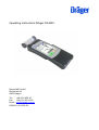
1
Operating Instructions Dräger FG4200
Dräger MSI GmbH
Rohrstraße 32
58093 Hagen
Tel.:
+49 2331 958 40
Fax:
+49 2331 95 84 29
Email: [email protected]
5695051; 2015-04-23
Operating Instructions Dräger FG4200
Table of Contents
1. Notes
Page 3
1.1 Certification
1.2 Usage
1.3 Maintenance
1.4 Disposal
Page 4
2. The measuring device
Page 5
3. First time use and general operation
Page 6
3.1 Preparation for first time use
3.1.2 Prior to each measurement
3.1.3 Touch screen
3.2 Switching on / off
3.2.1 After each measurement
3.3 Control panels
3.4 Customer and site management
3.5 Integrated operating instructions
3.6 Starting measurements
3.7 Displaying results
3.8 Documentation menu
Page 7
Page 8
Page 9
Page 10
4. Main menu
Page 11
5. Selecting and entering customer data
Page 11
6. Flue gas measurements
Page 12
6.1 Connecting the flue gas probe
6.2 Selecting fuels
6.3 Measuring combustion air temperature
6.4 Flue gas measurement
6.5 Average value measurement
6.6 Draft measurement
6.7 Entering combustion system data
6.8 List of display values
7. Pressure measurements
Page 12
Page 13
Page 14
Page 15
7.1 Connection diagram
7.2 Pressure measurement
8. Checklists
5695051
Page 15
1 of 26
2015-04-23
Operating Instructions Dräger FG4200
Table of Contents (page 2)
9. Data memory
Page 16
9.1 Saving measurements
9.2 Data memory functions
9.3 Data storage information
9.4 Display data
9.5 Inspector table
9.6 Deleting measuring data
Page 17
Page 18
10. Device information
Page 18
11. Settings
Page 19
11.1
11.2
11.3
11.4
11.5
11.6
11.7
11.8
11.9
11.10
11.11
11.12
11.13
Date and time
Key beep
MSI printer
Display backlight
Display integrated operating instructions
Automatic daylight saving time
Entering combustion system data
Draft measurement
Calorific value
Extended fuel table
30 s average
Printer footer texts
Language
Page 20
Page 21
12. Warnings and alarms
Page 22
13. Power supply
Page 23
13.1 General power supply information
13.2 Charging batteries
14. Technical specifications
Page 24
14.1 General technical specifications
14.2 Technical specifications flue gas and pressure measurements
15. Maintenance and care
Page 25
16. Consumables and accessories
Page 25
17. Managing PC measuring data
Page 25
2015-04-23
2 of 26
5695051
Operating Instructions Dräger FG4200
1. Information
1.1 Certification
The Dräger FG4200 flue gas measurement device is tested according to the requirements
of the European standard EN 50379 Parts 1 and 3.
1.2 Usage
The Dräger FG4200 flue gas measurement device is suitable for measuring combustion
parameters of heating systems. It is not suitable for use as a continuously operating gas
warning and alarm device.
Any use of this device requires full understanding and compliance with these operating
instructions, the relevant standards, as well as the relevant statutory regulations.
The device is intended only for the uses described in this manual. Any improper use of the
device may lead to electric shock or destruction of the measuring device!
Always fully charge the Dräger FG4200 via the USB interface with a 5 V DC / 1 A
USB power supply adapter only.
Incomplete charging affects the charging capacity of the battery in the long term.
When charging, no measurements should be performed.
The displays shown in this manual are examples.
Only recorded measurements can be printed or saved.
The device employs fuel-specific formulas to calculate CO2 and qA (flue gas loss) combustion parameters. For this reason, these combustion parameters can only be calculated
for the fuels which are saved in the fuel table of the device. The following fuels can be set:
Light fuel oil, natural gas, LPG propane, heavy fuel oil, pellets, wood, brown coal, hard
coal, coal briquettes, coal coke, anthracite, biogas, LPG butane, coal gas, coke oven gas.
The lifetime of the sensors used in the Dräger FG4200 is typically 4 years for both the O2
sensor and the CO sensor. The pressure sensor has no limited lifetime under normal-use
conditions.
To avoid influencing the measuring accuracy of the sensors, the Dräger FG4200 must not
be exposed to solvents, fuels or plasticizers during operation and storage.
5695051
3 of 26
2015-04-23
Operating Instructions Dräger FG4200
1.3 Maintenance
To ensure proper function and accuracy, calibration and adjustment should be performed
once a year. Device maintenance must only be carried out by trained service personal.
1.4 Disposal according to WEEE
Since 2005, EU-wide regulations apply to the disposal of electrical and electronic
devices. In essence, these regulations set out that collection and recycling
options should be available for households. Because the Dräger FG4200 is not
registered for use in private households, it must not be disposed of through such channels. The devices can be returned to your national retailer or to your national Dräger Safety Organization for disposal. Please contact Dräger MSI GmbH, if you have any questions
regarding disposal.
2015-04-23
4 of 26
5695051
Operating Instructions Dräger FG4200
2. The measuring device
The Dräger FG4200 is an all-purpose, electronic multi-channel device for calibration and
testing work on small and medium-sized combustion systems.
All tests and measurements can be documented through print outs or storage.
Gas preconditioner
USB interface
Backlit colour display with
touch screen
Charging light,
IR transmitter
Gas outlet
Probes / gas connections
Connections
USB interface
Charging light + IR transmitter
T connection for the temperature gauge of the flue gas probe
P connection for draft measurement
5695051
G connection for flue gas measurement
5 of 26
2015-04-23
Operating Instructions Dräger FG4200
3. First time use and general operation
3.1 Preparation for first time use
Before using the measuring device, the integrity of all components must be checked, e.g.:
−
−
−
−
−
Device exhibits no visible damage
No condensed water in the gas preconditioner
The gas preconditioner filter is clean
Gas hoses without defects
Visual inspection of the probe
Connect the quick-release hose coupling of the flue gas probe into the gas inlet G of the
measuring device and the jack plug of the flue gas probe in the temperature input T of the
measuring device. Ensure before each measurement that a clean filter is inserted in the
gas preconditioner!
Only turn the Dräger FG4200 on, if the flue gas probe is located in fresh air. The null signals of the sensors are matched with the fresh air.
3.1.2 Prior to each measurement
The air-tightness of the gas path can be tested easily: Close the gas inlet of the probe with
the round cap. If the gas path is not leaking, the pump should now deliver more power.
The sound of the pump changes accordingly. If no change occurs, then the gas path must
be checked with a gas flow meter.
3.1.3 Touch screen
The Dräger FG4200 is controlled by a touch-sensitive display (touch screen). You can execute typing and scrolling functions on the screen using your finger or a plastic pen. Ballpoint pens, pencils, metal pins, etc. are not suitable.
Because the display contains a resistive touch screen, slightly more pressure must be applied during operation compared with today’s smartphones with their capacitive touch
screens.
Menus and lists can be moved up and down by up/down swiping gestures (scrolling).
Menus and lists positions are highlighted by tapping. The selected item is activated via the
selection button or by tapping again.
Touching the display with sharp or pointed objects may lead to the destruction of
the display.
2015-04-23
6 of 26
5695051
Operating Instructions Dräger FG4200
3.2 Switching on / off
Switch on: Approx. Press the display lightly for 1 second, until the display is illuminated.
Battery icon
The home screen shows the device type, the software version, date and time and the device number. The battery icon displays the charge level of the battery.
The Next button switches to the main menu. If the button is not pressed within 5 seconds
after switching on, the device switches off automatically. Afterwards the Dräger FG4200
checks its functions with a system check. If scheduled maintenance is pending, the device
issues a reminder one month prior to the date of scheduled maintenance.
The Dräger FG4200 requires about 30 seconds from switching on until full readiness for
operation.
Switching off: Select and activate the OFF menu item in the main menu or press the display for 5 seconds whilst in any menu point.
3.2.1 After each measurement
After the measurement, remove the probe from the flue gas flow and let it suck up fresh
air for 1-2 minutes, then switch off the appliance. Empty and clean the gas preconditioner.
To open the gas preconditioner, remove the two plugs by hand. The filters and the filter
fleece must be checked for contamination and replaced if necessary.
Gas preconditioner
Plug | Condensate output | Filter fleece | Filter disk | Filter Cone | Plug
5695051
7 of 26
2015-04-23
Operating Instructions Dräger FG4200
3.3 Control panels
Menu
Select
OK
= opens the context menu for the selection and editing of system data
= enables the marked position
= confirms a selection
Finish
= leads to the next step of function after an action
Next
= leads to the next step of a function
Cancel
= ends a function, switches to the main menu
>>
= scrolls forwards, display switches to chart
<<
= scrolls backwards, display switches to statistical data
Null
= readjusts the zero point of the pressure sensor
Start
= starts the measurement
Stop
= stops the measurement
New
= prepares a new measurement
Docu
= switches to the documentation menu
Back
= switches to the results display from the documentation menu
Customer
= switches from the documentation menu to site selection
Print
= prints the measurement result of the IR transmitter
Save
= saves the measuring result in data memory
End
= switches from the documentation menu to the main menu
Input
= opens the input option for printer text
2015-04-23
8 of 26
5695051
Operating Instructions Dräger FG4200
3.4 Customer and site management
The Menu button opens a shortcut menu. Used together
with the menu item, the context menu provides
different processing options and commands.
Customer data and comments can be entered via an on-screen keyboard.
3.5 Integrated operating instructions
In the Settings menu item, integrated operating instructions can be
activated. When operating instructions are switched on,
the corresponding instructions are shown when starting a function.
Scroll between pages with >> and <<.
The measurement program is started with the Next button.
5695051
9 of 26
2015-04-23
Operating Instructions Dräger FG4200
3.6 Starting measurements
Before starting a measurement, the connection used for the measurement is indicated.
3.7 Displaying results
A result display appears after completing a measurement.
3.8 Documentation menu
After completing the measurement, the documentation menu can be
opened.
If no customer was selected prior to measurement, a
customer can be selected or created here.
The measurement result is assigned to the customer via Save.
If no customer is selected, the measurement result is just saved
with date and time.
Pressing Print allows the measurement result to be sent via the
integrated IR transmitter to an infrared printer.
2015-04-23
10 of 26
5695051
Operating Instructions Dräger FG4200
4. Main menu
Selectable menu items are:
OFF:
Customers / sites:
Flue gas measurement:
Pressure:
Checklists:
Data memory:
Info:
Settings:
Switch off the measuring device
Select and edit customer / site records
Flue gas analyses with selectable parameters
Basic pressure measurement
Select, edit and save checklists
Data memory information, stored measurements,
and inspector table
Device information
Change device and measurement settings, set clock
5. Selecting and entering customer data
Customers and site records can be created and edited. Completed
measurements can then be saved under the set-up customers and
sites. Via a link in the documentation menu, customers and sites can
be created after the measurement.
In addition, it is also possible to create customer and site records with
the software and to transfer data to the device.
Select:
Menu:
The displayed customer number is transferred.
The context menu is opened.
Without:
New:
Edit:
Search:
Delete:
Measurements are saved without site link.
New customer data can be created.
You can edit existing records.
You can search for a string.
You can delete the selected record. That is only
possible, if no measurement data is saved in
the device.
5695051
11 of 26
2015-04-23
Operating Instructions Dräger FG4200
The following can be stored: customer number, name, system type,
system place, site number, street, post code, city, customer name,
customer street, customer post code, customer city, customer phone
number, boiler manufacturer, boiler type and year of manufacture,
boiler output, burner manufacturer, burner type and year of manufacture, burner design and fuel.
The acquired customer number applies to all subsequent measurements until it is switched off or another number is selected.
6. Flue gas measurement
To perform a complete flue gas measurement, we recommend a measurement time of at
least 2 minutes.
The gas outlet at the side of the device must be free and must not closed or
clogged!
6.1 Connecting the flue gas probe
Turn the Dräger FG4200 on and press Next.
After the system check, the Dräger FG4200 is ready for use. Select
Flue gas measurement in the main menu.
Connect the flue gas probe to the device (see connection diagram).
Plug the jack plug of the flue gas probe in the temperature input T
and the quick-release coupling of the flue gas probe hose into the gas
input G of the measuring device. Then press Next.
6.2 Selecting fuels
Select the desired fuel and accept.
If the pump was shut off before selection of flue gas measurement
function, a short stabilization phase will be performed.
2015-04-23
12 of 26
5695051
Operating Instructions Dräger FG4200
6.3 Measuring combustion air temperature
The Dräger FG4200 will now ask you to measure the combustion air
temperature. Place the flue gas probe in the inspection opening of the
combustion air intake or alternatively hold the flue gas probe in the
room air.
As soon as the combustion air values have stabilized, press Hold. If
an oxygen content of less than 21% is measured in the combustion
air supply, this implies under circumstances a leak in the exhaust pipe
in the air-exhaust system.
6.4 Flue gas measurement
Within the exhaust stream, there are areas which only partially mixed
with exhaust. For this reason, it is necessary to take the sample from
the flow centre. The flow centre is characterized by maximum flue gas
temperature and minimum oxygen concentration.
Press the arrow button >>, once the combustion air measurement is
complete.
Now insert the flue gas probe into the exhaust pipe, move it in the
exhaust stream and position it so that the tip of the sensor is the flow
centre (maximum gas temperature, minimum oxygen concentration).
After you've found the flow centre and the measurement values have stabilized, fix the
flue gas probe in this optimal position with the sensor cone. A summary of currently
measured combustion values is then displayed. Then press the Hold button and then the
arrow button >>. By pressing the arrow button >> again, you can display the other measurement results.
6.5 Average value measurement
The German regulation 1st BImSchV calls for simultaneous determination of oxygen content and temperature of flue gas as an average
over a time period of 30 seconds. If average measurement is enabled in the settings, you can begin the 30-second averaging process
by pressing Start, no need to press Hold.
5695051
13 of 26
2015-04-23
Operating Instructions Dräger FG4200
6.6 Draft measurement
If draft measurement is enabled in the settings, the draft (differential
pressure) of the flue gas can be measured. This requires moving the
flue gas probe from gas inlet G to pressure connection P.
6.7 Entering combustion system data
If the input of combustion system date has been enabled in the device settings, the boiler temperature, the smoke numbers and the appearance of oil derivatives can be entered. It is only necessary to enter smoke numbers and oil derivatives in case of combustion with fuel
oils (light fuel oil and heavy fuel oil) and are only available for measurements with these fuels. Once the input data is complete, press the
arrow button >>.
The result summary is then displayed and can be scrolled through
using the arrow buttons << / >>.
6.8 List of display values
T-A
T-G
O2
CO
CO2
qA
CO-0
Eta
T-Dew
Lambda
Draft
T-boiler
O2-A
Smoke no.
Oil derivative
2015-04-23
Combustion air temperature
Flue gas temperature
Measured oxygen
Measured carbon monoxide
Measured carbon dioxide
Determined flue gas loss of flue gas
Determined carbon monoxide content relative to 0 vol. % oxygen
Determined combustion-technical combustion efficiency
Determined temperature of the dew point
Determined combustion air ratio
Measured induced draft
Entered boiler temperature
Measured oxygen content of combustion air
Average of the entered smoke numbers
Consideration of oil derivatives
14 of 26
5695051
Operating Instructions Dräger FG4200
7. Pressure measurements
7.1 Connection diagram
For pressure measurement up to 160 mbar (gas, nozzle or kinetic
pressure), connect the measuring point using the burner pressure
hose with the pressure input P of the measuring device.
7.2 Pressure measurement
Selectable functions are:
Zero:
the displayed value is set to zero
>> / <<:
Switching between statistics and chart
Start:
Start the pressure measurement
Cancel:
Cancellation of the pressure measurement
To begin press the Start button, according to desired duration with
Stop to stop the measurement.
After starting the pressure measurement, the current pressure, the
starting pressure, the difference between the starting pressure and
the previous measurement duration are displayed. The final pressure
is displayed, if the measurement is suspended. During the measurement, you can switch to the graph view with the arrow button >>.
After completing the pressure measurement, the result is displayed.
8. Checklists
Measurement specifications often include visual inspections and other controls that have
nothing to do with the actual measurement. Such additional information regarding the
measurements or the equipment can be recorded with checklists. Even work instructions
can be created and processed in this manner.
Up to 4 checklists with maximum 20 entries can be created using the PC data management. Each entry can be created so that it can be answered with Yes / No, or with a max.
5 characters long input. If no input has been provided, the entry is represented with ---.
5695051
15 of 26
2015-04-23
Operating Instructions Dräger FG4200
9. Data memory
9.1 Saving measurements
If no site number was selected prior to measurement, the measurement of a site can be assigned before saving, by pressing Customer
under the documentation menu.
Without site assignment, the measurement is saved with date and
time.
By assigning a site, the site number is displayed in addition.
9.2 Data memory functions
Selectable functions are:
Info:
Show data:
Inspectors table:
Delete measurements:
Delete all customers:
2015-04-23
Data storage information
Show stored record
Viewing and editing the Inspectors table
Delete measurement data storage
Delete all customer data
16 of 26
5695051
Operating Instructions Dräger FG4200
9.3 Data storage information
The number of stored customers and measurements, and the total
number of occupied memory locations, are displayed in the data storage information.
9.4 Show data
The measurement is saved with date and time and site number,
if a site has been assigned.
Select calls up the measurement results display.
With Docu the assigned site is displayed and the measurement
result can be printed out with site and inspector.
5695051
17 of 26
2015-04-23
Operating Instructions Dräger FG4200
9.5 Inspectors table
In the inspectors table different inspectors can be entered with number, name, street, postcode, town and phone number information.
The selected inspector is associated with the stored measurement
data. An inspector can only be deleted, if no measurement data is
saved in the device.
9.6 Deleting measuring data
Deleting measuring data: All measured data are deleted.
10. Device information
This function provides information about the manufacturer (Dräger),
the measuring device type (FG4200), the version of the device software (here 1.1,040), the device serial number, the set date, the set
time, the selected inspector and the next service date.
2015-04-23
18 of 26
5695051
Operating Instructions Dräger FG4200
11. Settings
The measuring device can be configured according to user's requirements.
The functions are switched on and off via the control panel or switched to the input.
Settings Page 1
Date and time:
Key beep:
MSI printer:
Display:
Show help:
Auto. dayl.-saving:
Date and time can be set.
The key beep can be switched on or off.
The MSI printer protocol can be switched
on or off.
The display lighting can be set.
Built-in help texts can be enabled or
disabled.
Automatic adjustment of daylight
saving time can be switched on or off.
The arrow button >> allows you to switch to the second settings page.
Settings Page 2
Enter system data:
Draft measurem.:
Calorific value:
Extend fuel table:
Average meas.:
Entering the combustion system data during
the flue gas measurement can be switched
on or off.
The draft measurement during the flue gas
measurement can be switched on or off .
Switch consideration of calorific value on
or off.
Display the extended fuels table.
Switch average measurement on or off.
Pressing the arrow button >> again allows you to switch to entry of a
foot text for the IR printer and language configuration.
5695051
19 of 26
2015-04-23
Operating Instructions Dräger FG4200
11.1 Date and time
Setting and changing date and time.
Enter the desired date and time with the numeric keypad. Switch to
the changed position with the arrow buttons << / >>.
Confirm the input with OK.
11.2 Key beep
This function allows you to turn the key beep on and off.
11.3 MSI printer
This function allows you to switch between the printer logs for MSI printer and HP printers.
MSI IR3 printers: The data transfer and printing rates are faster than HP protocol compatible printers.
HP printers: The data transfer rate corresponds to the HP protocol and is also suitable for
all HP protocol compatible printers, and of course for the MSI IR3.
11.4 Display backlight
This function allows you to set the display brightness to 50%, 75% or 100%. The display
brightness affects battery life.
11.5 Show integrated operating instructions
This function allows you to turn the integrated operating instructions on and off.
11.6 Automatic daylight saving
This function allows you to turn automatic daylight saving on and off.
11.7 Entering combustion system data
Entry of combustion system data during the flue gas measurement can be switched on or
off. This includes taking into account boiler temperature, smoke numbers and oil derivatives.
2015-04-23
20 of 26
5695051
Operating Instructions Dräger FG4200
11.8 Draft measurement
If draft measurement should be considered during flue gas measurement, this can be
switched on or off here.
11.9 Calorific value
Enabling takes account of negative qA and ETA values in the measurement. This function
should be always active for calorific value systems, so that measurement results are valid.
11.10 Extended fuel table
The fuel table, which includes light fuel oil, natural gas, LPG propane, heavy fuel oil and
pellets is extended by the following fuels:
wood, brown coal, hard coal, coal briquettes, coal coke, anthracite, biogas, LPG butane, coal gas, coke oven gas
11.11 Average
The 30-second average value measurement according to the German regulation BImSchV during the flue gas measurement can be switched on or off.
11.12 Printer footer texts
With this feature, the printer footer text for the infrared printer can be changed line by line.
Pressing OK after entry changes to the next line.
11.13 Language
A country-specific language configuration can be set with this function.
5695051
21 of 26
2015-04-23
Operating Instructions Dräger FG4200
12. Warnings and alarms
In the starting phase and during measurement, the measurement device checks proper function. Warnings and alarms are displayed after
the start-up phase or during the normal operation.
Possible displays:
Next service
If a scheduled service is pending, the device issues a reminder one month prior to the
date of scheduled maintenance.
Clock not set
Date and time must be set, e.g. after deep-discharging of the battery.
Charge control
The battery must be charged.
Settings
Check settings and change if necessary.
Printer text
An error has occurred in the printer text. Reenter printer text or transfer from the PC.
Data memory
Confirm the question “Reinitialize memory?” This will erase the data memory.
Calibration
An error has occurred in the calibration data. Return device for servicing.
Options
An error has occurred in the options data. Return device for servicing.
Fuel table
An error has occurred in the fuel table. Return device for servicing.
Bluetooth
An error has occurred in the Bluetooth configuration. Return device for servicing.
Pump adjustment
An error has occurred in the pump adjustment. Return device for servicing.
2015-04-23
22 of 26
5695051
Operating Instructions Dräger FG4200
13. Power supply
13.1 General power supply information
A rechargeable lithium ion battery built into the device provides mains-independent operation. The operating time with fully charged battery is up to 8 hours, this can vary depending on the type of measurements and the display brightness set.
13.2 Charging batteries
The charge state of the battery is monitored by the meter and shown in the display. The
battery symbol on the display indicates the charge state. The red charging light on the device side flashes in event of a discharged battery. The device should now be charged. Always charge the measuring device fully with a 5 V DC / 1 A USB power supply adapter
only. For longer periods of inactivity, we recommend a monthly charge. The USB power
adapter supplied with the device is designed to operate at 100 - 240 V AC. For safety reasons, the condition of the power supply should be checked regularly for damage.
The charging process takes 1 - 4 hours, depending on the charge state. During charging,
the red LED on the side of the device flashes. The flashing ceases and the LED lights
continuously after the charging process is complete. This means that the battery is full and
is now powered with a trickle charge current.
If battery charging fails, the device switches off automatically. If the device can no longer
be turned on due to low voltage, the USB power adapter must be connected and the device switched on again!
Total discharge of the battery should be avoided, as this may shorten the life of the battery.
5695051
23 of 26
2015-04-23
Operating Instructions Dräger FG4200
14. Technical data
14.1 General technical specifications
Display:
Interfaces:
Power supply:
Colour display with touch screen
USB, IR
Li-ion battery, 3.6 V, 1500 mAh, charge level indicator
Primary charger 100 - 240 V AC; Secondary 5 V DC, 1 A
Battery life:
Typical 8 hours
Dimensions:
75 x 200 x 27 mm (W x H x D)
Weight:
approx. 258 g
Operating temperature: + 5 °C to + 40 °C
Storage temperature: - 20 °C to + 50 °C
Relative humidity:
10 - 90 % RH, not condensing
Air pressure:
800 to 1100 hPa
Certification:
DIN EN 50379 Part 1 and Part 3
14.2 Technical specifications for flue gas measurement and pressure measurements
Display
Combustion air temperature
Principle of
measurement
Measuring range
Resolution
Accuracy
Thermocouple
- 10 … + 100°C
0.1 °C
< ± 1 °C
0 … + 600 °C
0.1 °C (< 100 °C) < ± 2 °C or
1 °C (≥ 100 °C)
< ± 1.5 % of MV*
Flue gas temperature Thermocouple
O2, oxygen
El.-chem. sensor
0 … 25 vol %
0.1 vol %
CO, carbon monoxide
El.-chem. sensor
0 … 8,000 ppm
1 ppm
Draft**
Piezo bridge
- 50 … + 200 Pa
1 Pa
0 … 100 mbar
0.01 mbar
Pressure**
Piezo bridge
+ 100 … 160 mbar
*MV = Measurement value ** = Pmax. 750 mbar
0.1 mbar
< ± 0.3 Vol %
0 … 4,000 ppm:
< ± 20 ppm or
or < ± 5 % of MV*
< ± 2 Pa or
or < ± 5 % of MV*
0.5 mbar or
< ± 1 % of MV*
or < ± 5 % of MV*
Calculated values
CO, undiluted
calculated
0 … 9,999 ppm
1 ppm
CO2, carbon dioxide
calculated
0 … CO2 max.
0.1 vol %
Flue gas losses
calculated
0 … + 100 %
- 20 … + 100 %***
0.1 %
Efficiency
calculated
0 … + 100 %
0 … + 120 %***
0.1 %
Excess air
calculated
1.00 ... 9.99
0.01
CO/CO2 ratio
calculated
0 … 0.01
0.0001
*** = taking into account of the gain in calorific value
2015-04-23
24 of 26
5695051
Operating Instructions Dräger FG4200
15. Maintenance and care
The measuring device should be checked once a year by an authorized service partner to
preserve accuracy and safe function and be adjusted, if necessary.
The device can be cleaned with a damp, not wet, cloth. Do not use any chemical cleaning
agents. Make sure that the device connections are not blocked or dirty.
16. Consumables and accessories
5600907
Consumables set incl. 10 filter fleece and 5 filter discs
5600401
IR3 printer with infrared data transmission
5690151
Printing paper for printer
5680124
USB power adapter 100 – 240 VAC
5650831
USB cable, 1 m
5600890
Flue gas probe FG4x00
5610709
Burner pressure hose P4000
5600906
Device bag FG4x00
5610733
Magnetic rubber set
17. Managing PC measuring data
To download the measurement data management go to our website http://www.draegermsi.de/home/?L=1 under the menu item Online-Services → Download → FG4200. The
necessary USB drivers are installed automatically.
5695051
25 of 26
2015-04-23