1
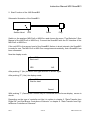
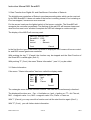
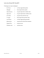
Instruction Manual MSI Smart-BCI
Dräger Safety MSI GmbH
Rohrstraße 32
D - 58093 Hagen
Tel.:
049-2331 / 9584 - 0
Fax:
049-2331 / 9584 - 29
e-mail: [email protected]
D 910; Edition 2005-07-20
Instruction Manual MSI SmartBCI
Contents
1. Hints and General Function
1.1
Hints
1.2
General Function
Page 2
2. Start Function of the MSI SmartBCI
Page 3
3. Data Transfer from Digital Oil- and Gas-Burner Controllers of Satronic
Page 4
3.1
Status Information
3.2
Error Statistics
Page 5
4. Data Transfer from Digital Burner Controllers of Siemens
4.1
4.2
Page 7
Siemens Oil Burner Controllers
4.1.1 Status Information
4.1.2 Data Transfer Error
Page 8
Page 9
Siemens Gas Burner Controllers
Page 10
4.2.1 Status Information
Page 11
5. Printing
6. Data Transfer Error
D910
Page 12
1 of 12
Edition 2005-07-20
Instruction Manual MSI SmartBCI
1. Hints and General Function
1. 1 Hints
Any use of a MSI 150 with MSI SmartBCI, requires a full understanding and strict adherence to the instructions of this manual and the manuals of the Burner (Controller) and the
used MSI 150.
The MSI-Pro2 or MSI-EURO with MSI SmartBCI are able to read out the digital burner
controllers of Siemens (Landis & Staefa) and Satronic.
The data, which are given by the digital burner controllers, differ depending of the manufacturer and of the fuel type. Therefore the description of the data transfer in this manual is
separated for each type of burner controller.
The MSI Smart BC recognizes the type of the different digital burner controller itself and
the MSI 150 Pro2 or the MSI 150 Euro will carry out automatically all adjustments which
are needed for the data transfer between MSI SmartBCI and MSI 150 Pro2 or MSI 150
Euro.
Because the MSI Euro possesses a display with only 4 it will differ slightly from the display
screens of the MSI Pro2 which are shown in this manual.
All shown displayed data are only examples.
1.2 General Function
The SmartBCI is a processor controlled device, designed to read out digital burner
controllers of Siemens (Landis & Staefa) and Satronic. The power supply is done by the
MSI 150 Pro2 or the MSI 150 Euro.
The SmartBCI contents 2 sensors, one for visible light and the other for infra red light,
which receive the signals emitted by the digital burner controllers. The signals will be decoded, formatted and stored by the microprocessor integrated in the SmartBCI.
The principles of the operations of the SmartBCI are registered at the German patent office by patent Nr. 10313079 "Auslesevorrichtung für Brennersteuerungen".
Analyzer and SmartBCI interact and transfer the data from the SmartBCI to the MSI-Pro2
or MSI-Euro. The analyzer displays the data as text in clear.
Edition 2005-07-20
2 of 12
D910
Instruction Manual MSI SmartBCI
2. Start Function of the MSI SmartBCI
Schematic Illustration of the SmartBCI:
Sensor Head
LED
Cable
Plug
Switch on the analyzer MSI-Pro2 or MSI-Euro and choose the menu "Fuel Selection" (See
Manual of the MSI-Pro2 or MSI-Euro). Connect the SmartBCI with the PC interface of the
MSI-Pro2 or MSI-Euro.
If the red LED in the sensor head of the SmartBCI flashes in short intervals, the SmartBCI
is ready for use. The MSI-Pro2 or MSI-Euro recognizes automatically, that a SmartBCI has
been connected.
Now the display reads:
Smart BCI
Start now?
YES
NO
After pushing "!" (No) the menu fuel type selection is shown again.
After pushing "F" (Yes) the display reads:
Smart BCI
Wait for data!
Cancel
With pushing "!" (Cancel) the function may be cancelled and the former display screen is
shown.
Depending on the type of controller act like it is written in chapter 3. "Data Transfer from
Digital Oil- and Gas-Burner Controllers of Satronic" or chapter 4. "Data Transfer from Digital Burner Controllers of Siemens".
D910
3 of 12
Edition 2005-07-20
Instruction Manual MSI SmartBCI
3. Data Transfer from Digital Oil- and Gas-Burner Controllers of Satronic
The digital burner controllers of Satronic are always sending data, which can be received
by the MSI SmartBCI. It does not matter if the burner is working normal, if he is starting or
if he has stopped, because an error occurred.
Put the sensor head over the lighted switch of the burner controller. The SmartBCI will
recognize the controller immediately.The flashing of the red LED will become slower and
when the first read out of all data is complete the LED will change to continuous light.
The display of the MSI-Pro2 now may read:
DKO 976 Mod.05 230V
SmartBCI 1.1,005
State
: OK
control.
: Satronic
Cont.
Cancel
In the first line the type of the burner controller is displayed. DKO means oil burner controller and DKG means gas burner controller.
With pushing the key "!" (Cancel) the function may be stopped and the Start Function of
the Smart BCI is called again (See 2.).
With pushing "F" (Cont.) the menu "Status Information" (see 3.1) my be called.
3.1 Status Information
If the menu "Status Information" has been called the display reads:
DKO
Fan.
MV1
MV2
976 MOD.05 230 V
█
Ignit.
█
FT
█
█
Flame
█
Cont.
Cancel
The rectangles mean that the function is active. The data will be continuously refreshed .
The displayed functions are: Fan. = Ventilation on, Ignit. = Ignition on, FT = Air Flow ok,
MV1 = magnetic valve 1 on, MV2 = magnetic valve 2 on, Flame = Flame on
With "!" (Cancel) you may cancel the function and call the start function again (See 2.).
With "F" (Cont.) you call further status information.
Edition 2005-07-20
4 of 12
D910
Instruction Manual MSI SmartBCI
After pushing "F" (Cont) the display shows:
Fl. intensit
Voltage
Rest TS
2,3 uA
231 V
3,0 s
Cont.
Cancel
If an error occurs you see, instead of the measured values, bars.
With pushing "!" (Cancel) the function may be cancelled and the start function of the
SmartBCI is called (See 2.).
With " F " (Cont.) you change to error statistics (see 3.2).
3.2 Error Statistics
If you have chosen error statistics the display reads:
Starts total
Error statistics
Last error
Airpc stays op.
Prior error
No Flame
348
With "▲" you may scroll the displayed values and new elements will be shown.
The display then reads for instance:
Errors total
Stray light
Safety time
Loss flame
Starts/reset
Starts/fault
48
17
9
15
120
1
With "!" you may cancel the function and call the start function again (See 2.).
By pushing the button "F" you may call the menu "Printing" (see 5.).
D910
5 of 12
Edition 2005-07-20
Instruction Manual MSI SmartBCI
Following errors may be displayed:
No Flame
=
no flame signal after ignition
Straylight
=
flame signal before ignition
Airpc stays op.
=
air guard open after ventilator start
Airpc open
=
air guard open before ventilator start
AF closed
=
air guard close after fan stop
Fl. signal
=
flame signal after operation stop
Loss Flame
=
no flame signal during operation
Manual stop
=
manual reset of the burner controller
System Error
=
electronic error
Unknown error
=
unknown error
Edition 2005-07-20
6 of 12
D910
Instruction Manual MSI SmartBCI
4. Data Transfer from Digital Burner Controllers of Siemens
4.1 Siemens Oil Burner Controller
Before data can be transferred, the burner controller has to be set to interface diagnosis
mode (see user manual burner / burner controller).
If the burner is shut off (the light in the burner controller switch is off) you may set the
burner controller to interface diagnosis mode by pressing the burner controller button for
more than 3 seconds. The red light in the switch is now flickering.
Shows the burner controller an error (the light in the burner controller is red), you may set
the burner controller to visual diagnosis mode by pressing the burner controller button for
more than 3 seconds. The red light in the switch is now blinking red. Now press the button
for more than 3 seconds again. This will set the burner controller into interface diagnosis
mode, the red light in the switch is now flickering.
Put the sensor head over the lighted switch of the burner controller. The SmartBCI will
recognize the controller, the flashing of the red LED will become slower and the display
reads:
State
1
SmartBCI 1.1,005
State :
Waiting
control.
L&S
Cancel
With pushing the key "!" (Cancel) the " Start Function" of the Smart BCI" is called (See 2.).
When the first read out of all data is complete the LED will change to continuous light and
the display reads:
LMO84.110A2B
SmartBCI 1.1,005
State :
OK
control.
L&S
Cont.
Cancel
In the first line the type of the burner controller is displayed.
With "!" (Cancel) you may stop this function and the Start Function is called again (See 2.).
With "F" (Cont.) you call the menu "Status Information" (see 4.1.1).
D910
7 of 12
Edition 2005-07-20
Instruction Manual MSI SmartBCI
4.1.1 Status Information
If the menu "Status Information" has been called the display reads:
Thermo █
Fan.
█
MV1
█
MV2
█
Ignit.
Flame
Cont.
█
Cancel
The rectangles mean that the function is active. The data will be continuously refreshed .
The displayed functions may be:
Thermo
=
startfunction on
Fan.
=
ventilation on
Ignit.
=
ignition on
MV1
=
magnetic valve 1 on
MV2
=
valve 2 on
Flame
=
flame on
With "!" (Cancel) you may cancel the function and call the start function again (See 2.).
With "F" (Cont.) you may call further status information.
The display then reads:
Photo cur.
Voltage
1 uA
223 V
Cont.
Cancel
The displayed measuring value Fotocurr. means the current of the photo sensor.
With "!" (Cancel) you may cancel the function and call the start function again (See 2.).
With " F " (Cont.) you change to error statistics (see 4.1.2).
Edition 2005-07-20
8 of 12
D910
Instruction Manual MSI SmartBCI
4.1.2 Error Statistics
If you have chosen error statistics the display reads:
Current error
No flame
Start counter
81
Error history
-------------------------------------------Stray light
76
With pushing the button "F" you may call the menu "Printing" (see 5.).
With "▲" you may scroll the displayed values and new elements will be shown.
Following errors may be displayed:
D910
No flame
=
no flame signal after ignition
Fault air press
=
fault air pressure
Stray light
=
flame signal before ignition
CPI open
=
CPI open
Fault Servo
=
fault servo
Loss flame
=
no flame signal during operation
Timeout Heater
=
oil heater timeout error
Unkn. error
=
unknown error
9 of 12
Edition 2005-07-20
Instruction Manual MSI SmartBCI
4.2 Siemens Gas Burner Controller
Before data can be transferred, the burner controller has to be set to interface diagnosis
mode (see user manual burner / burner controller).
Shows the burner controller an error (the light in the burner controller is red), you may set
the burner controller to visual diagnosis mode by pressing the burner controller button for
more than 3 seconds.
Put the sensor head over the lighted switch of the burner controller. The SmartBCI will
recognize the controller immediately, the flashing of the red LED will become slower and
the display reads:
State
1
SmartBCI 1.1,005
State :
Waiting
control.
L&S
Cancel
With pushing the key "!" (Cancel) the function may be stopped and the Start Function of
the Smart BCI is called again (See 2.).
When the first read out of all data is complete the LED will change to continuous light
The display then reads:
LMG 21.230
SmartBCI 1.1,005
State :
OK
control.
L&S
Cont.
Cancel
In the first line the type of the burner controller is displayed.
With "!" (Cancel) you may stop this function and the Start Function is called again (See 2.).
After pushing "F" (Cont.) the "Status Information" is called (see 4.2.1)
Edition 2005-07-20
10 of 12
D910
Instruction Manual MSI SmartBCI
4.2.1 Status Information
If the "Status Information" has been called the display reads:
LMG 21.230
Start counter
Current error
Loss flame
429
Cont.
Cancel
In the 4. line the actual error is displayed. Following errors may be displayed:
[1] Straylight, [2] No flame, [3] Loss flame, [4] 4 * No flame, [5] LP not closed (air guard),
[6] LP opened , [7] Starting inhibit, [8] No diagnostic, [9] old software and General error.
By pushing the button "F" (Cont.) you call the menu "Printing" (see 5.).
5. Printing
If the menu "Printing" has been called the display reads:
Print
NO
YES
With pushing "!" (YES) the print out may be started.
With "F" (NO) you may skip back to the menu "Status Information"
During the printing the display will read:
printing…
Cancel
During the beginning of the printout you may stop printing by pushing "▲" (Cancel).
If the print out is finished or cancelled the function "Status Information" is shown.
D910
11 of 12
Edition 2005-07-20
Instruction Manual MSI SmartBCI
6. Data Transfer Error
If the connection between burner controller and MSI SmartBCI is disturbed, the display will
read:
State
1
SmartBCI 1.1,005
State :
No data
control.
Cancel
If the connection may be repaired (new mounting of the sensor head for example) the data
transfer is repeated is automatically.
By pushing the key "!" (Cancel) the function is cancelled and the "Start Function of the
Smart BCI" is called again (see 2.).
If the connection between SmartBCI and MSI 150 is disturbed the display will read
Data tranfer error
Cancel
With "!" (Cancel) you may call the "Start Function of the Smart BCI" (see 2.)
After a short while the display reads:
State
1
SmartBCI 1.1,005
State :
wait for data
control.
Cancel
After a few seconds, the data transfer is cancelled automatically and the "Fuel Selection
Menu" is shown (see instruction manual of the Pro2 or Euro).
Edition 2005-07-20
12 of 12
D910