1
8.1.2Handling
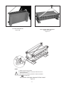
E.Where floor anchoring is required, position module/base
assembly in desired location. Mark floor through I-beam
holes and remove module/base assembly. Install floor
anchoring and reposition module/base assembly over
anchoring. Prior to installing nuts and washers, check that
assembly is level in both axes. Level using shims provided. Torque anchor hardware to manufacturer’s recommended value.
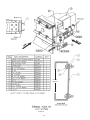
The module/base support assembly may now be removed
from the pallet using methods outlined in section 6.5,
Handling. Also see Figure 11. Remaining modules may be
removed in a similar manner.
8.1.3
Horizontal Stacking
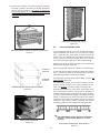
In order to stack modules in the horizontal position, refer to
Figures 11 thru 13 to perform the tip-over procedure. The
module/base support assembly tip-over should be performed
first. This procedure can be performed using a portable boom
crane or fork lift in conjunction with the lifting straps and lifting
shackles supplied.
CAUTION!
DO NOT ATTEMPT TO PERFORM TIP-OVER OF
MODULE MANUALLY AS SERIOUS PERSONAL
INJURY AND MODULE DAMAGE MAY RESULT.
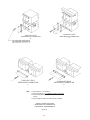
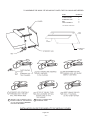
A. Install lifting strap using lifting shackles in channel base
holes at each end of module upper rear channel as
shown in Figure 12A.
B.
Center the lifting hook onto strap and lift until strap is
under tension and raises bottom of module from floor
surface so that upper and lower diagonal corners are in a
vertical mode.
C. While exerting manual force on the upper rear of module,
lower hoist until module is in horizontal position.
See Figures 12B and 13.
NOTE:
1) One strap with shackles used for tip-over
procedure.
2) Observe channel hole used as well as direction of
shackle insertion.
3) Tip over procedure for single modules only.
!
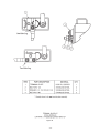
D. When module is horizontal, install the four lifting shackles
and two lifting straps as shown in Figure 14.
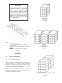
TIP OVER PROCEDURE
SHACKLE-STRAP USAGE
Figure 12A
F. U
sing Steps A-D and the layout/wiring diagram, position
the next module on top of first so that channels of each
mate with one another using drift pins to align channel
holes. Make sure channel ends and sides of the upper
and lower modules are flush. Install serrated flange bolts
and nuts in open holes, finger tight. Remove lifting straps.
Use leveling shims to fill gaps between trays. See Figures
15, 16, and 17A.
G.
HANDLING MODULE - BASE SUPPORT ASSEMBLY
Figure 11
-8-
At this time, check to see that the first two modules are
plumb front to back and side to side using wooden or
plastic level together with plywood straight edge. This is
to insure proper alignment for module interconnection
later on. Torque hardware to 47 Newton-meters
(35 Ft-Lbs).