1
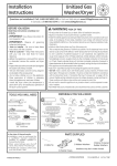
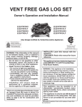
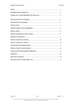
VENT FREE GAS LOG SET Owner’s Operation and Installation Manual RIVERSIDE OAK VENT FREE LOG SET RS18MVTNG RS18MVTLP RS24MVTNG RS24MVTLP and OVT22NG OVT22LP WARNING: If the information in this manual is not followed exactly, a e or explosion may result causing property damage, personal injury, or loss of life. — Do not store or use gasoline or other ble vapors and liquids in the vicinity of this or any other appliance. — WHAT TO DO IF YOU SMELL GAS Do not try to light any appliance. Do not touch any electrical switch; do not use any phone in your building. Immediately call your gas supplier from a neighbor’s phone. Follow the gas supplier’s instructions. If you cannot reach your gas supplier, rtment. — Installation and service must be performed by a qualified installer, service agency, or the gas supplier. This is an unvented heater. It uses air (oxygen) from the room in which it is installed. Provisions for adequate combustion and ventilation air must be provided. Refer to page 4, Air for Combustion and Ventilation. INSTALLER: Leave this manual with the appliance. CONSUMER: Retain this manual for future reference. This appliance has been tested and approved under ANSI Z21.11.2–2011 Unvented GasFired Room Heaters. WARNING: This appliance is for installation only in a solid fuel burning masonry or UL127 factory-built fireplace or listed ventless firebox enclosure. It has been design certified for these installations. EXCEPTION: DO NOT install this appliance in a factory-built fireplace that includes instruction stating it has not been tested or should not be used with unvented gas logs. This appliance may be installed in an aftermarket,* permanently located, manufactured (mobile) home, where not prohibited by local codes. This appliance is only for use with the type of gas indicated on the rating plate. This appliance is not convertible for use with other gases. * Aftermarket: Completion of sale, not for purpose of resale, from the manufacturer TABLE OF CONTENTS Safety Information ........................................................ 2 Local Codes ..................................................................3 Unpacking ..................................................................... 4 Product Features............................................................ 4 .............................................................. 4 ....................................... 4 ............................ 4 Installation..................................................................... 7 Operating Log Set .......................................................14 Inspecting Burners ...................................................... 16 Cleaning and Maintenance ..........................................17 .......................................................... 18 Parts List and Illustrated Parts Breakdown ................. 22 Warranty Information .................................. Back Cover SAFETY INFORMATION DANGER: ay lead to death! oxide Monoxide P : Early signs of monoxide poisoning dizand/or nausea. If you may not working properly. Get air at once! Have heater Some people–pregnant persons or lung under ence of at altitudes–are more affected Propane/LP Ga : Propane/LP gas is odorless. odormaking agent is added to gas. odor you detect a gas leak. odor added to gas can fade. Make certain you read and understand all warnings. Keep manual for reference. It is your guide to safe and proper WARNING: Any change to thi heater or it control can e dangerou . WARNING: Do not a lower heat exchanger rt, or other not approved f Y rt, ry e. liance. r air into the fireplace WARNING: roper , , alteration, rvice, or can ry or property age. Refer to nual for correct and operational pr . For or additional inf a r, rvice agency, or the plier. WARNING: g c California to or other repr 2 product and/or own to the of cancer or rth def WARNING: Do not allow to low directly into the appliance. Avoid any draft that alter urner . Ceiling can create that alter urner . Altered urner can Due to high , the appliance located out of and away fr Do not place clothing or other on or near the appliance. Never Fireplace front and very hot when running appliance. Keep children and away hot to avoid or clothing ignition. will hot for a after Allow Carefully young children when SAFETY INFORMATION CONTINUED Keep the appliance area clear and free from combustible materials, gasoline, and other 1. This appliance is only for use with the type of gas indicated on the rating plate. This appliance is not convertible for use with other gases. 2. Do not place propane/LP supply tank(s) inside any structure. Locate propane/LP supply tank(s) outdoors (propane/LP units only). 3. If you smell gas shut off gas supply do not try to light any appliance do not touch any electrical switch; do not use any phone in your building immediately call your gas supplier from a neighbor’s phone. Follow the gas supplier’s instructions if you cannot reach your gas supplier, call the department 4. This appliance shall not be installed in a bedroom or bathroom. 5. Do not use this appliance as a wood-burning Use only the logs provided with the appliance. 6. Do not add extra logs or ornaments such as pine cones, vermiculite or rock wool. Using these added items can cause sooting and poor combustion. Do not add lava rock around base. Rock and debris could fall into the control area of heater. 7. This appliance is designed to be smokeless. If logs ever appear to smoke, turn off appliance and call a qual d service person. Note: During initial operation, slight smoking could occur due to log curing and burning manufacturing residues. 8. To prevent the creation of soot, follow the instructions in Cleaning and Maintenance section. Keep the appliance area clear and free from combustible materials, gasoline and other ble vapors and liquids. 9. Before using furniture polish, wax, carpet cleaner, or similar products, turn heater off. If heated, the vapors from these products may create a white powder residue within burner box or on adjacent walls or furniture. 10. This appliance needs fresh air ventilation to run properly. This appliance has an Oxygen Depletion Sensing (ODS) safety shutoff system. The ODS shuts down the if not enough fresh air is available. See Air for Combustion and Ventilation, pages 4 through 6. If appliance keeps shutting off, see Troubleshooting, pages 17 through 20. 11. Do not run appliance where flammable liquids or vapors are used or stored under dusty conditions 12. Do not use this appliance to cook food or burn paper or other objects. 13. Never place any objects in the heater or on logs. 14. Do not use appliance if any part has been exposed to or under water. Immediately call a service technician to inspect the appliance and to replace any part of the control system and any gas control which has been under water. 15. Turn appliance off and let cool before servicing. Only a service person should service and repair appliance. 16. Operating appliance above elevations of 4,500 feet could cause pilot outage. 17. To prevent performance problems, do not use propane/ LP fuel tanks of less than 100 lbs. capacity. 18. Provide adequate clearances around air openings. LOCAL CODES Install and use appliance with care. Follow all local codes. In the absence of local codes, use the latest edition of The National Fuel Gas Code ANSI Z223.1/NFPA 54*. *Available from: American National Standards Institute, Inc. 1430 Broadway New York, NY 10018 National Fire Protection Association, Inc. Batterymarch Park Quincy, MA 02269 State of Massachusetts: The installation must be made by a licensed plumber or gas in the Commonwealth of Massachusetts. Sellers of unvented propane or natural red supplemental room heaters shall provide to each purchaser a copy of 527 CMR 30 upon sale of the unit. Vent-free gas products are prohibited for bedroom and bathroom installation in the Commonwealth of Massachusetts. 3 UNPACKING 1. Remove the carton and log wrap. 2. Remove all protective packaging applied to heater for shipment. 3. Make sure your logset includes one hardware packet. 4. Check heater for any shipping damage. If h eater is damaged, call SHM International at (800) 229-5647 for replacement parts before returning to dealer. PRODUCT FEATURES SAFETY PILOT This heater has a pilot with an Oxygen Depletion Sensing (ODS) safety shutoff system. The ODS/pilot is a required feature for vent-free room heaters. The ODS/pilot shuts off the heater if there is not enough fresh air. PIEZO IGNITION SYSTEM This heater has a piezo ignitor. This system requires no matches, batteries or other sources to light heater. THERMOSTATIC HEAT CONTROL Thermostat-controlled models have a thermostat sensing bulb and a control valve. The thermostat will automatically modulate the heat output to maintain a consistent room temperature. This results in greater heater comfort. This can also result in lower gas bills. SPECICICATIONS (BURNERS) MODEL (S,B)VFT18NG (S,B)VFT(22/24)NG GAS TYPE INPUT MAX INPUT MIN MANIFOLD INLET MIN INLET MAX NATURAL 34,000 BTUH 22,000 BTUH 3.5” W.C. 7” W.C 10.5” W.C. NATURAL 34,000 BTUH 22,000 BTUH 3.5” W.C. 7” W.C 10.5” W.C. MODEL (S,B)VFT18LP (S,B)VFT(22/24)LP GAS TYPE INPUT MAX INPUT MIN MANIFOLD INLET MIN INLET MAX LP GAS 34,000 BTUH 22,000 BTUH 10” W.C. 11” W.C 14” W.C. LP GAS 34,000 BTUH 22,000 BTUH 10” W.C. 11” W.C 14” W.C. 4 QUALIFIED INSTALLATION AGENCY Installation and replacement of gas piping, gas utilization equipment or accessories and repair and servicing of equipment shall be performed only by a agency. The term agency” means any individual, corporation, or company that either in person or through a representative is engaged in and is responsible for: A. Installation, testing or replacements of gas piping or B. Connection, installation, testing, repair or servicing of equipment that is experienced in such work; that is familiar with all precautions required; and that has complied with all requirement of the authority having jurisdiction. AIR FOR COMBUSTION AND VENTILATION WARNING: This heater shall not be installed in a room or space unless the required volume of indoor combustion air is provided by the method described in the National Fuel Gas Code, ANSI Z223.1/ NFPA 54, the International Fuel Gas Code, or applicable local codes. Read the following instructions to insure proper fresh air for this and other fuelburning appliances in your home. Today’s homes are built more energy efficient than ever.New materials, increased insulation, and new construction methods help reduce heat loss in homes. Home owners weather strip and caulk around windows and doors to keep the cold air out and the warm air in. During heating months, home owners want their homes as airtight as possible. While it is good to make your home energy your home needs to breathe. Fresh air must enter your home. All fuel-burning appliances need fresh air for proper combustion and ventilation. Exhaust fans, replaces, clothes dryers, and fuel burning appliances draw air from the house to operate. You must provide adequate fresh air for these appliances. This will insure proper venting of vented fuel-burning appliances. PROVIDING ADEQUATE VENTILATION The following are excerpts from National Fuel Gas Code ANSI Z223.1/NFPA 54,Section 5.3, Air for Combustion and Ventilation. All spaces in homes fall into one of the following 1. Unusually Tight Construction 2. VENTILATION AIR Ventilation Air From Inside Building The information on pages 5 through 6 will help you classify your space and provide adequate ventilation. Unusually Tight Construction 12" Ventilation Grills Into Adjoining Room, Option 1 The air that leaks around doors and windows may provide enough fresh air for combustion and ventilation. However, in buildings of unusually tight construction, you must provide additional fresh air. Unusually tight construction is as construction where: a. walls and ceilings exposed to the outside atmosphere have a continuous water vapor retarder with a rating of one perm (6 x 10-11 kg per pa-sec-m2) or less with openings gasketed or sealed and b. weather stripping has been added on openable windows and doors and c. caulking or sealants are applied to areas such as joints around window and door frames, between sole plates and rs, between wallceiling joints, between wall panels, at penetra tions for plumbing, electrical, and gas lines, and at other openings. If your home meets all of the three criteria above, you must provide additional fresh air. See Ventilation Air From Outdoors, page 5. Ventilation Grills Into Adjoining Room, Option 2 12" Figure 1 - Ventilation Air from Inside Building Ventilation Air From Outdoors Provide extra fresh air by using ventilation grills or ducts. You must provide two permanent openings: one within 12" of the ceiling and one within 12" of the Connect these items directly to the outdoors or spaces open to the outdoors. These spaces include attics and crawl spaces. Follow the National Fuel Gas Code ANSI Z223.1/NFPA 54, Section 5.3, Air for Combustion and Ventilation for required size of ventilation grills or ducts. IMPORTANT: Do not provide openings for inlet or outlet air into attic if attic has a thermostat-controlled power vent. Heated air entering the attic will activate the power vent. If your home does not meet all of the three criteria above, proceed to Determining Fresh-Air Flow for Appliance Location , page 6. Outlet Air Outlet Air Ventilated Attic To Attic To Crawl Space Inlet Air Inlet Air Ventilated Crawl Space Figure 2 - Ventilation Air from Outdoors 5 AIR FOR COMBUSTION AND VENTILATION Com are the maximum Btu/Hr the can ort with ____ CONTINUED ____ DETERMINING FRESH-AIR FLOW FOR APPLIANCE LOCATION Btu/Hr (maximum the Determining if You Ha Includes the room in which you will install any adjoining rooms with doorless Determine the volume of the - (length x width x Rework work sheet adding the s ace of an adjoining room If the extra an remove door to adjoining room or add ventilation grills between Ventilation Air from Inside Building Vent room directly to the from Outdoor Length x Width x Height = size 22 (length) x 18 (width) x If additional ventilation to adjoining room is with grills or add the volume of these rooms Install a lower Btu/Hr See Ventilation Air if lower Btu/Hr size If the actual Btu/Hr used is less than the maximum Btu/Hr the can the is an Multi ly the s ace volume by 20 to determine the maxi_______ (volume of s ace) x 20 = (Maximum Btu/Hr the s ace can s ) (maximum Btu/Hr t ft (volume of s ace) x 20 = can s ort) Add the Btu/Hr of all fuel burning Vent-free log set _______________ Gas water heater* ______________ Gas furnace___________________ Vented gas heater ______________ ______________ + ________ Total = ________ in the Btu/Hr Btu/Hr Btu/Hr Btu/Hr Btu/Hr Btu/Hr Btu/Hr * Do not include direct-vent gas lian Direct-vent draws combustion air from the outdoors and vents to Vent-free log set ______________ Btu/Hr Gas water heater* _____________ Btu/Hr Total = ________ Btu/Hr 6 - The in the above is a because the actual Btu/Hr used is more than the maximum Btu/Hr the can You must additional fresh Use this work sheet to determine if you have a ance can WARNING: If the area in which the heater may be not meet the volume for comb air, comb ventilation air be ro by one of the in the National Fuel Ga Co , ANSI Z223.1/ NFPA 54, the International Fuel b INSTALLATION WARNING: Before installing in a solidfuel-burning e, the chimney and ox must be cleaned of soot, creosote, ashes, and loose paint by a chimney cleaner. NOTICE: This appliance is intended for supplemental heating. Use this heater along with your primary heating system. Do not install this heater as your primary heat source. If you have a central heating system, you may run system’s circulating blower while using heater. This will help circulate the heat throughout the house. In the event of a power outage, you can use this heater as your primary heat source. WARNING: A quali ed service person must install appliance. Follow all local codes. WARNING: Never install the appliance in a recreational vehicle where curtains, furniture, clothing, or other ble objects are less than 36 inches (91.5 cm) from the front, top, or sides of the appliance in a wood-burning stove in high areas in windy or drafty areas CHECK GAS TYPE Use the gas type (natural or propane/LP) for your If your gas supply is not or if you do not know your gas do not install INSTALLATION ITEMS NEEDED Before installing make sure you have the items listed below. external regulator for propane/LP unit only (supplied by installer) piping sealant (resistant to propane/LP gas) equipment shutoff valve * test gauge * ground joint union sediment trap (optional) tee joint pipe approved flexiblegas line with gas onne tor (if allowed * A CSA/AGA design- erti ed equipment shutoff valve with 1/8" NPT tap is an a eptable alternative to test gauge onne tion. Pur hase the optional CSA/AGA design- erti ed equipment shutoff valve from your dealer. For propane/LP the installer must supply an external regulator. The external regulator will gas pressure. You must redu e in oming gas pressure to between 11 and 14 of water. If you do not LOG SET PLACEMENT WARNING: Never install in a bedroom or bathroom. Any heating product with a Btu/Hr rating over 10,000 cannot be used in a bedroom. Any heating product with a Btu/Hr rating over 6,000 cannot be used in a bathroom. CAUTION: This appliance creates warm air currents. These currents move heat to wall surfaces next to appliance. Installing appliance next to vinyl or cloth wall coverings or operating appliance where impurities (such as tobacco smoke, aromatic candles, cleaning , oil or kerosene lamps, etc.) in the air exist, may discolor walls. IMPORTANT: Vent-free heaters add moisture to the air. Although this is installing in rooms without enough ventilation air may mildew to form from too much moisture. See Air for Comb ustion and Ventilation, page 4. the log set in the of your or - box. CLEARANCES (Vent-Free Operation Only) WARNING: Maintain the minimum clearances. If you can, provide greater clearances from floor, ceiling, and adjoining wall. Minimum Fireplace Clearance To Combustible Materials Log Size Side Wall 18",22”, 24" 15.5" Ceiling 42" LOG SIZING REQUIREMENTS Minimum Firebox Size Log Front Rear* Size Height Depth Width Width 18" 22”,24" 18" 18" 12" 15" 22" 28" 18" 22" *Measured at 14" Depth 7 INSTALLATION CONNECTING TO GAS SUPPLY CONTINUED INSTALLATION CLEARANCES WARNING: Maintain t . minimum c ar- If placing mantel above heater, you must meet the minimum clearance between the mantel shelf and the top of NOTICE: Su mp ratur s o a nt walls man ls b hot uring . Walls abo o may hot to touch. install pro ly, th t p u m t national pr r . Follow all minimum c shown in this manual. WARNING: This applianc ” UNF National NPT (National gas pro WARNING: A must log i a r rson to gas supply. Follow WARNING: N natural gas log to priv (non-utility) gas . This gas is commonly known as gas. IMPORTANT: For natural gas, check gas line pressure before connecting heater to gas line. Gas line pressure must be no greater than 10.5” of water. If gas line pressure is higher, heater regulator damage could occur. CAUTION: N conn t pr log ctly to t propan LP supply. This i an rnal gulator (not suppli . Install th t al ulator b nt an propan LP supply. For propane/LP gas, the installer must supply an external regulator. The external regulator will reduce incoming gas pressure. You must reduce incoming gas pressure to between 11” and 14” of water. If you do not reduce incoming gas pressure, heater regulator damage could occur. Install the external regulator with the vent pointing down as shown in Figure 4. Pointing the vent down protects it from freezing rain or sleet. rnal Pr Supply Tank Figure 3 - Minimum Mantel Clearances for Installation V Pointing Down Figure 4 - External Regulator with Vent Pointing Down CAUTION: Use only new, black iron or steel pipe. Internally-tinned copper tubing may be used in certain areas. Check your local codes. Use pipe of 1/2" diameter or greater to allow proper gas volume to appliance. If pipe is too small, undue loss of pressure will occur. Shutoff Valve Installation must include an equipment shutoff valve, union, and plugged 1/8” NPT tap. Locate NPT tap within reach for test gauge hook up. NPT tap must be upstream from appliance. IMPORTANT: Install shutoff valve in an accessible location. The shutoff valve is for turning on or shutting off the gas to the appliance. Check your building codes for any special rerements for locating shutoff valve replaces. Apply pipe joint sealant lightly to male NPT threads. This will prevent excess sealant from going into pipe. Excess sealant in pipe could result in clogged valves. CSA/AGA DesignShutoff Valve With 1/8" NPT Tap* Approved Gas Line 3" Minimum Pipe Cap Tee Nipple Joint Propane/LP Fr rnal Regulator (11” W.C.** to 14” W.C. Pressure) Natural Gas From Gas Meter (7” W.C.** to 10.5” W.C. Pressure) Sediment Trap Figure 5 - Gas Connection * Purchase the optional CSA/AGA equipment shutoff valve from your dealer. ** Minimum inlet pressure for purpose of input adjustment. CAUTION: Use pipe joint sealant that is roleum (LP) gas. We recommend that you install a sediment trap in supply line as shown in Figure 5. Locate sediment trap where it is within reach for cleaning. Install in piping system between fuel supply and appliance. Locate sediment trap where trapped matter is not likely to freeze. A sediment trap traps moisture and contaminants. This keeps them from going into appliance gas controls. If sediment trap is not installed or is installed wrong, appliance may not run properly. WARNING: Test all gas piping and connections, internal and e to unit, for leaks after installing or servicing. Correct all leaks at once. WARNING: Never use an open to check for a leak. Apply a of uid soap and water to all joints. Bubbles forming show a leak. Correct all leaks at once. Pressure Testing Gas Supply Piping System T (3.5 kPa) 1. Disconnect appliance with its main gas valve (control valve) and equipment shutoff valve from gas supply piping system. Pressures in excess of 1/2 psi will damage appliance gas regulator. 2. Cap off open end of gas pipe where equipment shutoff valve was connected. 3. Pressurize supply piping system by either opening propane/LP supply tank valve for propane/LP gas or opening main gas valve located on or near gas meter of natural gas or using compressed air. 4. Check all joints of gas supply piping system. Apply noncorrosive leak detection to all joints. Bubbles forming show a leak. 5. Correct all leaks at once. 6. Reconnect appliance and equipment shutoff valve to 9 INSTALLATION CONTINUED Test Pressures Equal To or Less Than 1/2 PSIG (3.5 kPa) 1. Close equipment shutoff valve (see Figure 6). 2. Pressurize supply piping system by either opening propane/LP supply tank valve for propane/LP gas or opening main gas valve located on or near gas meter of natural gas or using compressed air. 3. Check all joints from gas meter to equipment shutoff valve for natural gas or propane/LP supply to equipment shutoff valve for propane/LP. Apply noncorrosive leak detection to all joints. Bubbles forming show a leak. 4. Correct all leaks at once. Open ON POSITION Equipment Shutoff Valve OFF POSITION Closed Figure 6 - Equipment Shutoff Valve PRESSURE TESTING APPLIANCE GAS CONNECTIONS 1. Open equipment shutoff valve (see Figure 14). 2. For natural gas, open main gas valve located on or near gas meter. For propane/LP gas, open propane/LP supply tank valve. 3. Make sure control knob of is in the OFF position. 4. Check all joints from equipment shutoff valve to gas control valve. Apply noncorrosive leak detection to all joints. Bubbles forming show a leak. 5. Correct all leaks at once. 6. Light replace (see Operating Log Set, page 13). Check all other internal joints for leaks. 7. Turn off eplace (see To Turn Off Gas To Log Set, page 14). 10 LOG PLACEMENT, 18” RIVERSIDE OAK LOGS 11 LOG PLACEMENT, 24” RIVERSIDE OAK LOGS 12 LOG PLACEMENT, OVT22 13 OPERATING HEATER Thermostatically-Controlled Models FOR YOUR SAFETY READ BEFORE LIGHTING WARNING: If you do not follow these instructions exactly, a fire or explosion may result causing property damage, personal injury or loss of life. A. This appliance has a pilot which must be lighted by hand. When lighting the pilot, follow these instructions exactly. B. BEFORE LIGHTING smell all around the appliance area for gas. Be sure to smell next to the floor because some gas is heavier than air and will settle on the floor. WHAT TO DO IF YOU SMELL GAS Do not try to light any appliance. Do not touch any electric switch; do not use any phone in your building. Immediately call your gas supplier from a neighbor’s phone. Follow the gas supplier’s instructions. If you cannot reach your gas supplier, call the fire department. C. Use only your hand to push in or turn the gas control knob. Never use tools. If the knob will not push in or turn by hand, don’t try to repair it, call a qualified service technician or gas supplier. Force or attempted repair may result in a fire or explosion. D. Do not use this appliance if any part has been under water. Immediately call a qualified service technician to inspect the appliance and to replace any part of the control system and any gas control which has been under water. WARNING: If fireplace has glass doors, never operate this heater with glass doors closed. If you operate heater with doors closed, heat buildup inside fireplace will cause glass to burst. Also if fireplace opening has vents at the bottom, you must open the vents before operating heater. You must operate this heater with a fireplace screen in place. Make sure fireplace screen is closed before running heater. WARNING: Damper handle will be hot if heater has been running. 1. 2. 3. 4. 5. 6. 7. 8. STOP! Read the safety information in column 1, this page Make sure equipment shutoff valve is fully open. Turn control knob clockwise Clockwise to the OFF position. Wait five (5) minutes to clear out any gas. Then smell for gas, including near the floor. If you smell gas, STOP! Follow “B” in the safety information in column 1, this page. If you don’t smell gas, go to the next step. Turn control knob counterclockwise C-clockwise to the PILOT position. Press in control knob for five (5) seconds (see Figure 7). You may be running this heater for the first time after hooking up to gas supply. If so, the control knob may need to be pressed in for 30 seconds or more. This will allow air to bleed from the gas system. If control knob does not pop out when released, contact a qualified service person or gas supplier for repairs. With control knob pressed in, press and release ignitor button. This will light pilot. The pilot is attached to the front burner. If needed, keep pressing ignitor button until pilot lights. If pilot does not stay lit, contact a qualified service person or gas supplier for repairs. Until repairs are made, light pilot with match. To light pilot with match, see Manual Lighting Procedure. page 15. Keep control knob pressed in for 30 seconds after lighting pilot. After 30 seconds, release control knob. If pilot goes out, repeat steps 3 through 7. This heater has a safety interlock system. Wait one (1) minute for system to reset before lighting pilot again. Turn control knob counterclockwise C-clockwise to desired heating level. The burners should light. Set control knob to any heat level between HI and LO. CAUTION: Do not try to adjust heating levels by using the equipment shutoff valve. NOTICE: During initial operation of new heater, burning logs will give off a oily, scorched smell. Orange flame may also be present. Open damper or window to vent smell. This will only last a few hours. Home owners generally prefer to operate their heater with the chimney damper closed. This will put all the heat into the room. However, there may be times you will desire the full flames of the HI heat setting but will find the heat output excessive. You can open the chimney damper (if you have one) fully or partially to release some of the heat. 14 Ignitor Button Control Knob OPERATING HEATER OPTIONAL POSITIONING OF THERMOSTAT SENSING BULB For Masonry and Factory-built Metal Fireplace If your log set cycles to pilot, but the room temperature drops to a lower than ideal comfort level before the log set comes back on, you may want to reposition the thermostat sensing bulb. Figure 8-ODS Pilot THERMOSTAT CONTROL OPERATION The thermostat control knob can be set to any comfort level between HI and LO. The thermostat will gradually modulate the heat output and flame height from higher to lower settings, or pilot, in order to maintain the comfort level you select. The ideal comfort setting will vary by household depending upon the amount of space to be heated, the output of the central heating system, etc. Selecting the HI setting with the control knob will cause the burners to remain fully on, without modulating down in most cases. Note: The thermostat sensing bulb measures the temperature of air near the gas control. This may not always agree with room temperature (depending on housing construction, installation location, room size, open air temperatures, etc.) Frequent use of your heater will let you determine your own comfort levels. MANUAL LIGHTING PROCEDURE 1. 2. 3. Follow steps 1 through 5 under Lighting Instructions, page 14. Depress control knob and light ODS pilot with match. Keep control knob pressed in for 30 seconds after lighting pilot. After 30 seconds, release control knob. Now follow step 8 under Lighting Instructions, page 14. TO TURN OFF GAS TO APPLIANCE The thermostat sensing bulb is located near the gas valve assembly on the mounting bracket. This location allows the thermostat to keep the room temperature at an ideal comfort level for most fireplace applications. For positioning the thermostat sensing bulb elsewhere, an adhesive-backed mounting clip is available. 1. Remove logs. Locate the gas valve assembly and thermostat sensing bulb (see Figure 9). 2. Carefully slide the thermostat sensing bulb out of the retaining clamp (see Figure 10). 3. 4. Do not force or bend the thermostat sensing bulb or capillary. The thermostat sensing bulb may be located to the lower right front side of fireplace. Determine location of sensing bulb, but do not mount sensing bulb until step 5. If you have a masonry fireplace, see Figure 11 for location. If you have a factorybuilt metal fireplace, see Figure 12 for location. If your fireplace has glass doors, position sensing bulb directly behind door gap on right bottom side (see Figure 13). The mounting clip must be a minimum of 3" from bottom of fireplace to prevent crimping of capillary. Once you have decided on a location, clean the area thoroughly. Remove the paper backing from the adhesive on back of mounting clip. Press the clip into the new location so that the thermostat sensing bulb will be positioned vertically with the capillary at the bottom (see Figure 14). Slide the thermostat sensing bulb into the clip. Do not crimp capillary. Gas Valve Assembly Shutting OFF Heater 1. Turn control knob clockwise OFF position. to the Shutting OFF Burner Only (pilot stays lit) 1. Turn control knob clockwise Mounting Bracket Thermostat Sensing Bulb to the PILOT position. 15 INSPECTING BURNERS Check pilot of- Capillary PILOT FLAME PATTERN 15 Retaining Clamp pilot pilot the Thermostat Sensing Bulb The to the 16 pilot the the (See To Turn Off Gas To Appliance, Cleaning and Maintenance, Thermostat Sensing Bulb AdhesiveBacked Mounting Clip Note: The correct pilot have a slight curve, but yellow or orange color. Thermostat Sensing Bulb AdhesiveBacked Mounting Clip Thermostat Sensing Bulb Thermocouple Thermostat Sensing Bulb Adhesivebacked Mounting Clip Capillary Glass Doors Adhesivebacked Mounting Clip on natural gas units will should be blue and have no Pilot Burner Figure 15 - Correct Pilot Flame Pattern Thermocouple Pilot Burner Do Not Crimp Capillary Figure 16 - Incorrect Pilot Flame Pattern 16 INSPECTING BURNERS CONTINUED BURNER FLAME PATTERN WARNING: This log set is designed to operate with flames that have yellow tips, but are transparent blue overall. If this is not the case, the heater could produce increased levels of carbon monoxide. If you feel the flames are excessively yellow, have a qualified service person verify the operation of the unit. NOTICE: Do not mistake orange flames for yellow tipping. Dirt or other particles enter the heater and burn, causing brief e. patches of orang Figure 17 shows correct burner 18 show incorrect burner Figures 24 The incorrect burner shows The Note: When using the appliance for the time, the will be orange for approximately one hour until the logs cure. e p tter n is incorr ec t If burner fl Figure 18: s shown in (see To Turn Off Gas To Log Set, See Troubleshooting, Cleaning And Maintaince on CLEANING AND MAINTENANCE WARNING: Turn off appliance and let cool before cleaning. CAUTION: Keep burner and control compartment clean. See installation and operating instructions accompanying heater. Inspect these areas of before each use. Have inspected yearly by a service person. Fireplace may need more frequent cleaning due to excessive lint from carpeting, bedding material, pet hair, etc. WARNING: Failure to keep the primary air opening of the burner clean may result in sooting and property damage. BURNER INJECTOR HOLDER AND PILOT AIR INLET OPENINGS The inlet holes with the This these holes of holes will We unit three the proper burning pet of to Keep the We lso reco en th t ou eep the burner tube n pilot sse bl cle n n free of ust n irt To cle n these p rts we reco en using co presse ir no gre ter th n 30 PSI Your loc l co puter store h r w re store or ho e center c rr co presse ir in c n You c n use cuu cle ner in the blow position If using co presse ir in c n ple se follow the irections on the c n If ou on't follow irections on the c n ou coul ge the pilot sse bl Shut off the Figure 17 - Correct Burner Flame Pattern the Inspect burner pilot n pri Allow the unit to r r inlet holes on injector Chec the injector hol er loc te t the en of the burner tube g in Re o e n l rge p rticles of ust irt lint or pet h ir with soft cloth or cuu cle ner nozzle Blow ir into the pri Figure 18 - Incorrect Burner Flame Pattern In r ir ho le s on the inje ctor of now been 17 CLEANING AND MAINTENANCE CONTINUED Clean the pilot assembly also. A yellow tip on the pilot indicates dust and dirt in the pilot assembly. There is a small pilot air inlet hole about two inches from where the pilot comes out of the pilot assembly (see Figure 20). With the unit off, lightly blow air through the air inlet hole. You may blow through a drinking straw if compressed air is not available. Pilot Air Inlet Hole Burner Air Inlet Hole Figure 20 - ODS Pilot Air Inlet Hole Figure 19 - Burner Air Inlet Hole LOG REMOVAL If you remove logs for cleaning, be sure and follow the instructions under Log Placement, pages 11 thru 13, to correctly replace logs. Be sure and replace any broken logs before operating appliance. TROUBLESHOOTING WARNING: Turn off log set and let cool before servicing. Only a service person should service and repair appliance. CAUTION: Never use a wire, needle, or similar object to clean ODS/pilot. This can damage ODS/pilot unit. Note: All troubleshooting items are listed in order of operation. OBSERVED PROBLEM POSSIBLE CAUSE REMEDY When ignitor button is pressed in, there is no spark at ODS/ pilot 1. Ignitor electrode positioned wrong 2. Ignitor electrode broken 3. Ignitor electrode not con nected to ignitor cable 4. Ignitor cable pinched or wet 5. Broken ignitor cable 6. Bad piezo ignitor 1. Replace pilot assembly 18 2. Replace pilot assembly 3. Reconnect ignitor cable 4. Free ignitor cable if pinched by any metal or tubing. Keep ignitor cable dry 5. Replace ignitor cable 6. Replace piezo ignitor TROUBLESHOOTING CONTINUED OBSERVED PROBLEM When ignitor button is pressed in, there is a spark at ODS/Pilot but no ignition POSSIBLE CAUSE 1. Gas supply turned off or equipment shutoff valve closed 2. Control knob is not in pilot position 3. Control knob not fully pressed in while pressing ignitor button 4. Air in gas lines when installed 5. Depleted gas supply (pro pane/LP gas) 6. ODS/pilot is clogged 7. Gas regulator setting is not correct goes out when control knob is released REMEDY 1. Turn on gas supply or open equipment shutoff valve 2. Turn control knob to pilot position 3. Turn to PILOT position. Fully press in control knob while pressing ignitor but ton 4. Continue holding down control knob. Repeat ignition operation until air is removed 5. Contact local propane/LP gas company 6. Clean ODS/pilot (see Cleaning and Maintenance, page 16) 7. Verify gas regulator pressure 1. Control knob not fully pressed in 2. Control knob not pressed in long enough 1. Press in control knob fully 3. Equipment shutoff valve not fully open 4. Thermocouple connection loose as control valve 5. ouching thermocouple, which -al lows thermocouple to cool, causing pilot ame to go out. This problem could be caused by one or both of the following: A) Low gas supply B) Dirty or partially clogged ODS/pilot 6. Thermocouple damaged 7. Control valve damaged 3. Fully open equipment shut off valve 4. Hand tighten until snug, then tighten 1/4 turn more 5. A) Contact local natural or propane/LP gas company to verify gas pressure 2. After ODS/pilot lights, keep control knob pressed in for 30 seconds. B) Clean ODS/pilot (see Cleaning and Maintenance, page 16) 6. Replace pilot assembly 7. Replace control valve 19 TROUBLESHOOTING Burner does not light after ODS/pilot is lit Delayed ignition of burner combustion 1. (s) is clogged 1. Cleaning and Maintenance, page 16) or replace burner 2. Inlet gas pressure is too low 2. Contact local natural or propane/LP gas company 1. Manifold pressure is too low 2. (s) clogged 1. Contact local natural or propane/LP gas company 2. Clean burner ( see Cleaning and maintainence, page 16 1. 1. Clean burner (see Cleaning and Maintenance, page 16) (s) is clogged or damaged 2. Damaged burner 3. Gas regulator defective 4. Inlet gas pressure is too low 2. Replace damaged burner 3. Replace gas regulator 4. Contact local natural gas or propane/LP company WARNING: If you smell gas: Shut offgassupply. not trytolightanyappliance. not touch any electrical switch; do not use any phone in your building. Immediatelycall your gassupplierfrom aneighbor’s phone. Follow the gas supplier’s instructions. If you cannot reach your gas supplier, call the fire department. IMPORTANT: Operating appliance where impurities in air exist may create odors. Cleaning supplies, paint, paint remover, cigarette smoke, cements and glues, new carpet or textiles, etc., create fumes. These fumes may mix with combustion air and create odors. These odors will disappear over time. 1. Heater burning vapors from paint, hair spray, glues, cleaners, chemicals, new carpet, etc. (see IMPORTANT statement above) 2. Low fuel supply (propane/ LP gas only) 3. Gas leak. See WARNING statement in the center of this page. 1. Open window and ventilate room. Stop using odor-caus ing products while heater is running Heater shuts off in use 1. Not enough fresh air is 1. Open window and/or door ODS operates) 2. Low line pressure Heater produces unwanted odors 20 available 3. ODS/pilot is partially clogged 2. LP gas only) 3. Locate and correct all leaks (see Checking Gas Connections, page 9) for ventilation 2. Contact local natural or propane/LP gas company 3. Clean ODS/pilot (see Cleaning and Maintenance, page 15) TROUBLESHOOTING CONTINUED OBSERVED PROBLEM POSSIBLE CAUSE Burner shuts off in use, burner REMEDY 1. 1. See W knob is in OFF position 1. f p e 2. - 1. een (see Che king Gas Connec tions, 2. or 1. - 2. See W 2. (see Checking Gas Connec tions, p e SERVICE INFORMATION SERVICE HINTS REPLACEMENT PARTS Note: Use only original replacement parts. This will protect your warranty coverage for parts replaced under warranty. not not Parts Under Warranty Cont uthori be ers of this pro u t. If they SHM n’t sup- You your pressure is too If so, Note: Use only original replacement parts. This will protect your warranty coverage for parts replaced under warranty. your your TECHNICAL SERVICE of your type of You tion or or of this nt p rt(s , for of your If so, SHM When in p e se h e your o e n seri nu bers of your he ter re y. You n so isit SHM Intern tion ’s Te hni Ser i e eb site t Parts Not Under Warranty supp y or in rep further If they SHM Intern tion When SERVICE PUBLICATION You on the the of this for the 21 Burner Model: (S,B)VFT18/(22,24) 14 2 1 5 6 6 12 3 14 13 7 13 12 4 10 11 8 15 9 ITEM 1 2 2 3 4 4 5 6 7 8 8 9 11 12 12 13 14 100 100 22 DESCRIPTION Dual Burner Air Shutter NG Air Shutter LP Elbow, .375 MNPT X .375 Flare Orifice NG Orifice LP FRAME, GRATE BURNER ASSM. Burner Support Clip Piezo Igniter with nut Gas Valve, T/Stat NG Gas Valve, T/Stat LP Adapter 375 MNPTx5625 MUNF-4L Orifice Tube, Main Burner ODS Pilot NG ODS Pilot LP Tube, Control Valve to ODS Nut, ODS Mounting Adapter, .375 MNPT X .5625 Flare Adapter, .375 FNPT X .5625 Flare QUANTITY 1 1 1 1 1 1 1 2 1 1 1 1 1 1 1 1 2 1 1 (S,B)VFT18 RMH-120-01120 RMH-120-00260 RMH-120-00252 RMH-120-00062 RMH-120-SP033 RMH-120-SP051 WIP-120FCHD1809008 RMH-120-90945 FCBF09031NG FCBF09031LP FCHD2409013 RMH-120-09003 RMH-120-008419 RMH-120-008421 WIP-120-90432 RMP-122-0062 RMH-120-00050 FCHD1809021 (S,B)VFT24 RMH-120-01430 RMH-120-00260 RMH-120-00252 RMH-120-00062 RMH-120-SP018 RMH-120-SP049 WIP-120FCHD1809008 RMH-120-90945 FCBF09031NG FCBF09031LP FCHD2409013 RMH-120-09003 RMH-120-008419 RMH-120-008421 WIP-120-90432 RMP-122-0062 RMH-120-00050 FCHD1809021 NOTES: 23 WARRANTY INFORMATION KEEP THIS WARRANTY Model Serial No. Date Purchased Always specify model and serial numbers when communicating with the factory. LIMITED WARRANTY SHM International Corp. warrants the components of this appliance to be free from defects in material and workmanship for one (1) year from the date of purchase. SHM International Corp. at its option, will repair or replace this product or any component of the product found to be defective during the warranty period. Replacement will be made with a new manufactured product or component. If the product is no longer available, replacement may be made with a similar product of equal value. This warranty does not include transportation or shipping costs of any kind. This your exclusive warranty. This warranty is valid for the original retail purchaser from the date of initial retail purchase and is not transferable. Keep the original sales receipt. Proof of purchase is required to obtain warranty parts. This warranty does not cover normal wear of parts such as scratches and dents of the components or damage resulting from any of the following: negligent use or misuse of the product, including exposing the product to chemicals or cleaning products not approved by SHM International Corp. corrosion, rust or discoloring of any kind use or installation contrary to instructions and applicable building codes, including heating the disassembly, including removal of the product from a built-in installation damage resulting from accident, alteration, misuse, abuse, hostile environments, or improper installation repair or alteration acts of God, such as hurricanes, and tornadoes gas cylinders, propane tanks or other fuel delivery systems, including connections to a household fuel supply usage other than single-family household use such as commercial or industrial use minor warping or discoloration of parts, which is normal and not a defect under this warranty DO NOT RETURN THIS PRODUCT TO THE PLACE OF PURCHASE ensure that the appliance is installed correctly and check the troubleshooting section in the use and care manual. We recommend you return the warranty registration card so that you can be contacted when any questions of safety arise that could affect you. The return of the warranty registration car is not a condition for warranty coverage. If you have other questions or need replacement parts, contact our Customer Service Hotline at (800) 229-5647 or visit our website at www.sureheat.com. SHM International Corp., 1861 West Oak Parkway, Marietta, GA 30062 OMTSL2011A Rev. 1.0 10/2012