1
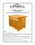
Assembly Instructions
Model 54228
Butcher Block Island
with Raised Panel Doors and Drop Leaf
GENERAL:
1. You have purchased model 54228.
2. Should you need assistance or need to replace a damaged or missing part simply give us a call M-F at
607-652-7321 from 7:30 am - 4:30 pm EST and we’ll send you the prepaid part via UPS usually that same
day! You may also email us [email protected].
3. Read the assembly instructions and the enclosed brochure before beginning assembly. Assembly is
easy if you read and follow the instructions step by step. See our website for assembly tips and videos.
4. Tools required: Phillips screwdrivers, medium and small; medium flat blade screwdriver and a hammer.
5. Drawer glides are sometimes pre-packed with screws, these are not used.
6. Directions (left/right, front/back) are given as facing the front of an assembled upright unit.
Parts List Model 54228
Center Shelf (1)
P/N CS-54228
Small Middle Shelf (2)
P/N SMS-54228
Drop Leaf (1)
P/N DL-54228
Side Panel (2)
P/N SP/HDL-54228
Table Top (1)
P/N TT-54228
Bottom Shelf (1)
P/N BS-54228
Glide Support (2)
P/N GLDSUP-54228
Drawer Bottom (1)
P/N DBOT-54228
29”
Drawer Front (1)
P/N DF-54228
Drawer Back (1)
P/N DBK-54228
Top Front Brace (1)
P/N B-38/2 1/2/TF-54228
Bottom Front Brace (1)
P/N B-38/2 1/2/BOT-54228
Divider Panel (2)
P/N DP-54228
Back Panel (1)
P/N BP-54228
Left Drawer Side (1)
P/N DS-54228L
Right Drawer Side (1)
P/N DS-54228R
Spice Rack Side Left (1)
P/N SR-54228L
Left Door (1)
P/N DOR-54228/LO
Left Center Door (1)
P/N DOR-54228/LC
Right Center Door (1)
P/N DOR-54228/RC
Right Door (1)
P/N DOR-54228/RO
Spice Rack Side Right (1)
P/N SR-54228R
Spice Rack Shelves (2)
P/N SRS-54228
Hardware for 54228
Drawer
1 3/4” Phillips Flat Head Bolt (8)
(8 are bronze for spice rack)
1 1/4” Phillips Flat Head #8 Screw (16)
P/N Drop Leaf Support (2)
Cabinet
Drawer Glide (1 Set )
(attach drawer back)
1 1/2” Phillips Flat Head #8 Screw (2)
(Used on “L” Brackets
and cabinet glides)
5/8 Wooden Disk (8)
Bastion Post (2)
5/8” Phillips Flat Hed #7 Screw (12)
Bastion Set Screw (2)
(Used on Cabinet Glides)
5/8” Phillips Flat Head #5 Screw (4)
(Attaches towel bar & spice rack)
3/16” Flat Washer (8)
“L” Bracket (4)
1” Phillips Flat Head #8 Screw (4)
Bastion Barrel Nut (2)
(Attaches
drawer handles)
1” Truss Head Machine Screw (4)
Polished Nickel Towel Bar (1)
(Attaches door handles)
7/8” Truss Head Machine Screw (8)
(Attaches drop leaf hardware)
5/8” Phillips Flat Head #8 Screw (26)
Towel Bar Post (2)
Nickel Handle (6)
(Divider Pin)
2” Long 3/16” DIA. Steel Pin (8)
(Door Pin)
Hinge (3)
Retainer Rods for Spice Rack (2)
1 1/2” Long 3/16” DIA. Steel Pin (8)
(Shelf Pin)
1” Long 3/16” DIA. Steel Pin (26)
10-24 Hex Nut (8)
(Brace Pin)
3/4” Long 3/16” DIA. Steel Pin (4)
Caster Socket (4)
Magnet Pack
Magnet (4)
Magnet Plate (4)
(Used on Magnet Plate)
1/2” Phillips Flat Head #4 Screw (4)
(Used on Magnet)
5/8” Pan Head Screw (8)
Locking Wheel Casters (2)
Wheel Casters (2)
STEP 1
A. Tap/insert ONE 1 1/2” pin into each end of all the doors. DON’T OVERDRIVE PINS! Pins should
stick up about 1/2” when seated.
B. Attach the magnet plate (may be stuck to magnet! ) with the 1/2” #4 screw to the top of the doors.
Bumps go toward the wood.
C. Attach door handles with 7/8” truss head machine screws.
1/2” #4 Flat Head Screw
(Included in magnet pack)
5/8” #8
7/8” Truss Head Screw
The counter sunk hole
goes out so the bumps
go toward the wood.
STEP 2
A. Take the 2 front braces and tap/insert one 3/4” steel pin into each end of both braces until seated.
About 3/8” will stick out when seated. OK if loose.
1 1/2” Pin
at bottom, space at top to clear magnet
B. Insert two 1” pins in bottom brace Flush
as shown.
Not used
Top Front Brace
Not used
1” Pin
3/4” Pin
Insert
Bottom Front Brace
STEP 3
Pilot holes in shelves
go toward back
Assemble Spice Rack
Fasten Shelves with
1 1/4” Phillips Flat Head
#8 Screw (Bronze)
Insert retainer
rods into holes
1 1/4” #8
STEP 4
A. Attach the Drawer Back to the Drawer Sides with two 1 1/2” #8 screws. There are left and right
drawer sides. Make sure the slots that run the length of the Sides are aligned with the slot in the
Drawer Back to accept the Drawer Bottom.
B. Slide in Drawer Bottom, best side up, to inside of drawer.
C. Take the 2 bastion posts, align the threaded end of the posts with the post holes located near the5/8” #5
ends of the inside of the Drawer Front. Tighten posts down until the solid shaft of the posts hits the
1” Truss Head Screw
wood. Back post out until the hole/screwdriver slot in end of post is parallel and in direct line with the
long edges of the Drawer Front.
D. Insert the barrel nuts into the nut access holes on the inside of the Drawer Sides with the threaded
ends of the nuts facing out. Take the Drawer Front and carefully insert the posts into the ends of
the Drawer Sides, through the sides of the nuts until seated. Push nut snug up against the wood in
the nut access hole toward the inside of Drawer Front. Hole should be slightly off-center toward the
Drawer Front. Insert the set screw and tighten down.
The ends of the sides should be tight against the inside
Note: Drawer Back is shorter than
1 1/2” #8
Drawer Front.
the Drawer Sides to allow clearance
for Drop Leaf Supports
E. Attach the drawer handles with 1” Truss head
machine screws.
F. Attach the drawer glides
(left and right) to the Drawer
Sides using two 5/8” #5
screws per side. Wheels
go toward Drawer Back
and are up. The end
with no wheels
should touch the
Drawer Front.
5/8” #5
1” Truss Head Screw
See next page to learn how the bastion fastening system works.
Also see our video on the Bastion Fastening System at www.catskillcraftsmen.com
TIPS ON HOW THE BASTION FASTENING SYSTEM WORKS
1. The Bastion fastening system consists of a steel post (threaded on one end with a hole
through the shaft on the other end); a Barrel Nut (cylindrical barrel-shaped with threaded
open end & holes through the sides); and a Set Screw (Phillips slot on one end, pointed on
the other)
2. To attach Posts: A) Dip threads of Post in vegetable oil. B) Align threaded end of Post
with hole in wood, tap on slotted end with hard hammer until threads enter, then tighten
down using a flat head screw driver or the provided allen wrench (See the Illus. Bas. 3 for
alternate seating methods). DO NOT TRY TO HAMMER THE POST ALL THE WAY IN AS IT
WILL STRIP THE POST HOLE. C) When solid shaft of Post hits wood, back out
approximately ½ turn until the hole in the posts is properly aligned as per step by step
directions. For example: the holes in the posts on the inside of the drawer front will be
parallel with the long length of the drawer front when properly seated.
Illustration Bas. 1
WRONG!
Post needs to be screwed deeper.
3. A) Place a Barrel Nut into the nut access hole, so that the threads in the nut face out.
The small notches on either side of the nut opening, indicate the location of the holes
through the sides of the nut. B) Insert the posts through the end of the braces (or drawer
sides); through the holes in the sides of the nut. When properly aligned, you will see the hole
in the post inside the barrel nut. Post hole should be slightly off-center toward the wood.
WRONG!
Post needs to be backed out.
4. Insert the Set Screw into the threaded end of the nut and tighten down. The tip of the Set
Screw will seek the center of the hole in the Post as it is tightened down, forcing the Nut
toward the main shaft of the Post. This is what tightens the wooden parts together. Set
screws should thread easily – DON’T CROSS THREAD! If Set Screw doesn’t thread easily,
check position of the hole in Post.
CORRECT!
Set screw secures post properly.
5. If the wooden parts are not tight against each other, the Post needs to be screwed a half
turn at a time until wood joints are tight.
Illustration Bas. 3
Illustration Bas. 2
Step 1
Step 2
Allen Wrench Provided
See video on our website!
If you have any questions regarding assembly or missing or damage
parts, call our customer support number:
607-652-7321 or 888-732-7321.
Customer Support Hours are 8am-5pm Mon. - Fri. Eastern Time zone.
STEP 5
A. Attach a Glide Support Stick to the top of each Side Panel using 1 1/4” #8 screws. The
countersunk holes (reamed out) in the stick are positioned as in illustration 1 so that the glide holes
are toward the lower edge. Sticks should be flush with top of panel.
B. Attach the cabinet glide of the Drawer Glides to the Glide Support Stick using 5/8” #7 flat head
screws. Left glide to left Side Panel, right glide to right Side Panel. The glides look almost alike
however, the right glide (as you face the cart) has a rolled lip at the top of the glide that keeps the
drawer glide wheel in place. Line up the holes in the glides so that the end with the wheel comes flush
with the front edge of the Table Top Stick.
C. Attach the “L” brackets to the top of the glide supports using 5/8” #7 screws. Use hole rather than
slot.
Note: Glides are marked right/left with imprint behind wheel.
5/8” #7 Screw
TOP
1 1/4” #8 Screw
TOP
5/8” #7 Screw
STEP 6
A. Lay Back Panel flat on a smooth surface with holes up.
B. Attach Side Panels with 1 3/4” machine screws (bolts) and hex nuts. After inserting bolts(s) thru the
holes in the Side Panels, thru the holes in the long edges of the Back Panel, place a hex nut on the
tip of your finger, align nut with bolt and tighten.
C. The back banel is flush with bottom of side panels.The back panel is 1 1/4” shorter than the side
panels, leaving room at the top for drop leaf supports and hinges.
D. Look ahead to step 7 which shows side panels attached to back panel.
1 3/4” Bolts
E. Insert 1” pins into back panel as shown.
Note: Wheel on glide is
to the front of the unit
1 3/4” Bolts
Note: Wheel on glide is
to the front of the unit
Nut
Nut
1” Pin
1” Pin
STEP 7
Bottom Brace
Assembly
A. Secure bottom brace
with 1 3/4” bolts/nuts as
shown.
B. Insert 1” pins into
the side panels as shown.
1” Pin
Nut
1” Pin
1 3/4” Bolts
Nut
1 3/4” Bolts
STEP 8
Door Assembly
Washer
Slide top front brace down into position to secure doors. Fasten with 1 3/4” bolts and nuts as shown.
Nut
1 3/4” Bolts
STEP 9
Magnet
Note: You may find it easier
to lay the unit on it’s back.
No pilot holes as softwood.
5/8” Pan Head Screws
A. Stick magnet to magnet plate on a door.
B. With all other doors open, close the door. The magnet should be positioned over the wooden block
on the bottom of the top front brace. Hold the magnet in place with your thumb, and open the door.
The magnet will be in the correct position on the block.
C. Secure magnet with the two pan head screws in the magnet packet. Center screws in the slot in
the magnet. This will allow adjustment later, if needed.
D. Repeat these steps for all the doors.
STEP 10
A. Lay the cart on it’s back. Insert and tap caster sockets with hammer until the teeth grab the wood.
DON’T POUND SOCKET FLAT OR CASTER SHAFT WILL NOT ENTER.
B. Insert casters and seat by pushing straight
downward with heel of your hand, or tap into
place with a hammer. Don’t be afraid to give
them a good downward whack on the solid
metal part of the caster!
C. Locking wheels usually go on front.
STEP 11
A. Upright unit.
B. Determine if you want the Spice Rack on the left or right Side Panel. The Handle/Towel Bar will
go on the other. Then attach the Spice Rack to the Side Panel with two 1” #8 screws from inside
the panel. Place
a washer over the
screw so that so
that the head won’t
pull through the side
panel. Use the pilot
holes in the top
shelf of spice
rack.
C. Attach Towel
Bar to the other
Side Panel with
1” #8 screws from
inside the Side Panel.
Place a washer over
each screw.
STEP 12
A. Angle the Bottom Shelf as necessary
to pass it through the opening in the
cabinet top until it rests on the pins
installed in steps 2, 6, and 8.
STEP 13
A. Tap 1” pins into the 4 sets of holes in the
Back Panel.
B. Just above the Bottom shelf on the inside of
the Bottom Front Brace there are two sets of
holes. Tap 1” pins into these holes.
Edge banding toward front of unit.
2” Pins
C. On the Inside face of the Top Front Brace
there is a hole adjacent to each of the magnet
blocks for the outside doors. Tap one 1” pin
into each hole.
D. Choose the height you want your
middle shelves, then tap the 2” pins in
accordingly on the Cabinet Dividers.
E. Slide the Cabinet Dividers
between the sets of pins in the
Back Panel and the pins in the
Front Braces until dividers rest
on the Bottom Shelf.
NOTE: Eight 2” pins are provided
in case you want the center middle
shelf & the side middle shelves at
different heights.
1” Pins
Divider
in place
STEP 14
Drop Leaf Assembly
A. Assemble top by placing the top and drop leaf upside down on a smooth flat surface. Install hinges
using 5/8” #8 screws. The longer part of the hinge goes on the drop leaf with the short part on the cart
top. Fasten the drop leaf supports using 5/8” #8 screws. See illustration 14A.
5/8” #8
ILLUSTRATION 14A
Marking an X with a pencil on the pilot holes under
the tabletop will help to line up the pilot holes with
the L Brackets in step 15.
ILLUSTRATION 14B
STEP 15
A. Place the Cart Top on the cabinet. Open
the outside doors. Maneuver the Cart Top so
that the ( X ) marks/pilot holes in the bottom
of the Top align with the holes in the “L”
brackets. Secure top to “L” brackets with 5/8”
#7 screws.
5/8” #7
STEP 16
A. Slide the drawer into the front of the cart. If necessary, adjust top front brace so that drawer
moves freely. Then retighten all bolts/nuts.
B. Tap in the 5/8 wooden plugs into the holes on the legs.
C. Install small middle and center shelves simply by sliding them in, edge banding out.
For continued beauty and long life of your
Catskill Craftsmen cart, we recommend
Catskill Craftsmen’s Butcher Block Oil.
Our Butcher Block Oil is available directly from Catskill Craftsmen’s factory. For
one eight ounce (8 fl. oz.) bottle, which
is sufficient for two applications, simply
send $6.95 along with the completed
coupon to the address below. Visit us
online at www.catskillcraftsmen.com to
browse our assortment of butcher block
care products. Visa and Mastercard are
accepted online .
BUTCHER BLOCK OIL COUPON
Please send me______# of bottle(s) of the
Catskill Craftsmen Butcher Block Oil at $6.95
per bottle. My check or money order is
enclosed for a total of $____________.
Item code: 54228
Name________________________________
Address______________________________
City_________________________________
State____________ Zip_________________
Catskill Craftsmen, Inc.
15 West End Ave.
Stamford, NY 12167-1296
Please make checks payable to Catskill Craftsmen
Inc. 15 West End Ave., Stamford, NY 12167-1296