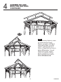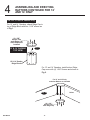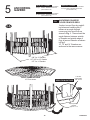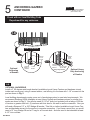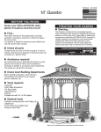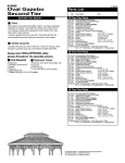
1
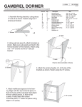
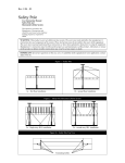
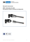
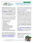
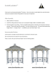
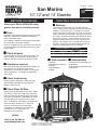
Revision:
Run:
San Marino
1000 Ternes Drive
Monroe MI, 48162
Toll-Free 1-800-437-0784
10’,12’ and 14’ Gazebo
- BEFORE YOU BEGIN Always wear OSHA-APPROVED safety
glasses throughout assembly process
■ First...
Read these instructions thoroughly before you begin
assembly. Assembly is easiest if you follow the
steps in the order shown.
In a drawing, a dotted line represents a part hidden
from view (like a part under a panel).
Lumber is graded from only one side. Check the part
for the most attractive face and make sure to face it
to the outside.
2-12-07
Made in the U.S.A.
- TREATING YOUR GAZEBO ■ Staining...
This Gazebo is constructed of a long-lasting western
cedar. Untreated cedar exposed to sunlight will eventually
weather to a silver-grey color. To validate your warranty
and to help keep the original red color, read your warranty
page on maintaining your Gazebo. Applying a minimum of
two coats of oil based penetrating stain WITHIN 30 DAYS
(required by warranty). Some sanding to remove rough
edges and natural wood stains may be required prior to
staining. Your Gazebo roof is not waterproof unless it is
shingled. Caulking the roof seams before shingling will
improve the water resistance of your Gazebo.
STAIN REQUIREMENTS FOR GAZEBOS
Add for Options
■ Check all parts
Compare parts you have to the list on page 2. If a
part is missing, circle the part in question in the
parts list and call us toll-free at 1-800-437-0784.
■ Assistance required
We recommend that you assemble this Gazebo on
level ground in the location it will be used.
Assistance is necessary to handle, fit, and secure
some components. Two people are needed for
some steps.
SIZE
10'
12'
14'
# OF GALLONS
2
3
4
■ Tools required
❑ Hammer
❑ #2 Phillips Screwdriver
❑ Ladder
❑ Tape Measure
❑ Pencil
■ Check local zoning
Before starting construction, check with your
local building code official for any required
permits, variances, etc.
■ Check Floor Kit Size
Before starting construction on your floor, make
sure that you check in the instruction manual to
make sure that you are building the correct size
floor kit for your Gazebo. San Marino 10’ actual
floor size has to be a minimum of 9’-3” flat to
flat or 10’ Diameter. San Marino 12’ actual floor
size has to be a minimum of 11’-8-3/4” flat
to flat or 13’ Diameter is recommended.
San Marino 14’ actual floor size has to be
a minimum of 14’-2” flat to flat or 15’
Diameter is recommended.
#16695
Visit us on the Web at:
www.HandyHome.com
San Marino 10’- 8 sided Gazebo shown with optional Floor Kit (Not Included)
San Marino 12’- 10 sided Gazebo (not shown)
San Marino 14’- 12 sided Gazebo (not shown)
FLOOR
1
1
1.5
SCREEN KIT
.5
.5
1
■ Optional tools
❑ Electric Drill w/ #2 Phillips Tip
❑ Nail Pouch
❑ 1/8” Drill bit-for predrilled holes
❑ Wood Glue
San Marino 10’, 12’ and 14’ Gazebo
8-Sided
12-Sided
10-Sided
■ Parts List San Marino 10’
❑ 7 pcs. Pre-assembled Wall Panels 44-3/4” x 82-1/2”
❑ 1 pc. Pre-assembled Door Panel 44-3/4” x 82-1/2” with Spacer
❑ 1 pc. Roof Finial
❑ 1 pc. Ridge Block 8-Sided
❑ 1 pc. Metal Roof Cap
❑ 8 pcs. Plywood Triangular Roof Panels
❑ 8 pcs. Rafters
2 x 4 x 62-3/4”
❑ 8 pcs. Plywood Gusset Brackets
❑ 7 pcs. Sill Plates Notched
2 x 4 x 40-1/4”
❑ 8 pcs. Plywood Fascia
5/8” x 3-1/2” x 46-7/8”
❑ 8 pcs. Fascia Trim in Hardware 3/8” x 1-1/2” x 3-3/4”
■
Hardware Kit
❑
#8 - 3” Screw, #8 - 1-5/8” Screw, #8 - 2-1/2” Screw, 6d-2” Nail, 4d-1-1/2”
Finish Nail, 3/4” Roofing Nail, 1” Roofing Nail
SPACER
PRE-ASSEMBLED
WALL PANEL
■ Parts List San Marino 12’
PRE-ASSEMBLED
DOOR PANEL
❑ 9 pcs.
❑ 1 pc.
❑ 1 pc.
❑ 1 pc.
❑ 1 pc.
❑ 10 pcs.
❑ 10 pcs.
❑ 10 pcs.
❑ 9 pcs.
❑ 10 pcs.
❑ 10 pcs.
❑ 2 pcs.
❑ 18 pcs.
■
❑
Pre-assembled Wall Panels 44-3/4” x 82-1/2”
Pre-assembled Door Panel 44-3/4” x 82-1/2” with Spacer
Roof Finial
Ridge Block 10-Sided
Metal Roof Cap
Plywood Triangular Roof Panels
Rafters
2 x 6 x 78-3/8”
Plywood Gusset Brackets
Sill Plates Notched
2 x 4 x 40-1/4”
Plywood Fascia
5/8” x 3-1/2” x 46-3/8”
Fascia Trim in Hardware
3/8” x 1-1/2” x 3-3/4”
Ridge 10 Sided Cover
1/2” x 5-1/4”
Corbels
2 x 4 x 14”
Hardware Kit
ROOF FINIAL
SILL PLATE
PLYWOOD GUSSET
BRACKETS
10' RIDGE BLOCK
#8 - 3” Screw, #8 - 1-5/8” Screw, #8 - 2-1/2” Screw, 6d-2” Nail, 4d-1-1/2”
Finish Nail, 3/4” Roofing Nail, 1” Roofing Nail
12' AND 14'
RIDGE BLOCK
COVER
■ Parts List San Marino 14’
❑ 11 pcs. Pre-assembled Wall Panels 44-3/4” x 82-1/2”
❑ 1 pc. Pre-assembled Door Panel 44-3/4” x 82-1/2” with Spacer
❑ 1 pc. Roof Finial
❑ 1 pc. Ridge Block 12-Sided
❑ 1 pc. Metal Roof Cap
❑ 12 pcs. Plywood Triangular Roof Panels Small
❑ 12 pcs. Plywood Roof Panels Large
❑ 12 pcs. Rafters
2 x 6 x 92-7/8”
❑ 12 pcs. Plywood Gusset Brackets
❑ 11 pcs. Sill Plates Notched
2 x 4 x 40-1/4”
❑ 12 pcs. Plywood Fascia
5/8” x 3-1/2” x 46”
❑ 12 pcs. Fascia Trim in Hardware
3/8” x 1-1/2” x 3-3/4”
❑ 2 pcs. Ridge 12 Sided Cover
1/2” x 7-1/8”
❑ 22 pcs. Corbels
2 x 4 x 14”
❑ 12 pcs. Temporary Brace
6”x14”
PLYWOOD FASCIA
12' AND 14'
RIDGE BLOCK
CORBELS
12' AND 14'
ONLY
10' AND 12'
ROOF PANEL
FASCIA TRIM
METAL ROOF CAP
■ Hardware Kit
14' ROOF PANEL
2 PIECES
NATIONAL STANDARD LUMBER SIZES
❑ #8 - 3” Screw, #8 - 1-5/8” Screw, #8 - 2-1/2” Screw, 3/4” Screw, 6d-2” Nail,
Nominal size
1x4
2x4
2x2
2x6
4d-1-1/2” Finish Nail, 3/4” Roofing Nail, 1” Roofing Nail
2
Actual size
= 3/4" x 3-1/2"
= 1-1/2" x 3-1/2"
= 1-1/2" x 1-1/2"
= 1-1/2" x 5-1/2"
San Marino
1
FLOOR SYSTEM (Floor systems not supplied with kit)
YOU MUST BUILD YOUR GAZEBO ON A FLOOR SYSTEM.
SITE PREPARATION
• Site must be properly leveled.
• Site should have natural drainage to
eliminate puddling under and around the
building.
• Site should be covered with plastic film
to discourage grass growth under the
building and to serve as a vapor barrier.
Before assembling your gazebo, you
must first construct a floor system. You
can:
A. Purchase our optional pre-cut Floor Kit.
B. Purchase materials to cut and build
your own wooden floor.
NOTE: Our Precut Floor Kits have been
designed for normal residential use. It is
characteristic for the floor panels to
deflect (flex) during normal use. If you
intend to store very heavy objects in your
Gazebo, you may want to consider
adding floor joists to reduce the span.
Wooden Floor Kit
OR
C. Install a 4” concrete slab floor system.
IF USING CONCRETE SLAB FLOOR
SYSTEM
• Construct 4” Concrete Slab Floor
System.
• Upon completion of above steps, skip
“Floor Kit Assembly” section and proceed
to Step #2: Assembling Wall Panels.
Concrete Slab Floor System
San Marino
3
1
WOOD FLOOR SITE PREPARATION
For optional pre-cut floor kit, follow assembly instructions included with floor kit.
It is important to have a solid, flat and level foundation for your Gazebo.
Carefully consider the recommendations listed below prior to creating your foundation.
Wood Floor Dimensions
LEVEL GROUND INSTALLATION
Remove dirt to allow for Floor Frame. Shim outside of frame
corners as needed. Follow local codes for anchoring requirement
or see local home center for recommendation.
10' Floor
111"
Flat to
Flat
60"
Point to
Center
UNEVEN GROUND INSTALLATION
46"
Use treated 4 x 4 posts or concrete piers on each corner and in
center of deck. Hole depth will vary according to local building
codes. Cut center post 1-1/2” shorter to allow for Base Plate as
shown in Fig.1. Nail or screw Deck to top of 4 x 4 posts. Use
Simpson Tie or similar for each Concrete pier. See local home
center.
12' Floor
140-3/4"
Flat to
Flat
74"
Point to
Center
HARD SURFACE INSTALLATION
Do Not Use the Base Plate in our Floor Kit for Hard
Surfaces. Measurements given on the illustration are
1-1/2” larger than the outside dimensions of the Gazebo.
You may choose to make your own floor larger than the
dimensions given. Step 5 shows you how to anchor
your gazebo.
(Hardware not included in Kit.)
46"
14' Floor
173"
Flat to
Flat
Fig.1
89-9/16"
Point to
Center
86-1/2"
Middle to
Center
46-3/8"
Center of Floor Kit
WOOD FLOOR KIT
J2
J3
WOOD FLOOR KIT
J2
Base Plate
1-1/2"
GRADE
Minimum of
6" of Air Space
GRADE
4x4
Treated Post
or 12"x12"
Concrete Pier
NOTE:
1. All below grade material
to be treated for below
grade application.
2. All above grade material
is Cedar.
4x4
Treated Post
or 12"x12"
Concrete Pier
42" or Code
4x4
Treated Post
or 12"x12"
Concrete Pier
CONCRETE PAD
FOOTING
8" x 4" Diameter
for Treated Post
4
San Marino
1
CONCRETE SLAB SITE PREPARATION
It is important to have a solid, flat and level foundation for your Gazebo.
Carefully consider the recommendations listed below prior to creating your foundation.
CONCRETE SLAB OR HARD SURFACE
INSTALLATION
Fig.1
Measurements given on the Fig. 1 Concrete Slab Dimensions illustration are 1-1/2” larger than the outside dimensions of the Gazebo. You may choose to make your
concrete slab larger than the dimensions given. Step 5
shows you how to anchor your gazebo.
(Hardware not included in Kit.)
Concrete Slab Dimensions
111"
Flat to
Flat
10' Floor
60"
Point to
Center
Dig out 4” of ground for concrete and 4” for sand/gravel
(per local code) so it is level. Finish digging 12” wide by
12” deep (per local code) continuous footing around the
perimeter of the pad. Use wood forms around the
perimeter of gazebo foundation area. Use rebar as
needed. Pour concrete and make sure all points of the
concrete top are level and see Fig 2.
46"
12' Floor
140-3/4"
Flat to
Flat
74"
Point to
Center
46"
14' Floor
173"
Flat to
Flat
89-9/16"
Point to
Center
Fig.2
The top of your concrete pad
should be 1" minimium above grade.
4" Concrete pad
4" Sand or Gravel
12"x12"
Continuous
Footing
San Marino
5
86-1/2"
Middle to
Center
46-3/8"
2
ASSEMBLING
WALL PANELS
PARTS LIST 10’ GAZEBO
PARTS LIST 14’ GAZEBO
❑ 7 pcs. Pre-assembled Wall Panels
❑ 1 pc. Pre-assembled Door Panels
❑ 11 pcs. Pre-assembled Wall Panels
❑ 1 pc. Pre-assembled Door Panels
PARTS LIST 12’ GAZEBO
❑ 9 pcs. Pre-assembled Wall Panels
❑ 1 pc. Pre-assembled Door Panels
2-A:
Select desired Door location and position Wall
Panels on ground around foundation as shown
in Fig. 2-A.
2-A
If you are constructing the 12’ Gazebo, please
allow for two additional wall sections when
laying out your walls.
If you are constructing the 14’ Gazebo, please
allow for four additional wall sections when
laying out your walls.
Door Spacer
DO NOT
REMOVE
NOTE: Wall Panels have beveled edges.
The widest bevel will face the ground and
is the outside of the Gazebo wall as shown
in Fig. 1.
Fig.2
Flush at top
Fig.1
Widest Bevel
on Ground
2-B:
2-B
Stand up two adjoining Wall Panels and attach
them together using five 3” screws as shown in
illustration 2-B. HINT: Start in middle and
work up and down. Make sure that the two
Wall Panels are flush at the top as shown in
Fig. 2. Connect all Wall Panels in this same
manner, making sure not to remove the Door
spacer at this time.
5-3" Screws
Note: Use wood glue (not included) between
Wall Panels for added strength and to meet
some local building codes.
6
San Marino
3
INSTALLING
GUSSET
BRACKETS
PARTS LIST 10’ GAZEBO
PARTS LIST 14’ GAZEBO
❑ 8 pcs. Plywood Gusset Bracket
❑ 12 pcs. Plywood Gusset Bracket
PARTS LIST 12’ GAZEBO
❑ 10 pcs. Plywood Gusset Bracket
VIEW FROM INSIDE
Note: Use wood glue (not included)
between Wall Panels and Gussets
for added strength and to meet
some local building codes. Temporarily install all gussets with 1-5/8”
screws to align walls. Remove one
gusset, apply glue, install all
screws. Continue for all Gussets.
Fig.1
FLUSH
3-A
Gusset Bracket
VIEW FROM OUTSIDE
Fig.2
2-1/2"
(6.3cm)
Rough sawn
Cedar side
facing down
(8) 1-5/8"
Screws into
each Gusset
Gap may vary in
between Gussets
3-A:
Install Gusset Brackets with Rough sawn Cedar
side facing down using eight 1-5/8” screws for each
Gusset. Make sure that the Gusset Bracket is flush
to the inside of the Wall Panel and that the inside
corner is directly over inside corner of Wall Panel
as shown in Fig. 1. The Gusset Bracket should
overhang the outside edge of the Wall Panel by 21/2” as shown in Fig. 2. This step may require
some pulling of the Wall Panel to bring it into
proper position. Tip to tip measurement on Gussets is 46-7/8” for 10’ Gazebo and 46-3/8” on 12’
Gazebo and 46” for 14’ Gazebo. The gap between
Gussets may vary.
San Marino
7
4
RAFTER AND RIDGE
BLOCK ASSEMBLY AND
ERECTING RAFTERS
If you are assembling a 12 or 14’ Gazebo, please
begin with step 4-B, if you are assembling a 10’
Gazebo, please go to step 4-A.
❑ 12 pcs. Rafters 2 x 4 x 92-7/8”
❑1 pc.
Ridge Block-12 Sided
❑ 2 pc. Ridge Cover-12 Sided
PARTS LIST 12’ GAZEBO
❑ 10 pcs. Rafters 2 x 6 x 78-3/8”
❑ 1 pc. Ridge Block - 10 Sided
❑ 2 pc. Ridge Cover-10 Sided
For a 10’ Gazebo, assemble Rafters (with predrilled holes facing up) by joining two Rafters on
opposite sides to Ridge Block (with predrilled
holes in Ridge Block facing down) using two 3”
screws through predrilled hole in top of Rafter.
Once two Rafters are connected to Ridge Block,
carefully turn over and attach two 3” screws
through predrilled holes in Ridge Block into
Rafter. The 10’ San Marino has eight Rafters.
Do not assemble remaining rafters at this time,
continue with step 4-C.
10' GAZEBO
TOP VIEW
3" Screw
Rafter
PARTS LIST 14’ GAZEBO
4-A:
4-A
Flush
at top
PARTS LIST 10’ GAZEBO
❑ 8 pcs. Rafters 2 x 4 x 62-3/4”
❑ 1 pc. Ridge Block-8 Sided
Rafter
10' Gazebo
Ridge Block Eight
Pre-Drilled Holes
Facing Down
3" Screw
4-B
12' & 14' GAZEBO
TOP VIEW
BOTTOM VIEW
1/2"
Mark
3" Screws
4-B:
For 12’ and 14’ Gazebo, assemble Rafters by
joining two Rafters on opposite sides to Ridge
Block using two 3” screws through predrilled hole
in top of Ridge Block. Leave a 1/2” gap between
the top of the rafter and the Ridge block.
Once two Rafters are connected to Ridge Block,
carefully turn over and attach two 3” screws
through predrilled holes in Ridge Block into
Rafter. The 12’ has ten Rafters and the 14’ has
Twelve Rafters. Do not assemble remaining
rafters at this time, continue with step 4-C.
Rafter
Maintain
1/2"
Space
Rafter
12' & 14' Gazebo
Ridge Block Pre-Drilled
BOTTOM VIEW
8
3" Screw
San Marino
4
RAFTER AND RIDGE
BLOCK ASSEMBLY
CONTINUED
4-C
VIEW FROM BOTTOM
VIEW FROM TOP
Fig.2
Fig.1
(2) 3"Screws
at slight angle
Centered over corner
of Gusset Bracket
4-C:
Carefully lift the Rafter and Ridge Block assembly on top of the Gusset Brackets at opposite
corners of the Gazebo. Place Rafter Ends at center of outside corner of Gusset Bracket as
shown in Fig. 1. Once Rafter is in place, attach to Gusset Bracket with two 3” screws through
predrilled holes from underside of Gusset Bracket into bottom of Rafter as shown in Fig. 2.
NOTE: Adjust Wall corners in or out to fit.
San Marino
9
4
ASSEMBLING AND
ERECTING RAFTERS
CONTINUED
4-D
4-D:
Install remaining Rafters by inserting screws through Gusset
Bracket, as shown in 4-C Fig. 2,
while holding Rafter in position.
Install 3” screw through top of
Rafter or Ridge Block as shown in
4-A or 4-B top view. Once all
Rafters are in place, install 3”
screws in underside of Ridge
Block into Rafters as shown in
4-A or 4-B bottom view.
10
San Marino
4
ASSEMBLING AND ERECTING
RAFTERS CONTINUED FOR 12’
AND 14’ ONLY
4-E: For 12’ and 14’ Gazebo Only
For 12’ and 14’ Gazebos, attach Ridge Cap to
top of Ridge Block with four 1-5/8” screws as
in Fig.1.
(4) 1-5/8"
Screws into
each Ridge Cap
after Rafters are
installed
12' & 14' GAZEBO
TOP VIEW
Fig.1
12' & 14' Gazebo
Ridge Block
For 12’ and 14’ Gazebos, install bottom Ridge
Cap cover with (4) 1-5/8” Screws and shown in
Fig.2.
For 12' and 14' Only
and after Rafters are Installed
Fig.2
(4) 1-1/4"
Screws into
each Ridge Cap
San Marino
11
Rafter
5
ANCHORING
GAZEBO
PARTS LIST 10’ GAZEBO
❑ 1 pc. Assembled Side Wall and Rafters
❑ 8 pcs. Metal “L” Brackets and Screws
(Not included in Kit)
PARTS LIST 14’ GAZEBO
❑ 1 pc. Assembled Side Wall and Rafters
❑ 12 pcs. Metal “L” Brackets and Screws
(Not included in Kit)
PARTS LIST 12’ GAZEBO
❑ 1 pc. Assembled Side Wall and Rafters
❑ 10 pcs. Metal “L” Brackets and Screws
(Not included in Kit)
5-A: ANCHORING ON WOOD
FLOOR OR WOOD DECK
Anchor to wood floor by predrilling holes and installing two 3”
screws at an angle through
corner post into wood floor as
shown in Fig. 1. There should be
equal distance between outside
of Gazebo and outside edge of
floor all around Gazebo as shown
in Fig. 1.
10’, 12’ and 14’ Gazebos are
anchored in the same manner.
5-A
108" for 10' Gazebo
137-3/4" for 12' Gazebo
167" for 14' Gazebo
WOOD FLOOR OR DECK
10' Floor shown
VIEW FROM OUTSIDE
3" Screws
Predrill holes
with 1/8" bit
Fig.1
Equal space on
all sides
Approx. 1-1/2"
12
San Marino
5
ANCHORING GAZEBO
CONTINUED
PARTS LIST
❑ Assembled Side Wall and Rafters
❑ Anchor or Brackets and Screws
(Not included in Kit)
Check with our local Building Code
Department for any variances.
5-B
VIEW FROM INSIDE
Optional
Bolts
1/2"x3"
Optional
Anchor
Screws
Fig.2
Optional
Anchoring
of Gazebo
Fig.3
Optional
Metal "L"
Bracket
Optional
Anchor
Bracket
1-1/4"
Screws
1/2" Concrete
Anchor Bolt
Heavy Duty Anchors
Optional Heavy
Duty Anchoring
of Gazebo
5-B:
OPTIONAL ANCHORING
Install a 2” 90 degree metal angle bracket (available at most Home Centers and hardware stores)
inside each corner post, using a cement anchor, and affixing it to the base with 1-1/4” screws into the
post as shown in Fig. 2.
Local building departments require some sort of anchoring system to meet wind requirements. We
recommend Simpson HD2A (available at most Home Centers and hardware stores) or similar for a
anchor as shown in Fig. 3. You will also need (2) 1/2”x3” bolts (not included) with a rating of 500 lbs.
of tension or greater each bolt, (2) washers and nuts also for the wall to anchor connection. Also you
will need a Simpson 1/2” or 5/8” Wedge-All anchor, Titen Hd or similar (available at most Home Centers and hardware stores) for the anchor to concrete connection. If you have a wood floor you would
need a 12” long Wedge-All and a 6” long for a Concrete slab. Anchors need to be imbedded at least
4-1/2” into concrete.
San Marino
13
6
PARTS LIST 10’ GAZEBO
❑ 8 pcs. Plywood Triangular Roof Panels
INSTALLING ROOF PANELS
FOR 10’ & 12’ GAZEBO
PARTS LIST 12’ GAZEBO
❑ 10 pcs. Plywood Triangular Roof Panels
* For 14’ Models, continue with page 15.
NOTE: Make certain the rough cedar sawn
side of each Roof Panel is facing
down during assembly.
2" Nail
Center Panels on or in
between 3/4" Marks
3/4"
Marks
Fig.1
3/4"
6-A
Fig.2
3/4"
Plywood
side
Roof Panels Should
Overhang about 1"
10' or 12' Roof Panel
Rough sawn
Cedar side
3/4"
2" Nail
6-A:
When installing the Roof Panels, the rough sawn cedar side should be facing to the inside of your
Gazebo. Along each Rafter, place a mark 3/4” in on each Rafter to help center Roof Panels as shown
in Fig. 1 and Fig. 2. Set first Roof Panel in place on top of Rafters, making top of Roof Panels line up
where Rafter and Ridge Block meet and nail with one 2” nail at the top of Roof Panel. Once top is
nailed, make sure Roof Panel at bottom is centered between 3/4” marks on both Rafters. Once Roof
panel is aligned nail with two 2” nails at bottom corners. For 10’ and 12’, continue on page 16.
14
San Marino
6
PARTS LIST 14’ GAZEBO
❑ 12 pcs. Plywood Triangular Roof Panels Small
❑ 12 pcs. Plywood Triangular Roof Panels Large
❑ 12 pcs. Temporary Brace
6”x14”
INSTALLING ROOF PANELS
FOR 14’ GAZEBO ONLY
NOTE: Make certain the rough sawn cedar side of each
Roof Panel is facing down during assembly.
2" Nail
Temporary
Brace connected with
(6) 3/4" screws
Plywood
side
6-A
Fig.2
Center Panels on or in
between 3/4" Marks
3/4"
Marks
Plywood
side
3/4"
Fig.1
2" Nail
3/4"
Upper
Panel
Mark all Roof Panels
1" from bottom
Fig.3
Lower
Panel
1"
3/4"
Plywood
side
Plywood
side
Mark all roof panels
1" From Bottom
on Cedar side
Rough sawn
Cedar side
2" Nail
6-A:
Place roof panel pieces as shown in Fig. 1 with Plywood side up. Place 6x14" temporary brace
between to pieces and attach with (6) 3/4" screws. When installing the Roof Panels, the rough sawn
cedar side should be facing to the inside of your Gazebo. Along each Rafter, place a mark 3/4” in on
each Rafter to help center Roof Panels as shown in Fig. 2 and Fig. 3. Next mark, on cedar side, all
Roof Panels 1” from bottom as shown. Set first Roof Panel in place on top of Rafters, making Bottom
1” mark of Roof Panels line at Rafter ends and nail with one 2” nail at each corner of Roof Panel.
Once bottom is nailed, make sure Roof Panel at top is centered between 3/4” marks on both Rafters.
Once Roof panel is aligned nail with one 2” nail at top corner.
San Marino
15
6
INSTALLING ROOF
PANELS CONTINUED
5
4
6-B
6
3
7
8
2
1
2
14" Gazebo Roof Panels are 2 pcs.
2" Nails every 8"
once all Roof Panels are in place
6-B:
Follow the same steps as in 6-A to install all
remaining Roof Panels, only temporarily nailing in place. Once all Roof Panels are in place
and fit properly on your Gazebo, then nail every
8” with 2” nails. 10’ model has eight Roof Panels,
12’ model has ten Roof Panels and 14’ has 12
Roof Panels. For 14’ Gazebo models, remove
temporary brace when all roof panels are in
place and secured with 2” nails every 8”.
16
San Marino
7
INSTALLING
FASCIA
PARTS LIST 10’ GAZEBO
❑ 8 pcs. Fascia 5/8” x 3-1/2” x 46-7/8” Plywood
❑ 8 pcs. Fascia Trim 3/8” x 1-1/2” x 3-3/4”
PARTS LIST 14’ GAZEBO
❑ 12 pcs. Fascia 5/8” x 3-1/2” x 46” Plywood
❑ 12 pcs. Fascia Trim 3/8” x 1-1/2” x 3-3/4”
PARTS LIST 12’ GAZEBO
❑ 10 pcs. Fascia 5/8” x 3-1/2” x 46-3/8” Plywood
❑ 10 pcs. Fascia Trim 3/8” x 1-1/2” x 3-3/4”
Rafter End
Fig.1
Rough sawn
Cedar side
3/4"
Mark
7-A:
Place a mark 3/4” in on end of Rafter as shown in Fig. 1. Center
Fascia on Wall Panels in between corners and 3/4” marks and butt
Fascia to bottom of Roof Panels. Tack on the Fascia to the Gusset Brackets at each corner with one 1-1/2” Finish Nails. Continue attaching remaining seven pieces of Fascia for 10’ Gazebos,
nine pieces for 12’ Gazebos and eleven pieces for 14’ Gazebos.
Once all Fascia are in place, finish nailing along bottom edge and
top of Roof Panel with five more 1-1/2” Finish Nails. 10’,12’ and 14’
Gazebo Fascia are installed in the same manner.
Attach Fascia Trim over seam where two Fascia panel pieces meet
and attach with two 1-1/2” Finish nails through Fascia Trim into
Fascia Panel as shown in Fig. 2. Pre-drilling is recommended.
Fascia butts up to
Roof Panel
Rafter
3/4"
7-A
cia
s
Fa
Fascia
Fig.2
Two-1-1/2"
Finish Nails to hold
all Fascia in place
then, once all
Fascia in place,
add five more
1-1/2" Finish Nails.
San Marino
Roof Panel
Fascia
17
Attach Fascia Trim with
two 1-1/2" Finish Nails
Roof Panel
Fascia
Note: If installing a Screen Kit, skip Step 8 and refer to Screen Kit instruction manual
before going to Step 9.
8
PARTS LIST 10’ GAZEBO
INSTALLING
SILL PLATE
PARTS LIST 14’ GAZEBO
❑ 7 pcs. Sill Plates
PARTS LIST 12’ GAZEBO
2 x 4 x 40-1/4”
❑ 9 pcs. Sill Plates
❑ 18 pcs.Corbels
2 x 4 x 40-1/4”
2 x 4 x 14”
❑ 11 pcs. Sill Plates
❑ 22 pcs.Corbels
2 x 4 x 40-1/4”
2 x 4 x 14”
8-A:
Install Window Sill Plates with ears projecting to the inside of the Gazebo. Attach with (2) 3” screws
and (2) 2-1/2” screws as shown in 8-A.
3" Screws
8-A
2-1/2" Screws
INSIDE
9
12’ & 14’ GAZEBO
ONLY, INSTALLING
CORBELS
9-A: Lower Corbels are positioned and attached to wall post
and sill as shown. Position 3/4”
back from Outside Edge of Sill
Plate. Secure with 3” screws.
3/4"
3" Screws
Note: If installing sill from optional
Screen Kit, Lower Corbels will be
flush to outside edge of Sill Plate.
18
San Marino
10
INSTALLING DRIP EDGE,
SHINGLES, METAL CAP
AND SPINDLE
❑ 5 Bundles
❑ 7 Bundles
❑ 9 Bundles
❑ 40 feet
❑ 50 feet
❑ 1 Pc.
❑ 1 Pc.
Caulking the Roof Seams before
shingling will improve the water
resistance of your Gazebo.
10-A
Upside down
starter course
First course
Utility Knife
Shingles (not included) for 10’
Shingles (not included) for 12’
Shingles (not included) for 14’
Drip Edge (not included) for 10’
Drip Edge (not included) for 12’ and 14’
Metal Roof Cap
Roof Finial
3/4" Roofing
Nail
CAUTION: Use 3/4” Roofing Nails
when installing layers of shingles.
Drip Edge
3/4"
Roof nails
Snip at
corner
10-A:
Install the recommended Drip Edge around the
perimeter of the Roof Panels before shingling the
Roof. Use 3/4” Roofing Nails to install Drip Edge.
Snip the top of the Drip Edge at corners and bend to
meet next Roof Panel.
Fig.1
Making Ridge
Cap
Fig.2
Cutting angle
on Ridge Cap
Install a starter course of Shingles consisting of a
row of Shingles turned upside down. Attach with 3/4”
Roofing Nails that are supplied with kit. After starter
course is completed, cut excess shingles off along
seam of Roof Panels with Utility Knife as shown in
10-A. Next, place first course of shingles directly
over starter course in normal position and nail with
3/4” roof nails. Cut excess material off in the same
manner as starter course. Continue up Roof Panel,
overlapping Shingles as you go and cutting off
excess.
Fig.3
Ridge Cap
1" Roofing Nail on
Ridge Cap
Installing Ridge Cap
Fig.4
To create Ridge Caps, take a shingle and cut it into
six equal pieces as shown in Fig. 1. Cut about 1/3 of
Shingle at top on an angle as shown in Fig. 2. Install
Ridge Caps (Fig. 3) over seams where the excess
Shingle material was cut off, making sure to cover
each of the angled cut ends of the Ridge Cap.
Attach each Ridge Cap with two 1” roof nails supplied with kit (Fig. 4).
Fig.5
Place Metal Roof Cap on top of shingled Gazebo
and install Finial through hole in cap and screw down
snugly (Fig. 5).
Note: if you have purchased the second tier option,
continue to shingle the complete roof as the metal
roof cap and finial will be needed for the second tier.
San Marino
19
Limited Conditional
Warranty *
WARRANTY
Handy Home Products warrants the following:
1.
Every product is warranted from defects in workmanship and manufacturing for one year.
2.
All hardware and metal components are warranted for two years.
3.
Trim is warranted for 10 years.
4.
Waferboard siding and sheathing is warranted for two years.
5.
SmartSide™ siding is warranted for 10 years on all Marco series buildings and 15 years on all Premier Series buildings.
6.
Mackinaw series buildings’ siding and trim are warranted for 10 years.
7.
Phoenix Solar Shed windows are warranted for 1 year.
8.
Cedar lumber is warranted for 15 years.
Handy Home Products will repair, replace or pay for the affected part. In no event shall Handy Home Products pay the cost of labor or
installation or any other costs related thereto. All warranties are from date of purchase. If a cash refund is paid on an affected part, it will
be prorated from the date of purchase.
CONDITIONS
The warranty is effective only when:
1.
The unit has been erected in accordance with the assembly instructions.
2.
The unit has been properly shingled and painted or stained and reasonably and regularly maintained thereafter.
3.
The failure occurs when the unit is owned by the original purchaser.
4.
Handy Home Products has received the warranty registration card within thirty (30) days of purchase and notification of the
failure in writing within the warranty period specified above.
5.
Handy Home Products has had reasonable opportunity during the sixty (60) days following receipt of notification to inspect
and verify the failure prior to commencement of any repair work.
REQUIREMENTS
Storage Buildings & Playhouses
To validate your warranty, it is necessary to properly maintain your Handy Home Products unit; shingle the roof and paint or solid-colored
stain the siding using 100% acrylic latex exterior product with a minimum of two (2) coats within thirty (30) days of assembly; caulk above
all doors and all horizontal and vertical trim boards; paint and seal all exposed edges, sides and faces of SmartSide™ and waferboard
siding to include all exterior walls and all sides and all edges of doors.
Gazebos & Timber Buildings
To validate your warranty, it is necessary to properly maintain your Handy Home Products unit. This includes treating all of the exposed
cedar and pine surfaces on your gazebo or timber building with an exterior grade wood preservative, an exterior oil-based semi-transparent stain, an acrylic latex exterior paint or an acrylic latex solid color exterior stain within 30 days of assembly and as needed thereafter
to maintain your warranty.
Keep vegetation trimmed away from building and make sure siding panels and trim do not come in contact with masonry or cement. The
minimum ground clearance for siding must be one half inch (1/2 inch) from concrete slab or two and one half inches (2 1/2”) from the ground
when building is erected or constructed on a treated wood floor kit. Water from sprinklers must be kept off unit. In no event will Handy Home
Products be responsible for any indirect, incidental, consequential or special damages nor for failure(s) that are caused by events, acts or
omissions beyond our control including, but not limited to, misuse or improper assembly, improper maintenance (which eventually leads to
rot or decay) and acts of God. Handy Home Products will not be held responsible for any labor costs incurred to construct your unit. This
warranty gives you certain specific rights that vary from state to state.
CLAIM PROCEDURE
To make a claim under this warranty, you can either call (800) 437-0784 or prepare a letter. Please have ready the information below
when you call or include the information when writing:
1.
The model and size of the product.
2.
A list of the part(s) for which the claim is made.
3.
Proof of purchase of the Handy Home Products’ item, as shown on the original invoice.
4.
Run code, as listed on the yellow warranty card enclosed in the product package.
Mail the above information to:
Handy Home Products
Attn: Customer Service
1000 Ternes Drive
Monroe, MI 48162
*WARRANTY TERMS MAY VARY OUTSIDE THE U.S.A.
IMPORTANT: This is your warranty certificate.
Please complete and mail your warranty card to properly validate your warranty.
ldr: 02/12/07