1
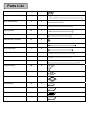
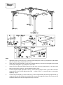
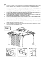
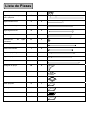
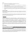
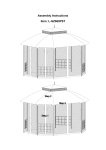
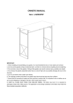
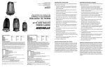
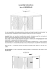
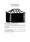
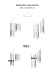
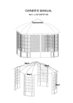
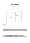
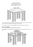
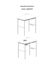
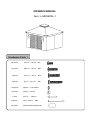
OWNER'S MANUAL
Item: L-GZ224PAL-1
Hardware Pack 1
60 pieces
(AA) 1/4"-20x0.6
Bolt
32 pieces
(BB) 1/4"-20x1.2
Bolt
8 pieces
(CC) 1/4"-20x1.4
Bolt
8 pieces
(II) 1/4"-20x1.75
Bolt
124 pieces
(DD)1/4" Fl at washer
16 pieces
(EE)1/4"-20 Nut
1 piece
16 pieces
96 pieces
(FF)1/4" Wrench
(GG))5/16"x7
Stake
(HH) Mosquito netting hook
Parts List
Top connector
A
1
Long beam with small roof bar
B
4
Short oblique beam
C
4
Long oblique beam
D
4
Top long beam
E
4
Top short beam
F
4
Oblique beam connector
G
4
Long round pole
H
4
Short round pole
I
4
Long support beam
J
4
Short support beam
K
4
Column
L
4
Support triangle
M
8
Column base
N
4
Base cover
O
4
Small canopy
P
1
Big canopy
Q
1
Mosquito netting
R
1
Wall
S
1
Step1
J
K
M
H
M
I
K
H
M
Fig.5
J
M
J
I
Fig.4
Fig.3
K
M
L
K
J
Fig.2
M
M
M
L
L
N(O)
L
N(O)
N(O)
N(O)
Fig.1 Fig.2
L
AA
K
DD
O
AA
K
J
AA
DD N DD
DD
AA
J
J(K)
L
Fig.1
Fig.5
Fig.4
Fig.3
J
K
M
DD BB
L
I
H
DD
AA
Step1
1.
Slide base cover (O) onto column (L), connect column base (N) to column (L) using bolt (AA), flat washer
(DD) and tighten. (Fig.1) Repeat for each column.
2.
Insert side of long sup port beam (J) into sho rt support beam (K ), then conn ect using bolt (A A) and flat
washer (DD) and tighten. (Fig.2) Repeat for each side.
3.
Insert the notch of the short support beam (K) into the notch of the long support beam (J), and then insert
both into the notch of column (L). (Fig.3) Repeat on each corner.
4.
Connect support triangle (M) to the col umn (L), and to the long suppo rt beam (J) as well as the short
support be am (K) usi ng bolt (BB) and flat wash
er (DD) to conne ct. Asse mble all co rners befo re
tightening. (Fig.4)
5.
Connect long round pole (H), short round pole (I), to short support beam (K) and long support beam (J)
using bolt (AA) and flat washer (DD). Assemble all corners before tightening. Note: long round pole (H)
should be attached next to short support beam (K) at one end.
Fig.12
Step2
A
F
E
K
H
M
J
B
I
Fig.6
E
J
K
D
F
H
I
E
Fig.14
F
E
Fig.8
F
J
Fig.13
G
K
M
K
Fig.7
Fig.9
Fig.10
Fig.11
M
C
J
L
N(O)
Fig.8
F
E
EE DD
DD II
Fig.9
E
AA
DD
F
Fig.10
G
F
E
EE DD
CC DD
G
DD EE
C
DD II
Fig.12
A
D
Fig.13
B
AA
D
B
Fig.11
D
B
DD
C
Fig.14
D
EE DD
E
DD CC
Step2
6.
Connect top short beam (F), long support beam (J), top long beam (E) and short support beam (K) using
bolt (AA), flat washer (DD), and assemble all corners before tightening. (Fig.6) Repeat on all sides.
7.
Connect top short be am (F), top lo ng beam (E) and long support beam (J), using bolt (AA) and flat
washer (DD), assemble all corners before tightening. (Fig.7) Repeat on all sides.
8.
Connect one side of the top long bea m (E) to one si de of the top sho rt bea m (F), using bolt (II), fla t
washer (DD) and nut (EE), assemble all corners before tightening. (Fig.8)
9.
Connect the other side of the top long beam (E) to the other side of the top short beam (F), using bolt (II),
flat washer (DD) and nut (EE), assemble all corners before tightening.(Fig.9)
10.
Connect oblique be am co nnector (G) and top short beam (F ), using b olt (AA) and flat wa sher (DD),
assemble all corners before tightening. (Fig.10) Repeat for each beam.
11.
Connect short oblique beam (C) to beam connector (G), using bolt (CC), flat washer (DD) and nut (EE),
assemble all corners before tightening. (Fig.11) Repeat for each beam.
12.
Insert long oblique beam with small roof bar (B) into long pole of top connector (A) and one side of long
oblique beam (D) into short pole of top connector (A). (Fig.12)
13.
Insert one side of long beam with small roof Bar (B) into short oblique beam (C). Then connect using bolt
(AA) and flat washer (DD) and lock tight. (Fig.13)
14.
Connect long oblique b eam (D) to top long be am (E) using bolt (CC), flat wa sher (DD) an d nut (EE),
assemble all corners before tightening. (Fig.14)
P
Step3
Q
Fig.16
Fig.15
Fig. 18
Fig.17
S
R
Fig.19
Fig.17
H(I)
R
(HH)
Fig.18
E(F)
S
(HH)
Fig 19
O
GG
N
Step3
15.
Cover roof with big canopy (Q), do not fully extend. (Fig.15)
16.
Cover top with small canopy (P). (Fig.16)
17.
Hang mosqui to netting (R) onto long ro und pole (H) and sho rt ro und pole (I), usin g mosqui to netting
hooks (HH)). (Fig.17)
18.
Hang wall (S ) onto top l ong be am (E ) and top short beam (F), usin g mo squito netting ho oks (HH).
(Fig.18). Then finish stretching big canopy (Q).
19.
Anchor column base (N) to ground u sing stake (GG), and then cover the colu mn base with base cover.
(Fig.19). Repeat for all columns. Go over all the assembly steps.
Limited Warranty:
This limited warranty is extended to the original purchaser and applies to defects in materials and workmanship
of your item provided the item is maintained with care and used only for personal, residential purposes.
The item is warra nted to be free from
defects in m aterial o r wo rkmanship for a period of
one (1) year. W e
don't reimburse fo r tra nsportation o r delivery costs, or co mpensate the in dividual o r a ny out side party for
assembling or disassembling the product.
Exclusions:
Items used for commercial, contract, or other non-residential purposes, or items damaged due to acts of nature,
vandalism, misu se, or i mproper a ssembly are n ot co vered. Corro sion or rusting of hard
ware is not
covered. Proof of purcha se (dated register receipt) is required for wa rranty claims. W arranty is to the original
purchaser and is non-transferable. Any replacement of warranted items will be in the original style and color, or a
similar style and col or if the origin al is unavailable or ha s been discontinued. As some st ates do not allow
exclusions or limit ations o n an implied warranty , t he above excl usions an d limit ations ma y not apply . This
warranty gives you specific rights, and you may also have other rights, which vary from state to state.
Maintenance:
Our iron/steel components for garden accessories and furniture are coated with rust inhibiting paint that protects
it from ru sting. However, due to th e nature of i ron, surface oxidation (rusting) will occur once these protective
coatings are scratched. This is a natural process and is not a defect! To minimize this condition, we recommend
care when assembling & handling the product to prevent scratching the paint. Should any scratching or damage
occur, we recommend immediate touch-up with rust inhibiting paint. Surface rust can also be easily removed with
a very light application of common cooking oil. If surface oxidation (rusting) occurs and if no measure is taken to
prevent this, the oxidation may st art dripping on to dec k or p atio and cau se d amaging st ains, whi ch ma y be
difficult to remove. This can be prevented if measure is taken to keep the product from oxidizing.
Important: For technical assistance on assembly or replacement parts Please do not return this produ ct to the
store, call Su njoy Industrie s at 1(866 ) 578-6 569 from 8: 30 AM to 5:30 PM EST Monday to Friday or fax the
replacement part form wh ich put into t he p ackage to (74 0)-283-3549 o r Ema il [email protected]
for assistance.
Made in China
MANUAL DEL PROPIETARIO
Articulo No.: L-GZ224PAL-1
Bolsa de Ferretería 1
60 piezas
(AA) 1/4"-20x0.6
Tornillo
32 piezas
(BB) 1/4"-20x1.2
T ornillo
8 piezas
(CC) 1/4"-20x1.4
T ornillo
8 piezas
(II) 1/4"-20x1.75
T ornillo
124 piezas
(DD)1/4" Arandel a Plana
16 piezas
(EE)1/4"-20 Tuerca
1 pieza
16 piezas
96 piezas
(FF)1/4" Llave
(GG))5/16"x7
Estaca
(HH) Anillo para mosquitero
Lista de Piezas
Conexión del techo
A
1
B
4
Viga Inclinada corta
C
4
Viga inclinada larga
D
4
Viga larga del techo
E
4
Viga corta del techo
F
4
G
4
Vara larga redonda
H
4
Vara corta redonda
I
4
Viga de apoyo larga
J
4
Viga de apoyo corta
K
4
Columna
L
4
Triangulo de apoyo
M
8
Base de la columna
N
4
Cubierta de la base
O
4
Toldo pequeño
P
1
Toldo grande
Q
1
Mosquitero
R
1
Pared
S
1
Viga larga con barra p
techo pequeño
Conexión de
inclinadas
las
ara
vigas
Etapa
J
K
M
H
I
M
K
H
M
Fig.5
J
M
Fig.4
J
I
Fig.3
K
M
L
K
J
Fig.2
M
M
M
L
L
N(O)
L
N(O)
N(O)
N(O)
Fig.1 Fig.2
L
Fig.1
AA
K
DD
O
AA
J
AA
DD N DD
DD
AA
J
J (K)
L
K
Fig.5
Fig.4
Fig.3
J
K
M
DD BB
L
I
H
DD
AA
Etapa 1
1.
Deslize la cubierta de la base (O) en la columna (L), conecte la base de la columna (N) a la columna (L)
con tornillo (AA), arandela plana (DD) y apriete. (Fig.1) Reitere para cada columna.
2.
Introduzca la viga de apoyo lateral larga (J) en la viga de apoyo corta (K), y conecte con tornillo (AA) y
arandela plana (DD) y apriete. (Fig.2) Reitere para cada lado.
3.
Introduzca la muesca de la viga de apoyo corta (K) en la muesca de la viga de apoyo larga (J), y luego
introduzca las dos en la muesca de la columna (L). (Fig.3) Reitere en cada esquina.
4.
Conecte el triangulo de apoyo (M) a la columna (L), y a la viga de apoyo larga (J) así como a la viga de
apoyo corta (K) con tornillo (BB) y arandela plana (DD) para fijar. Conecte todas las esquinas antes de
apretar. (Fig.4)
5.
Conecte la vara redonda larga (H), la vara redonda corta (I), a la viga de apoyo corta (K) y a la viga d e
apoyo larga (J) con tornill o (AA) y arand ela plana (DD) . Conecte todas las e squinas antes d e apretar.
Aviso: la vara redonda larga (H) debe conectarse cerca de la viga de apoyo corta (K) en su extremidad.
Fig.12
Etapa 2
A
F
E
K
H
M
J
B
I
D
Fig.6
E
J
K
F
H
Fig.14
F
E
Fig.8
F
J
Fig.13
G
K
Fig.9
Fig.10
Fig.11
M
I
E
C
J
M
K
Fig.7
L
N(O)
Fig.8
F
E
EE DD
DD II
Fig.9
E
AA
DD
F
Fig.10
G
F
E
EE DD
CC DD
G
DD EE
C
DD II
Fig.12
A
D
Fig.13
B
AA
D
Step2
B
Fig.11
D
B
DD
C
Fig.14
D
EE DD
E
DD CC
6.
Conecte la viga del te cho corta (F), la v iga del te cho larga (J), la viga larga del techo (E) y l a viga de
apoyo corta (K) con to rnillo (AA), ara ndela plana (DD), y con ecte todas la s esquinas antes de apretar.
(Fig.6) Reitere en todos los lados.
7.
Conecte la viga del techo cort a (F), la viga del te cho larga (E) y la viga de apoyo larga (J), con tornillo
(AA) y ara ndela plana (DD), cone cte todas la e squinas antes de apretar. (Fig.7) Reitere en todos lo s
lados.
8.
Conecte una extremidad de la viga del t echo larga (E) a una extremidad de la viga del te cho corta (F),
con tornillo (II), arandela plana (DD) y tuerca (EE), conecte todas las equinas antes de apretar. (Fig.8)
9.
Conecte la otra extremidad de la viga del techo larga (E) a la otra extremidad del la viga del techo corta
(F), con tornil lo (II), arand ela plana (DD) y tuerca (EE), conecte todas las esquina s antes de apret ar.
(Fig.9)
10.
Conecte la conexión de las vigas inclinadas (G) y la viga del techo corta (F), con tornillo (AA) y arandela
plana (DD), conecte todas las esquinas antes de apretar. (Fig.10) Reitere para cada viga.
11.
Conecte la viga inclinada corta (C) a la conexión de vigas (G), con tornillo (CC), arandela plana (DD) y
tuerca (EE), conecte todas las esquinas antes de apretar. (Fig.11) Reitere para cada viga.
12.
Introduzca la viga inclinada larga con la barra del techo pequeño (B) en la vara larga de la conexión del
techo (A) y una extremid ad de la viga inclin ada larga (D) en la v ara corta de la conexión del techo (A).
(Fig.12)
13.
Introduzca una extremidad de la viga larga con la barra del techo pequeño (B) en la viga inclinada corta
(C). Conecte con tornillo (AA) y arandela plana (DD) y apriete fuertemente. (Fig.13)
14.
Conecte la viga inclinada larga (D) a la viga larga del techo (E) con tornillo (CC), arandela plana (DD) y
tuerca (EE), conecte todas las esquinas antes de apretar. (Fig.14)
P
Fig.16
Etapa 3
Q
Fig.15
Fig. 18
Fig.17
S
R
Fig.19
Fig.17
H(I)
R
(HH)
Fig.18
E(F)
S
(HH)
Fig 19
O
GG
N
Etapa 3
15.
Cubra el techo con el toldo grande (Q), no lo extienda del todo. (Fig.15)
16.
Cubra el techo con el toldo pequeño (P). (Fig.16)
17.
Cuelgue el mosquitero (R) en la vara redonda larga (H) y la vara redonda corta (I), con los anillos para el
mosquitero (HH)). (Fig.17)
18.
Cuelgue la pared (S) sobre la viga del techo la rga (E) y la viga del tech o co rta (F), con lo s mism os
anillos del mosquitero (HH). (Fig.18). Ahora, podrá terminar de extender el toldo grande (Q).
19.
Ancle la base de la columna (N) a la tierra con las estacas (GG), y deslice las cubiertas de las bases de
las columnas para cubrirlas. (Fig.19 ). Reitere p ara todas l as col umnas. Revise tod as la s etapas de
montaje.
Garantía Limitada:
Esta garantía limitada se extiende al comprador original y se aplica a defectos materiales y de mano de obra de
su a rtículo si empre y cu ando el articula haya sido mantenido co n cui dado y emplea do para u so personal, y
residencial únicamente.
El artículo está garantizado de carecer de defectos materiales o de mano de obra por un periodo de un (1) año.
No reembolsamos por gastos de transporte o de entrega y tampoco compensamos al individuo o cualquier otra
persona por el montaje o desmontaje del producto.
Exclusiones:
Los artículo s empleados p ara uso comercial, bajo contrato, o cualquier otra intención que no se
a
residencial, o los artículos daña dos por intemp eries, vand alismo, abuso, m ontaje i ndebido n o están
cubiertos. La Corr osión o el óxido de la ferretería no están cubiertos. Se precisa una justificació n de
compra (reci bo fechado ) p ara cualqu ier reclamación bajo garantía. La garantía es p ara el comp rador
original y no se puede trasp asar. Cualquier artículo que teng a que ser reemplazado b ajo garantía, será
del estilo y color origina l, o de un estilo o color si milar si el original no está disponible o si ha
sido
descontinuado. Como algunos es tados no permiten exclusiones o
limitaciones sobre una g arantía
implícita, de modo que, las exclusiones y limitaciones mencionadas pueden ser nulas. Esta garantía le da
derechos específicos, y podría usted tener también otros derechos que pueden ser diferentes de un estado
al otro.
Mantenimiento:
Nuestros co mponentes d e ace ro p ara acce sorios y muebles d e jardín está n cubie rtos con una pintu ra que
impide el óxido y lo protege cont ra el óxido. Sin embargo, de bido a la naturale za del h ierro, se oxidara la
superficie de estas capas protectoras si se arañan. ¡Esto es un procedimiento natural y n o un defecto! Para
reducir esta condición, recomendamos cuidado durante el mont aje y la mani pulación del producto para evitar
arañar la pin tura. Si se
ocasiona cu alquier a rañazo o daño, re comendamos retoca r inm ediatamente con
pintura anti- óxido. E l óxido de la superficie puede quitarse fácilmente con una aplicación ligera de aceite para
cocinar. Si se oxida l a superficie, y n o se tom an las medidas adecuadas para evitarlo, el oxido empezara a
gotear sobre su patio o suelo y resultaran manchas, que pueden ser difíciles de eliminar. Esto se puede evitar
si se toman las medidas adecuadas para prevenir el óxido del producto.
Importante: Para asistencia técnica sobre el montaje o las piezas de recambio llame a Sunjoy Industries al
1-(866)-578-6569 de 8h30 a 17h3 0, hora del Este, de lunes a vi ernes o puede mandar el formulario de
pedida de pi ezas de recambio qu e h emos introd ucido en el embalaje p or fax al (7 40) 283- 3549 o por
correo electrónico a [email protected] para más ayuda.
Hecho en China