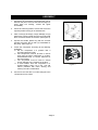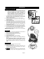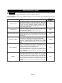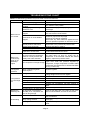
1
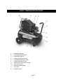
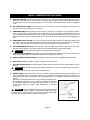
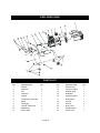
ITEM#AT01204-6
OPERATOR’S
MANUAL
2.5 HP/6-GALLON
AIR COMPRESSOR
IMPORTANT: READ THIS OPERATOR’S MANUAL BEFORE USING
Manufactured in China
©2008 Alton Industries Group, Ltd. – All Rights Reserved
TABLE OF CONTENTS
SAFETY GUIDELINES--------------------------------------------------------------------------------------------3
BASIC COMPRESSOR FEATURES-------------------------------------------------------------------------4
ELECTRIC MOTOR---------------------------------------------------------------------------------------------------5
AIR COMPRESSOR PUMP-----------------------------------------------------------------------------------------5
PRESSURE SWITCH ------------------------------------------------------------------------------------------------5
PRESSURE RELIEF VALVE----------------------------------------------------------------------------------------5
AIR PRESSURE REGULATOR------------------------------------------------------------------------------------5
TANK PRESSURE GAUGE-----------------------------------------------------------------------------------------5
REGULATED PRESSURE GAUGE-------------------------------------------------------------------------------5
AIR LINE OUTLET-----------------------------------------------------------------------------------------------------5
AIR TANK DRAIN VALVE--------------------------------------------------------------------------------------------5
AIR TANK-----------------------------------------------------------------------------------------------------------------5
POWER CORD---------------------------------------------------------------------------------------------------------5
ASSEMBLY-------------------------------------------------------------------------------------------------------------6
OPERATION-----------------------------------------------------------------------------------------------------------7
BREAK-IN OF THE PUMP-------------------------------------------------------------------------------------------7
STARTUP-----------------------------------------------------------------------------------------------------------------7
SHUTDOWN-------------------------------------------------------------------------------------------------------------7
MAINTENANCE CHART------------------------------------------------------------------------------------------8
TROUBLESHOOTING CHART---------------------------------------------------------------------------------9
EXPLODED VIEW & PARTS LIST---------------------------------------------------------------------------10
SPECIFICATION
MODEL NO.----------------------------------AT01204-6
PUMP------------------------------------------OIL LUBRICATED DIRECT DRIVE
MOTOR----------------------------------------2.5 Peak HP
VOLTAGE/AMPS/PHASE-----------------120/13/1
AIR TANK CAPACITY----------------------6 GALLON
CUT-IN PRESSURE-----------------------95 PSI
CUT-OUT PRESSURE-------------------125 PSI
CFM @ 40 PSI------------------------------4.3
CFM @ 90 PSI------------------------------3.5
POWER CORD-----------------------------STW 14 AWG / 72” LENGTH
EXTENSION CORD-----------------------STW 12 AWG / NO LONGER THAN 50 FEET
NOTE: Avoid use of extension cords. If cannot be avoided, the cord should be a minimum
wire size of 12 AWG and no longer than 50 feet.
Use only a 3-wire extension cord that has a 3-blade grounding plug, and a 3-slot
receptacle that will accept the plug on the product.
-Page 2-
SAFETY GUIDELINES
This manual contains information that relates to PROTECTING YOUR SAFETY and PREVENTING EQUIPMENT
PROBLEMS and is very important for you to know and understand. We use the symbols below to help you
recognize this information.
DANGER - POTENTIAL HAZARD THAT WILL RESULT IN SERIOUS INJURY OR LOSS OF LIFE
WARNING - POTENTIAL HAZARD THAT COULD RESULT IN SERIOUS INJURY OR LOSS OF LIFE
CAUTION - POTENTIAL HAZARD THAT MAY RESULT IN MODERATE INJURY OR DAMAGE TO EQUIPMENT
WARNING
1. RISK OF EXPLOSION OR FIRE. Never spray flammable liquids in a confined area. It is normal for
the motor and pressure switch to produce sparks while operating. If sparks come into contact with
vapors from gasoline or other solvents, they may ignite and cause fire or explosion. Do not smoke
while spraying. Do not spray where sparks or flame are present. Keep compressor as far from
spray area as possible. Always operate the compressor in a well-ventilated area.
2. RISK OF ELECTRIC SHOCK. A licensed electrician in accordance with all local and national codes
must install all wirings. To avoid electric shock, NEVER use an electric air compressor outdoors
when it is raining or on a wet surface.
3. RISK OF BURSTING. Rust can weaken the tank.Drain the condensed water from the tank after
each use to reduce rusting. Welding or modifications on the air tank can severely impair tank
strength and cause an extremely hazardous condition. So DO NOT weld, drill or modify the air tank
of this compressor. If a leak is detected in the tank, replace the tank right away.
4. RISK OF INJURY. ALWAYS shut off the compressor, remove the plug from the outlet and bleed all
pressure from the system before servicing the compressor or when the compressor is not in use.
Do NOT use the unit with the shrouds removed. Contact moving parts could cause serious injury.
5. RISK OF BURSTING. Check the maximum pressure rating in the manual or the serial tag label.
Compressor outlet pressure must be regulated so as to never exceed the maximum pressure rating.
Relieve all pressure through the hose before removing or attaching accessories.
6. RISK OF BURSTING. DO NOT adjust the pressure switch or relief valve for any reason. They have
been preset at the factory for the maximum pressure of this unit. If the pressure switch or the relief
valve are tampered with, personal injury or property damage may occur.
7. RISK OF BURNS. Pump and manifold generate high temperature. To avoid burns or other injuries,
DO NOT touch the pump, manifold or transfer tube while the unit is running. Allow the parts to cool
before handling or servicing. Keep children away from the compressor at all times.
8. RISK TO BREATHING. Be certain to read all labels when you are spraying paints or toxic materials,
and follow the safety instructions. Use a respirator mask if there is a chance of inhaling anything
you are spraying. Also, NEVER directly inhale the compressed air produced by a compressor.
9. RISK OF EYE INJURY. ALWAYS wear ANSI Z87.1 approved safety goggles when using an air
compressor. NEVER point any nozzle or sprayer toward a person or any part of the body. If the
spray penetrates the skin, serious injury may occur.
CAUTION
1. Pull the pressure relief valve ring daily to ensure that the valve is functioning properly.
2. The unit must be kept a minimum of 12 inches from the nearest wall, in a well-ventilated area for
cooling.
3. Protect the air hose and electric cord from damage and puncture. Inspect them weekly for weak or
worn spots and replace if necessary.
4. Always wear hearing pretection when using an air compressor. Failure to do so may result in
hearing loss.
5. Operation of the unit should always be in a position that is stable. Never use the unit on a rooftop or
elevated position that could allow the unit to fall or be tipped over.
-Page 3-
BASIC COMPRESSOR FEATURES
A
B
K
C
D
E
F
G
H
J
I
A--------ELECTRIC MOTOR
B--------AIR COMPRESSOR PUMP
C--------PRESSURE SWITCH
D--------PRESSURE RELIEF VALVE
E--------AIR PRESSURE REGULATOR
F--------TANK PRESSURE GAUGE
G--------REGULATED PRESSURE GAUGE
H--------AIR LINE OUTLET
I---------AIR TANK DRAIN VALVE
J---------AIR TANK
K--------POWER CORD
-Page 4-
BASIC COMPRESSOR FEATURES
A. ELECTRIC MOTOR: The motor is used to power the pump. It has a thermal overload protector and an
automatic reset. If the motor overheats for any reason, the thermal overload protector will shut it down
to prevent the motor from being damaged. The motor will automatically restart when it completely
cools.
B. AIR COMPRESSOR PUMP: The pump is used to compress the air and discharge it into the tank via
the piston moving up and down in the cylinder.
C. PRESSURE SWITCH: The switch is used to start or stop the air compressor. It is operated manually.
When in ON position, it allows the motor to start when the air tank pressure is below the factory set
cut-in pressure and allows the motor to stop when the air tank pressure reaches the factory set cut-out
pressure. ALWAYS set this switch to OFF when the unit is not being used, and before unplugging the
unit.
D. PRESSURE RELIEF VALVE: The valve is used to prevent system failures by relieving pressure from
the system when the pressure reaches the preset level while the pressure switch does not shut down
the motor. It will pop open automatically or you can pull the ring on the valve to make it.
E. AIR PRESSURE REGULATOR: The regulator is used to adjust line pressure to the tool you are using.
Turn the knob clockwise to increase pressure and counterclockwise to decrease pressure.
WARNING:Never exceed the maximum working pressure of the tool.
F. TANK PRESSURE GAUGE: The gauge is used to measure the pressure level of the air stored in the
tank. It is not adjustable by the operator, and does not indicate line pressure.
G. REGULATED PRESSURE GAUGE: The gauge is used to measure the regulated outlet pressure.
H. AIR LINE OUTLET: The outlet is used to connect 1/4” NPT air hose.
I.
AIR TANK DRAIN VALVE: The drain valve is used to remove moisture from the air tank after the unit is
shut off.
WARNING:Never attempt to open the drain valve when over 10 PSI of air pressure is in the tank.
J. AIR TANK: The tank is used to store the compressed air.
K. POWER CORD: This product is for use on a nominal 115 volt circuit and should be grounded. A cord
with a grounding plug, as K showed, shall be used. Make sure that the product is connected to an
outlet having the same configuration as the plug (see Figure 1). No adapter should be used with this
product.
Check with a licensed electrician if the grounding instructions are
not completely understood, or if in doubt as to whether the product
Grounded
is properly grounded. Do not modify the plug provided. If it will not
outlet
fit the outlet, have the proper outlet installed by a licensed
electrician.
DANGER: Improper installation of the grounding plug will result
in a risk of electric shock. If repair or replacement of the cord or plug
is necessary, do not connect the grounding wire to either flat blade
terminal. The grounding wire is in green outer surface.
Plug
115V/13 A
Grounding Pin
Figure 1
-Page 5-
ASSEMBLY
1. Unpack the air compressor and inspect the unit for
damage and parts. If the unit has been damaged or
some parts are missing, contact the agent
immediately.
D
2. Check the serial tag label to ensure that it has the
required pressure rating for its intended use.
C
A
3. Take out two(2) wheels(A), two(2) bolts(B), four(4)
washers(C), two(2) nuts(D) from the bag and install
them on the foot section of the tank. (See Figure 2)
4. Unpack the smaller plastic bag with the air filter
included and have the air filter (A) assembled on
the pump. (See Figure 3)
5. Locate the compressor according to the following
guidelines:
a. Set the compressor in a position near a
grounded electrical outlet.
b. The compressor must be at least 12 inches
away from any wall or obstruction, in a clean,
well-ventilated area, to ensure sufficient air
flow and cooling.
c. The compressor must be level to ensure
proper drainage of the moisture in the tank.
d. In cold weather, store the compressor in a
heated building when not in use. This will
reduce problems with motor starting and
freezing of water condensation.
6. Connect an air hose with a 1/4” NPT fitting kit to the
compressor air line outlet.
-Page 6-
B
Figure 2
A
Figure 3
OPERATION
BREAK-IN OF THE PUMP
NOTE: The pump is shipped WITHOUT oil. Before starting, the
break-in oil provided in an oil bottle should be poured
in the pump through the oil nozzle. The break-in oil
should be changed after 8 hours of operation. To
reduce maintenance and repair problems, use only
premium compressor oil. SAE 10W-30 all weather air
compressor oil is recommended for general use.
1. Check the oil level in the pump through the oil sight glass.
The pump oil level must be between A1 and A2. Do not
overfill or underfill. (See A)
2. Turn the pressure switch to the OFF position (See B)
3. Open the tank drain valve (See C). Turn in the counterclockwise direction.
4. Plug in the power cord
5. Turn the pressure switch to the ON position (See D). The
unit will start. Allow the unit to run for half an hour to break
in the internal parts. After about half an hour, if the unit
does not operate properly, shut down immediately and
contact Product Service.
6. After half an hour, turn the pressure switch to the OFF position.
7. Close the tank drain valve. Turn in the clockwise direction.
8. Turn the pressure switch to the ON position. The unit will
start and fill the tank to the cut-out pressure and stop.
NOTE: The pressure switch will restart the motor automatically
as compressed air is used.
OFF
B
ON
D
A
STARTUP
1. Before starting, check the oil sight glass to ensure that oil
level in the pump is at the required level.
2. Turn the pressure switch to the OFF position.
3. Close the tank drain valve.
4. Plug in the power cord.
5. Turn the pressure switch to the ON position.
6. Adjust the pressure regulator to the working pressure of
the tool.
When adjusting from a higher to a lower pressure, turn the
knob counterclockwise past the desired setting, and then
turn clockwise to reach the desired pressure. DO NOT
exceed operating pressure of the tool or accessory being
used.
E
SHUTDOWN
1. Turn the pressure switch to the OFF position.
2. Unplug the power cord.
3. Reduce pressure in the tank through the outlet hose. You
can also pull the relief valve ring and keep it open to relieve
pressure in the tank. (See E)
CAUTION Escaping air and moisture can propel debris that
may cause eye injury. Wear safety goggles when opening
drain valve.
-Page 7-
CLOSE
OPEN
C
MAINTENANCE CHART
WARNING To avoid personal injury, always shut off and unplug the unit and relieve all air pressure
from the system before performing any service on the air compressor.
Regular maintenance will ensure trouble free operation. The items listed in the chart should be inspected
on a regular basis.
ITEM
DESCRIPTION
SERVICE
INTERVAL
Drain the tank
To prevent corrosion of the tank from the inside, the
condensation must be drained at the end of every workday.
Be sure to wear protective goggles. Relieve the air
pressure in the system and open the drain valve on the
bottom of the tank to drain.
Daily
Check the oil
Check the oil level in the pump through the oil sight glass.
The pump oil level must be within the red circle.
Do not overfill or underfill.
Daily
Check the relief valve
Pull the relief valve on the ring daily to ensure that it is
operating properly and to clear the valve of any possible
obstructions.
Daily
Clean the air filter
Test for leakage
Storage
A dirty filter will reduce the unit’s performance and life.
To avoid any contamination inside the pump, the filter
should be cleaned frequently and replaced on a regular
basis. Foam filter should be cleaned in warm and soapy
water.
Check all connections to see if tight. A small leak in any of
the tank, hoses, pipe connections or transfer tubes will
absolutely reduce the unit’s performance.
Spray a small amount of soapy water around the area of
the suspected leak with a spray bottle. If bubbles appear,
repair or replace the faulty component. Do not over tighten
any connections.
Before storing the unit for a long period, use an air blow
gun to clean all dust and debris from the compressor.
Disconnect and coil the power cord up. Clean the filter
element and filter housing. Drain all moisture from the tank.
Pull the pressure relief valve to release all pressure from
the tank. Cover the entire unit to protect it from moisture
and dust.
-Page 8-
Weekly
N/A
N/A
TROUBLESHOOTING CHART
NOTE: Troubleshooting problems may have similar causes and solutions.
PROBLEM
Motor will not
run or start
Motor runs
continuously
when in the
Start/Stop
option
Regulator does
not regulate
pressure
POSSIBLE CAUSE
Power cord not plugged in
Pressure Switch in “OFF”
position
Wrong gauge wire or length of
extension cord
Motor thermal overload switch
tripped
SOLUTION
Plug cord into grounded outlet
Turn switch to “ON” position
Check chart on page 2 for proper gauge wire and
cord length
Turn air compressor off, wait until motor is cool,
then check motor circuit breaker
-Replace fuse or reset circuit breaker
-Check for proper fuse amperage
-Check for low voltage conditions
-Disconnect any other electrical appliances from
circuit or operate compressor on its branch circuit
Fuse blown or circuit breaker
tripped
Air tank pressure exceeds
preset pressure switch limit
Check valve stuck open
Loose electrical connections
Possible defective motor,
capacitor or check valve
Pressure switch does not shut
off motor when air compressor
reaches cut-out pressure and
safety relief valve activates
Dirty or damage regulator
internal parts.
Replace regulator.
Tank drain valve is open
Restricted air intake
Prolonged excessive use of air
Hole in air hose
Tank leaks
Moisture in
discharge air
Valve leaks
Condensation in air tank caused
by high level of atmospheric
humidity or air compressor did
not run long enough.
Poor ventilation
Overheating
Contact authorized service center
Move the pressure switch to the OFF position. If
the motor does not shut off, unplug the air
compressor. If the electrical contacts are welded
together, replace the pressure switch.
Check air requirement of accessory used. If it is
higher than CFM and pressure supplied by
Air compressor not large enough
compressor, a larger compressor is needed. Most
accessories are rated at 25% of actual CFM while
running continuously.
Fittings leak
Low pressure
or not enough
air
Motor will start automatically when tank pressure
drops below cut-in pressure of pressure tank.
Remove and clean or replace
Contact authorized service center
Dirty cooling surfaces
Leaking valve
Check fittings with soapy water. Tighten or reseal
leaking fittings. But do not over tighten.
Close drain valve
Clean or replace air filter element.
Decrease amount of air used
Check and replace if necessary
Replace unit immediately. DO NOT attempt to
repair.
Check and replace worn parts.
Drain air tank after each use. Drain air tank more
often in humid weather and use an air line filter.
Relocate compressor to an area with cool, dry and
well-circulated air.
Clean all cooling surfaces of pump and motor
thoroughly.
Replace worn parts and reassemble with new
seals.
-Page 9-
EXPLODED VIEW
PARTS LIST
P/N
DESCRIPTION
QTY
P/N
DESCRIPTION
QTY
1
Shroud
1
12
Handle cover
1
2
Wheel kit
2
13
Pressure Switch
1
3
Fan
1
14
Adapter fitting
1
4
Capacitor
1
15
Regulator
1
5
Air filter
1
16
Pressure gauge
2
6
Pump/motor assembly
1
17
Relief valve
1
7
Elbow
1
18
Air tank
1
8
Oil fill plug
1
19
Pad kit
2
9
Transfer tube w/fins
1
20
Drain valve
1
10
Bleeder tub
1
21
Oil sight glass
1
11
Check valve
1
22
Power cord
1
-Page 10-