1
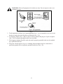
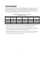
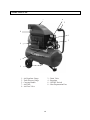
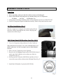
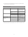
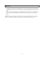
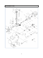
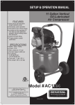
 AIR COMPRESSOR IDENTIFICATION
For information and questions contact customer service at 1-800-232-1195. Please fill out the
information below and have it accessible prior to calling. For the Serial Number refer to the
specifications sticker on your Air Compressor.
DATE OF PURCHASE: _______________________________________________________
PURCHASED FROM: ________________________________________________________
ITEM #:
_______________________________________________________________
SERIAL NUMBER: _________________________________________________________
2 TABLE OF CONTENTS
Specifications …………………………………………………………………………..
Important Safety Instructions...…………………………………………………………
General Safety Instructions……………………………………………………………..
Air Compressor Safety Information …………………………………………………...
Electrical Instructions…………………………………………………………………..
Components…………………………………………………………………………….
Assembly Instructions………………………………………………………………….
Operation………………………………………………………………………………
Maintenance…………………………………………………………………………….
Troubleshooting…………………………………………………………………………
Service…………………………………………………………………………………..
Exploded View………………………………………………………………………….
Parts List………………………………………………………………………………...
Warranty…………………………………………………………………………………
SPECIFICATIONS
6 Gallon Horizontal Tank Air Compressor
Item #:
Motor:
Pressure Range:
Air Flow:
Air Outlet Size:
Tank Capacity:
Weight:
22060
120V, 60Hz, 13 Amps
85–125 psi
4.2 CFM @ 40 psi
3.2 CFM @ 90 psi
1/4" NPT
6 Gallons
50 lbs.
3 3
4
4-6
6-7
7-9
10
11
12-13
13-15
15
16
17
18
19
IMPORTANT SAFETY INSTRUCTIONS
1. The purpose of safety symbols is to attract your attention to possible dangers. The safety
symbols, and the explanations with them, deserve your careful attention and understanding.
The safety warnings do not by themselves eliminate any danger. The instructions or warnings
they give are not substitutes for proper accident prevention measures.
WARNING: This is the safety alert symbol. It is used to alert you to potential personal
injury hazards. Obey all safety messages that follow this symbol to avoid possible
injury or death.
Note: Advises you of information or instructions vital to the operation or maintenance of the
equipment.
2. Servicing requires extreme care and knowledge and should be performed only by a qualified
service technician. For service we suggest you return the tool/equipment to Power Pro for
repair. When servicing, use only identical Power Pro replacement parts.
3. READ ALL INSTRUCTIONS BEFORE USING YOUR AIR COMPRESSOR.
4. Failure to follow all instructions listed below may result in electrical shock, fire and/or
serious personal injury.
WARNING: Do not attempt to operate this tool/equipment until you have read
thoroughly and understand completely all instructions, safety rules, contained in this
manual. Failure to comply can result in accidents involving fire, electric shock, or
serious personal injury. Save this Operator's Manual and review frequently for continuing safe
operation and instructing others who may use this tool/equipment.
5. Safe operation of this tool/equipment requires that you read and understand this Operator's
Manual and all labels affixed to the tool/equipment. Safety is a combination of common
sense, staying alert and knowing how your tool/equipment works.
GENERAL SAFETY INSTRUCTIONS
WARNING: Read all safety warnings and instructions. Failure to follow the warnings and
instructions may result in electric shock, fire and/or serious injury.
SAVE ALL WARNINGS AND INSTRUCTIONS FOR FUTURE REFERENCE.
4 Work Area Safety
1. Keep work area clean and well lit. Cluttered or dark areas invite accidents.
2. Do not operate your Air Compressor in explosive atmospheres, such as in the presence of
flammable liquids, gases or dust. Air Compressor motors produce sparks which may ignite
the dust or fumes.
3. Keep children and bystanders away from an operating Air Compressor.
Electrical Safety
1. Air Compressor plugs must match the outlet. Never modify the plug in any way. Do not use
any adapter plugs with grounded Air Compressors. Standard plugs and matching outlets will
reduce the risk of electric shock.
2. Do not expose your Air Compressor to rain or wet conditions. Water entering your Air
Compressor will increase the risk of electric shock.
3. Do not abuse the cord. Never use the cord for unplugging your Air Compressor. Keep the
cord away from heat, oil, sharp edges or moving parts. Damaged or entangled cords increase
the risk of electric shock.
Personal Safety
1. Stay alert, watch what you are doing and use common sense when operating your Air
Compressor. Do not use your Air Compressor while you are tired or under the influence of
drugs, alcohol or medication. A moment of inattentiveness while operating your Air
Compressor may result in serious personal injury.
2. Use protective safety equipment. Always wear ANSI-approved eye protection during setup
and use.
3. Prevent unintentional starting. Ensure the switch is in the OFF position before connecting to
power source or moving your Air Compressor.
Air Compressor Use and Care
1. Do not use your Air Compressor if the switch does not turn ON and OFF. An Air
Compressor that cannot be controlled with the switch is dangerous and must be repaired.
2. Disconnect the plug from the power source before making any adjustments, changing
accessories, or storing your Air Compressor. This preventive safety measure reduces the risk
of starting your Air Compressor accidentally.
3. Store your Air Compressor out of the reach of children and do not allow people unfamiliar
with your Air Compressor or these instructions to operate it. An Air Compressor is
dangerous in the hands of untrained users.
5 4. Maintain your Air Compressor. Keep your Air Compressor clean for maximum performance.
Follow the instructions for lubricating and changing accessories. Keep your Air Compressor
dry, clean and free from oil and grease. Check for misalignment or binding of moving parts,
breakage of parts and any other condition that may affect your Air Compressor's operation. If
damaged, have your Air Compressor repaired professionally before use. Many accidents are
caused by a poorly maintained Air Compressor.
5. Use your Air Compressor in accordance with these instructions, taking into account the
working conditions and the work to be performed. Use of your Air Compressor for
operations different from those intended could result in a hazardous situation.
Service
Have your Air Compressor serviced by a qualified professional repair person using only identical
replacement parts. This will ensure that the safety of your Air Compressor is maintained.
AIR COMPRESSOR SAFETY INFORMATION
1. RISK OF FIRE OR EXPLOSION – Do not spray flammable liquid in a confined area or
towards a hot surface. The spray area must be well-ventilated. Do not smoke while spraying
or spray where spark or flame is present.
2. ARCING PARTS – Keep your Air Compressor at least 20 feet away from explosive vapors,
such as when spraying with a spray gun.
3. RISK OF BURSTING – Do not adjust regulator higher than marked maximum pressure of
attached pneumatic tool/equipment.
4. RISK OF INJURY – Do not direct air stream at people or animals.
5. Do not use to supply breathing air.
6. Do not leave your Air Compressor unattended for an extended period while plugged in.
Unplug your Air Compressor after use.
7. Keep your Air Compressor well-ventilated and do not cover during use.
8. Drain tank daily or after use. Internal rust causes tank failure and explosion.
9. Your Air Compressor's cylinder head and air lines get hot during operation. Do not touch or
allow children nearby during or immediately following operation.
10. Do not use the air hose to move your Air Compressor.
11. Release the pressure in the storage tank before moving.
12. The use of accessories or attachments not recommended by the manufacturer may result in
bodily injury.
13. All air line components, including hoses, pipe, connectors, and filters must be rated for a
minimum working pressure of 150% of the maximum system pressure.
14. Industrial applications must follow OSHA guidelines.
6 15. This product is not a toy. Keep it out of reach from children.
16. People with pacemakers should consult their physician(s) before use. Electromagnetic fields
in close proximity to heart pacemaker could cause pacemaker interference or pacemaker
failure.
WARNING: The brass components of this product contain lead, a chemical known to
the State of California to cause birth defects (or other reproductive harm). (California
Health & Safety code 25249.5, et seq.)
17. The warnings, precautions, and instructions discussed in this Operator's Manual cannot cover
all possible conditions and situations that may occur. It must be understood by the operator
that common sense and caution are factors which cannot be built into this product, but must
be supplied by the operator.
ELECTRIC INSTRUCTIONS
Grounding Instructions
1. IN THE EVENT OF A MALFUNCTION OR BREAKDOWN, grounding provides the path
of least resistance for electric current and reduces the risk of electric shock. This
tool/equipment is equipped with an electric cord that has an equipment grounding conductor
and a grounding plug. The plug MUST be plugged into a matching outlet that is properly
installed and grounded in accordance with ALL local codes and ordinances.
2. DO NOT MODIFY THE PLUG PROVIDED. If it will not fit the outlet, have the proper
outlet installed by an electrician.
3. IMPROPER CONNECTION of the equipment grounding conductor can result in electric
shock. The conductor with the green insulation (with or without yellow stripes) is the
equipment grounding conductor. If repair or replacement of the electric cord or plug is
necessary, DO NOT connect the equipment grounding conductor to a live terminal. CHECK
with a licensed electrician or service personnel if you do not completely understand the
grounding instructions, or if you are not sure if the tool/equipment is properly grounded.
4. USE ONLY THREE WIRE EXTENSION CORDS with have 3-prong plugs and 3-prong
outlets that accept the tool/equipment’s plug. Repair or replace damaged or worn cords
immediately.
5. CAUTION: In all cases, make certain the outlet is properly grounded. If you are not sure if it
is, have a licensed electrician check the outlet.
7 WARNING: This tool/equipment is for indoor use only. Do not expose to rain or use
in damp locations.
1.
2.
3.
4.
Fig. 1
Tools/equipment with three wire grounding plugs (Fig. 1, A) are intended for use on a circuit
that has an outlet that looks like the one illustrated (Fig. 1, B).
A temporary adapter (Fig. 1, B & C) may be used to connect this plug to a 2-pole receptacle
(Fig. 1, B) if a properly grounded outlet is not available.
The temporary adapter should be used only until a properly grounded outlet can be installed
by a qualified electrician.
The green colored rigid ear, lug, etc. extending from the adapter must be connected to a
permanent ground such as a properly grounded outlet box (Fig. 1, D).
8 Extension Cord Guidelines
Make sure your extension cord is in good condition. When using an extension cord, be sure to
use one heavy enough to carry the current your product will draw. An undersized cord will cause
a drop in line voltage resulting in loss of power and overheating. The table below shows the
correct size to be used according to cord length and nameplate ampere rating. If in doubt, use the
next heavier gauge. The smaller the gauge number, the heavier the cord.
Minimum Gauge for Extension Cords (AWG)
(When using 120 V only)
Ampere Rating
Total Length of Cord in feet
More Than
Not More
25
50
100
150
Than
0
6
18
16
16
14
6
10
18
16
14
12
10
12
16
16
14
12
12
16
14
12
Not Recommended
1. Be sure your extension cord is properly wired and in good condition. Always replace a
damaged extension cord or have it repaired by a qualified person before using it.
2. Protect your extension cords from sharp objects, excessive heat and damp or wet areas.
3. Use a separate electrical circuit for your tools/equipment. This circuit must not be less than a
#12 wire and should be protected with a 20 Amp time-delayed fuse.
4. Before connecting the motor to the power line, make sure the switch is in the OFF position
and the electric current is rated the same as the current stamped on the motor nameplate.
Running at a lower voltage will damage the motor.
9 COMPONENTS
7
6
5
8
4
3
9
1
2
1 – Air Regulator Gauge
3 – Tank Pressure Gauge
5 – Carrying Handle
7 – Air Filter
9 – Air Flow Valve
2 – Drain Valve
4 – Regulator
6 – ON/OFF Switch
8 – Heat Dispensation Fins
10 ASSEMBLY INSTRUCTIONS
Unpacking
1. When unpacking, make sure that the machine is intact and undamaged.
2. Please check that the following items are included with your Air Compressor.
– Oil Bottle – Air Filter – Oil Breather Cap
3. If any parts are missing or broken, please call our customer services at 1-800-232-1195.
4. Your Air Compressor requires minimum assembly. Remove the parts from the carton.
Air Filter Installation (Fig. 3)
This Air Compressor is shipped with a plastic plug in the air
filter hole. Before operating this unit, remove the plug and
connect the air filter (Fig 3).
Fig.3
Add Oil and Install Oil Breather Cap (Fig. 4 & 5)
1. Your Air Compressor ships without oil in the Crankcase.
Note: BEFORE STARTING YOU AIR COMPRESSOR YOU
MUST ADD OIL TO THE CRANKCASE AS DESCRIBED
BELOW.
2. Place your Air Compressor on level ground.
3. Remove the Oil Shipping Plug from the Oil Fill Hole located
on the top of the Crankcase cover at the rear of the Air
Compressor (Fig. 4).
4. Slowly pour the oil into the Oil Fill Hole until the oil level
rises to the center of the red dot on the Oil Sight Glass (Fig. 5).
Fig. 4
5. Install the Oil Breather Cap into the Oil Fill Hole.
Fig. 5
11 OPERATION
BEFORE OPERATING YOUR NEW AIR COMPRESSOR complete the following steps.
1. Check that all nuts and bolts are secure.
2. Make sure the oil has been properly added to your Air Compressor.
3. Place your Air Compressor on a firm, level surface in a clean, dry, well ventilated area.
4. Your Air Compressor should be located 12 to 18 inches from walls or any other obstruction
which would interfere with airflow. Your Air Compressor should be located in a temperature
controlled area between 32°F and 95°F.
5. Do not place rags, containers or other material on top of your Air Compressor.
Power Source Connection
Your Air Compressor is designed to operate on a properly grounded 120 volt, 60HZ, single
phase, alternating current (AC) power source with a fused 20 Amp time delayed fuse or circuit
breaker. It is recommended that a qualified electrician verify the ACTUAL VOLTAGE at the
receptacle into which the unit will be plugged and confirm that the receptacle is properly fused
and grounded. The use of the proper circuit size can eliminate nuisance circuit breaker tripping
while operating your Air Compressor. For electrical details see pages 7–9.
Initial Start-Up Procedures
1. Open the Air Tank Drain Valve to permit air to escape, preventing air pressure buildup in the
Air Tank.
2. Run the compressor for a minimum of 20 minutes in this “no-load” position to lubricate the
piston.
3. Close Air Tank Drain Valve. Your compressor is ready for use.
4. See pneumatic tool/equipment instructions for instructions on how to connect the
tool/equipment to your Air Compressor.
Depending on the CFM draw of the tool/equipment being operated, your new Air Compressor
can be used for operating paint sprayers, air tools/equipment, grease guns, airbrushes, caulking
guns, abrasive blasters, tire & plastic toy inflation, spraying weed killer and insecticides, etc.
Proper adjustment of the Air Pressure Regulator is necessary for all of these operations. Refer to
the air pressure specifications provided with the tool/equipment you are using.
12 General Overview
1. To compress air, the piston moves up and down in the cylinder. On the down stroke air is
drawn in through the valve inlet. The discharge valve remains closed. On the upstroke of the
piston air is compressed.
2. The inlet valve closes and air is forced out through the discharge valve, through the Check
Valve, and into the Air Tank.
3. Working air is not available until the compressor has raised the tank pressure above that
required at the air service connection.
4. The air inlet filter openings must be kept clear of obstructions, which could reduce air
delivery of the compressor.
Air Pressure Adjustment
1. Your Air Compressor is supplied with an Air Pressure Regulator. This Regulator adjusts the
air pressure.
2. To increase air pressure, turn the Air Regulator clockwise.
3. To decrease air pressure, turn the Air Regulator counterclockwise.
4. The Air Regulator gauge will show the current pressure selected.
MAINTENANCE
Daily (or before each use)
1. Check oil level.
2. Check for any unusual noise or vibration.
3. Be sure all nuts and bolts are tight.
Weekly
1. Clean breather hole on Oil Breather Cap.
2. Drain water from the Air Tank through the Drain Valve.
3. Keep Air Filter clean at all times. Do not operate your Air Compressor with the air filter
removed.
4. A dirty Air Filter will not allow your Air Compressor to operate at full capacity. Before you
use your Air Compressor, check the Air Filter to be sure it is clean. If it is dirty replace the
filter element.
13 Monthly
Inspect the air system for leaks by applying soapy water to all joints. Tighten these joints if leaks
are discovered.
6 Months (or after 250 hours of operation - whichever comes first)
Change Air Compressor Oil.
Note: Change the oil more often if your Air Compressor is used near paint spraying operations
or in dusty environments.
Checking the Air Compressor Oil
1. Place your Air Compressor on a level surface. The oil level should be at the red dot on the
Oil Sight Glass.
2. If oil level is low, remove Oil Breather Cap and add enough oil to bring the oil level to the
red dot on the Oil Sight Glass.
Changing the Air Compressor Oil
Note: This compressor uses only SAE 5W-30 motor oil.
1. Remove the Oil Sight Glass by turning counterclockwise with wrench.
Note: Oil will begin to drain as the Oil Sight Glass is loosened. Make sure a funnel and oil pan
are in place BEFORE loosening the Oil Sight Glass.
2. Once the Oil Sight Glass is removed, tilt your Air Compressor forwards to allow all the oil to
drain out of the Crankcase.
3. Once the oil is drained, replace the Oil Sight Glass and securely tighten in place with a
wrench. Be careful not to over tighten the Oil Sight Glass, as this could damage the rubber
seal.
4. Place your Air Compressor on level surface.
5. Remove the Oil Breather Cap.
6. Slowly pour the oil into the oil fill hole, until the oil level rises to the center of the red dot on
the Oil Sight Glass.
7. Install the Oil Breather Cap into the oil fill hole.
8. Always inspect Air Compressor before use, and make sure it is in good working condition.
Use compressed air to clean the machine where possible.
9. Check the power cable to make sure it is intact and free from cracks, bare wires etc.
14 10. Avoid using solvents when cleaning plastic parts, most plastics are susceptible to damage
from the various types of commercial solvents.
TROUBLESHOOTING
Problem
Air compressor will not start.
Low pressure
Safety valve releasing.
Oil discharge in air
compressor.
Cause
Thermal overload.
Blown fuse or circuit breaker
tripped.
Loose electrical connections.
Restricted air filter.
Defective check valve.
Air leak in safety valve.
Defective pressure switch.
Too much oil in crankcase.
Air compressor overheated.
Restricted oil breather cap.
Solution
Allow to cool and push the
reset button located in the
crankcase close to the air
filter.
Replace or reset fuse/circuit
breaker.
Check wiring connections.
Replace air filter.
Replace check valve.
Check valve by pulling on
ring. If condition persists,
replace valve.
Replace pressure switch.
Drain crankcase and refill to
proper level on oil sight glass.
Reduce air pressure
regulation.
Clean or replace oil breather
cap.
If trouble persists please call our customer service 1-800-232-1195, M-F 8-5 CST.
15 SERVICE
1. Mechanical and/or electrical tool/equipment service is to be performed only by professional
qualified repair personnel. Service performed by unqualified personnel may result in a risk of
injury.
2. When servicing a tool/equipment, use only identical replacement parts. Use of unauthorized
parts or failure to follow maintenance instructions may create a risk of electrical shock or
injury.
NOTE: If any parts are damaged or missing, do not attempt to plug in the power cord and turn
the switch on until the damaged or missing parts are obtained and are installed correctly.
16 EXPLODED VIEW
17 PARTS LIST
Part #
1
2
3
4
5
6
7
8
9
10
11
12
13
14
15
16
17
18
19
20
21
22
23
24
25
26
27
28
29
30
31
32
33
34
35
36
Stock #
22040-001
22040-002
22040-003
22040-004
22040-005
22040-006
22040-007
22040-008
22040-009
22040-010
22040-011
22040-012
22040-013
22040-014
22040-015
22040-016
22040-017
22040-018
22040-019
22040-020
22040-021
22040-022
22040-023
22040-024
22040-025
22040-026
22040-027
22040-028
22040-029
22040-030
22040-031
22040-032
22040-033
22040-034
22040-035
22040-036
Description
Crankcase
Crank Shaft
Gasket
Crankcase Cover
Bolt
O-ring
Oil Sight Glass
Bolt
Washer
Oil Breather Cap
Bolt
Connecting Rod
Circle Clip
Piston Pin
Piston
Piston Oil Ring
Piston Ring
Gasket
Cylinder
Washer
Bolt
Valve Gasket
Valve
Valve Plate
Gasket
Head Gasket
Elbow Connector
Cylinder Head
Washer
Bolt
Air Filter
Capacitor
Washer
Bolt
Motor Cover
Bolt
Part #
37
38
39
40
41
42
43
44
45
46
47
48
49
50
51
52
53
54
55
56
57
58
59
60
61
62
63
64
65
66
67
68
69
70
71
72
18 Stock #
22040-038
22040-039
22040-040
22040-041
22040-042
22040-043
22040-044
22060-044
22060-045
22060-046
22060-047
22060-048
22060-049
22040-050
22060-051
22060-052
22060-053
22060-054
22060-055
22060-056
22040-049
22060-058
22040-064
22060-060
22040-062
22060-062
22040-061
22060-064
22060-065
22060-066
22040-057
22060-068
22060-069
22060-070
22060-071
22040-069
Description
Fan
Motor Back Cover
Stator
Bearing
Rotor
Bearing
Oil Sealing
Air Tank
Nut
Washer
Wheel
Washer
Bolt
Drain Valve
Bolt
Washer
Rubber Foot
Washer
Bolt
Handle Grip
Safety Valve
Pressure Switch
Tank Pressure Gauge
Connector
Regulator
Air Flow Valve
Air Regulator Gauge
Unloading Nut
Uploading Pipe
Exhaust
Check Valve
Exhaust Nut
Exhaust Pipe
Power Cord
Wire Cable
Overload Reset
ONE (1) YEAR LIMITED WARRANTY
Remember to save your receipt and to accurately fill out and mail your product
registration card. You must provide proof of purchase for all warranty work.
POWER PRO products are warranted to be free from defects in materials and workmanship
for a period of one (1) year from date of original purchase. Products used for Commercial or
Rental use have a warranty period of 90 days from date of original purchase. Keep purchase
receipt and mail in the product registration card for proof of purchase.
POWER PRO will repair or replace, at its discretion, any part that is proven to be defective in
materials or workmanship under normal use during the one (1) year warranty period.
Warranty repairs or replacements will be made without charge for parts or labor. Parts
replaced during warranty repairs will be considered as part of the original product and will
have the same warranty period as the original product.
To exercise the warranty, DO NOT RETURN TO RETAILER. Instead, call the toll free
Customer Service number: (800) 232-1195 and you will be instructed on where to take the
products for warranty service. Take the products and proof of purchase (your receipt) to the
repair facility recommended by the Customer Service Representative.
All transportation costs under warranty, including return to the factory if necessary, are to be
borne by the purchaser and prepaid by the purchaser. The term “purchaser” means the person
for whom the product is originally purchased. This warranty is non-transferable.
The warranty does not extend to products damaged or affected by fuel contamination,
accidents, neglect, misuse, unauthorized alterations, use in an application for which the
product was not designed and any other modifications or abuse.
POWER PRO is not liable for any indirect, incidental or consequential damages from the sale
or use of this product. Any implied warranties are limited to one (1) year as stated in this
written limited warranty. Some states do not allow the exclusion or limitation of incidental or
consequential damages. Some states do not allow limitation on the length of an implied
warranty. This warranty gives you specific legal rights, and you may have other rights that
vary from state to state.
19 20