1
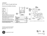
KGS 80 MITER SAW
Manual
Fig. 1
8
12
3
7
9
10
11
15
13
0
15
2
30
4
5
1
6
Fig. 2a
8
12
10
3
7
9
13
15
0
15
11
30
5
6
2
4
1
Fig. 2b
-2-
8
12
7
4
0
1
15
30
9
15
0
5
15
10
30
6
2
3
Fig. 3
Fig. 4
2
1
30
30
3
15
0
15
-3-
Fig. 5b
15
0
15
Fig. 5a
5
4
30
1
Operating instructions
KGS 80 Miter Saw
Contents:
1
2
3
4
5
6
7
8
8.1
8.2
8.2.1
8.2.2
8.2.2.1
8.2.2.2
8.2.3
9
10
10.1
10.2
General safety notes . . . . . . . . . . . . . . . . . . . . . . . . . . . . . . . . . . 4
Addditional safety instructions for Miter Saws. . . . . . . . . . . . . . . . . . . . . 6
Grounding instructions . . . . . . . . . . . . . . . . . . . . . . . . . . . . . . . . . 6
General view (fig. 1) . . . . . . . . . . . . . . . . . . . . . . . . . . . . . . . . . . 7
Description of machine. . . . . . . . . . . . . . . . . . . . . . . . . . . . . . . . . 7
Technical data . . . . . . . . . . . . . . . . . . . . . . . . . . . . . . . . . . . . . 8
Before beginning work . . . . . . . . . . . . . . . . . . . . . . . . . . . . . . . . . 8
Working with the KGS 80 Miter Saw . . . . . . . . . . . . . . . . . . . . . . . . . . 8
Cutting capacity . . . . . . . . . . . . . . . . . . . . . . . . . . . . . . . . . . . . 8
Sawing . . . . . . . . . . . . . . . . . . . . . . . . . . . . . . . . . . . . . . . . . 9
General notes on setting the saw head . . . . . . . . . . . . . . . . . . . . . . . . 9
Straight and mitre cuts . . . . . . . . . . . . . . . . . . . . . . . . . . . . . . . . . 9
If you would like to produce straight cuts (see fig. 2a). . . . . . . . . . . . . . . . . 9
If you would like to produce mitre cuts: (See fig. 2b): . . . . . . . . . . . . . . . . 10
Working with the Length Stop (see fig. 4). . . . . . . . . . . . . . . . . . . . . . . 10
Accessories . . . . . . . . . . . . . . . . . . . . . . . . . . . . . . . . . . . . . . 10
Care and Maintenance . . . . . . . . . . . . . . . . . . . . . . . . . . . . . . . . 11
Replacing the saw blade (see fig. 5a and 5b): . . . . . . . . . . . . . . . . . . . . 11
Cleaning. . . . . . . . . . . . . . . . . . . . . . . . . . . . . . . . . . . . . . . . 11
Dear Customer!
Using these instructions
• makes it easier to get familiar with the
device
• prevents malfunctions caused by improper
handling, and
• lengthens the service life of your device.
Please keep these instructions readily accessible at all times.
Use the device only when you have understood it exactly and always adhere to the
instructions.
PROXXON is not liable for the safe functioning
of the device in cases of:
• handling that does not conform to the usual
usage,
• purposes of use not designated in the
instructions,
• disregard of the safety instructions.
-4-
You are not entitled to guarantee claims in
cases of:
• operator errors,
• inadequate maintenance.
For your own safety, please follow the safety
instructions exactly.
Use only genuine PROXXON replacement
parts.
We reserve the right to make improvements in
the sense of technical progress. We wish you
much success with the device.
1 General safety notes
KNOW YOUR POWER TOOL!
Read and understand instruction manual!
Understand your power tool´s application, limitations, and potential hazards.
Warning!
Failure to read all instructions and follow the
general safety warnings and other safety
warnings and cautions may result in serious
personal injury.
12.
1. KEEP GUARDS IN PLACE and in working
order.
2. REMOVE ADJUSTING KEYS AND
WRENCHES. Form habit of checking to
see that keys and adjusting wrenches are
removed from tool before turning it on.
3. KEEP WORK AREA CLEAN. Cluttered
areas and benches invite accidents.
4. DON’T USE IN DANGEROUS ENVIRONMENT. Don’t use power tools in damp or
wet locations, or expose them to rain.
Keep work area well lighted.
5. KEEP CHILDREN AWAY. All visitors should
be kept safe distance from work area.
6. MAKE WORKSHOP KID PROOF with padlocks, master switches, or by removing
starter keys.
7. DON’T FORCE TOOL. It will do the job
better and safer at the rate for which it
was designed.
8. USE RIGHT TOOL. Don’t force tool or
attachment to do a job for which it was
not designed.
9. USE PROPER EXTENSION CORD. Make
sure your extension cord is in good condition. When using an extension cord, be
sure to use one heavy enough to carry the
current your product will draw. An undersized cord will cause a drop in line voltage
resulting in loss of power and overheating.
Table 1 shows the correct size to use
depending on cord length and nameplate
ampere rating. If in doubt, use the next
heavier gage. The smaller the gage number, the heavier the cord.
Exception No. 1:
The reference to the table and the table
itself may be omitted if a statement indicating the appropriate gage and length is
incorporated into the instruction.
Exception No. 2:
The information regarding extension cords
need not be provided for a permanently
connected tool.
10. WEAR PROPER APPAREL. Do not wear
loose clothing, gloves, neckties, rings,
bracelets, or other jewelry which may get
caught in moving parts. Nonslip footwear
is recommended. Wear protective hair
covering to contain long hair.
Exception: The reference to gloves may be
omitted from the instructions for a grinder.
11. ALWAYS USE SAFETY GLASSES. Also
use face or dust mask if cutting operation
13.
14.
15.
16.
17.
18.
19.
20.
21.
is dusty. Everyday eyeglasses only have
impact resistant lenses, they are NOT
safety glasses.
SECURE WORK. Use clamps or a vise to
hold work when practical. It’s safer than
using your hand and it frees both hands to
operate tool.
DON’T OVERREACH. Keep proper footing
and balance at all times.
MAINTAIN TOOLS WITH CARE. Keep
tools sharp and clean for best and safest
performance. Follow instructions for lubricating and changing accessories.
DISCONNECT TOOLS before servicing;
when changing accessories, such as
blades, bits, cutters, and the like.
REDUCE THE RISK OF UNINTENTIONAL
STARTING. Make sure switch is in off
position before plugging in.
USE RECOMMENDED ACCESSORIES.
Consult the owner’s manual for recommended accessories. The use of improper
accessories may cause risk of injury to
persons.
NEVER STAND ON TOOL. Serious injury
could occur if the tool is tipped or if the
cutting tool is unintentionally contacted.
CHECK DAMAGED PARTS. Before further
use of the tool, a guard or other part that
is damaged should be carefully checked
to determine that it will operate properly
and perform its intended function – check
for alignment of moving parts, binding of
moving parts, breakage of parts, mounting, and any other conditions that may
affect its operation.
A guard or other part that is damaged
should be properly repaired or replaced.
DIRECTION OF FEED. Feed work into a
blade or cutter against the direction of
rotation of the blade or cutter only.
NEVER LEAVE TOOL RUNNING UNATTENDED. TURN POWER OFF. Don’t leave
tool until it comes to a complete stop.
Table 1:
Minimum gage for cord:
Total length of
cord in feet
25 ft
50 ft
100 ft 150 ft
AWG:
18
16
16
14
-5-
2 Addditional safety instructions for
Miter Saws
j)
a) Wear eye protection.
Projectiles thrown away from the machine
could cause serious permanent eye damage. Always wear safety goggles, not
glasses, complying with ANSI Z87.1 (or in
Canada CSA Z94-3-M88). Everyday eyeglasses have only impact resistant lenses.
They are not safety glasses! Safety goggles are available at many local retail
stores. Glasses or goggles not in compliance with ANSI or CSA could seriously
hurt you when they break.
b) Keep hands out of path of saw blade.
Avoid contact with any coasting blade. It
can still cause severe injury.
c) Do not operate saw without guards in
place.
Check blade guard for proper closing
before each use. Do not operate saw if
blade guard does not move freely and
close instantly. Never clamp or tie the
blade guard into the open position.
d) Do not perform any operation freehand.
The workpiece must be secured firmly
against the turn base and guide fence with
a vise during all operations. Never use
your hand to secure the workpiece.
Always use vise!
Check damaged parts and watch the
saw while it runs
Before use of the tool, any part that is
damaged should be carefully checked to
ensure that it will operate properly and
perform its intended function. If the saw
makes an unfamiliar noise or vibrates
excessively, stop immediately; turn the
saw off. Unplug the saw! Check for alignment of moving parts, mounting, and any
other conditions that may affect its operation. If any part is missing, broken or bent
in any way, or any electrical parts don’t
work properly, turn the saw off and unplug
the saw. Do not restart until finding and
fixing the problem correctly. All repairs,
electrical or mechanical, should be
attempted only by trained repairmen.
k) Do not operate machine while under the
influence of drugs, alcohol or medicamentation
Never operate a machine when tired, or
under the influence of drugs or alcohol or
medicamentation. Full mental alertness is
required at all times when running a
machine.
i)
Do not remove jammed cutoff pieces
until saw blade has stopped completely.
Before freeing any jammed material or
loose pieces from the turn-table of the
saw, turn the machine off, wait for all moving parts to stop and unplug the saw!
e) Never reach around saw blade and
keep fingers in a safe distance.
3 Grounding instructions
f)
Turn off tool and wait for saw blade to
stop before moving workpiece or
changing settings.
g) Disconnect power (or unplug tool as
applicable) before changing blade or
servicing.
Unplug your scroll saw before changing
blades, adjustments, or performing any
maintenance.
h) Always remain alert when in the saw is
in use. Inattention on the part of the operator may lead to serious injury.
i)
Before starting your work always
inspect your workpiece
Make sure there are no nails or foreign
objects in the part of the work piece to be
cut.
-6-
In the event of a malfunction or breakdown,
grounding provides a path of least resistance
for electric current to reduce the risk of electric
shock. This tool is equipped with an electric
cord having an equipment-grounding conductor and a grounding plug. The plug must be
plugged into a matching outlet that is properly
installed and grounded in accordance with all
local codes and ordinances.
Do not modify the plug provided – if it will not
fit the outlet, have the proper outlet installed
by a qualified electrician.
Improper connection of the equipmentgrounding conductor can result in a risk of
electric shock. The conductor with insulation
having an outer surface that is green with or
without yellow stripes is the equipmentgrounding conductor. If repair or replacement
of the electric cord or plug is necessary, do
not connect the equipment-grounding conductor to a live terminal.
Check with a qualified electrician or service
personnel, if the grounding instructions are not
completely understood, or if in doubt as to
whether the tool is properly grounded. Use
only 3-wire extension cords that have 3-prong
grounding plugs and 3-pole receptacles that
accept the tool’s plug.
Repair or replace damaged or worn cord
immediately.
This tool is intended for use on a circuit that
has an outlet that looks like the one illustrated
in Sketch A in Figure 6.
The tool has a grounding plug that looks like
the plug illustrated in Sketch A in Figure 6. A
temporary adapter, which looks like the
adapter illustrated in Sketches B and C, may
be used to connect this plug to a 2-pole
receptacle as shown in Sketch B if a properly
grounded outlet is not available. The temporary adapter should be used only until a properly grounded outlet can be installed by a
qualified electrician. The green-colored rigid
ear, lug, and the like, extending from the
adapter must be connected to a permanent
ground such as a properly grounded outlet
box.
METAL SCREW
COVER OF GROUNDED
OUTLET BOX
GROUNDING
PIN
<B>
<A>
• crystalline silica from bricks and cement and
other masonry products, and
• arsenic and chromium from chemicallytreated lumber.
Your risk from these exposures varies,
depending on how often you do this type of
work. To reduce your exposure to these chemicals: work in a well ventilated area, and work
with approved safety equipment, such as
those dust masks that are specially designed
to filter out microscopic particles.
Use a vacuum cleaner for wood dust collection
as described in our manual whenever possible.
Scope of supply:
1 pc. Miter saw KGS 80, fitted with TCT saw
blade (24 teeth, also available as accessory
28 734)
1 pc. Longitudinal stop
1 pc. Allen key
1 pc. Instruction manual
4 General view (fig. 1)
1.
2.
3.
4.
5.
6.
7.
8.
9.
10.
11.
12.
13.
Saw head
Saw blade cover
Locking lever
Saw blade
Device base
Clamping screw
Turntable
Spindle for clamping fixture
Limit stop
Clamping fixture
Scale
Fastening bores
Adjusting screw for saw head
ADAPTER
5 Description of machine
<C>
Figure 6:
GROUNDING
MEANS
GROUNDING
PIN
<D>
WARNING:
Some dust created by power sanding, sawing,
grinding, drilling, and other construction activities contains chemicals known to the State of
California to cause cancer, birth defects or
other reproductive harm. Some examples of
these chemicals are:
• lead from lead-based paints,
Thank you for purchasing the PROXXON KGS
80 Miter Saw.
The saw is not only excellently suited for small
yet fine applications for separating wood, nonferrous metals and plastics, but also larger
round and square materials can be easily cut
in two no matter whether with a straight cut or
with a precise and freely adjustable mitre.
The work piece is clamped in the integrated
vice for sawing and separating. The centrically
clamped jaws ensure that the imaginary centre
-7-
line of the vice opening – therefore the centre
of the work piece - will always “hit“ the centre
of the saw blade independent of the selected
work piece width.
Clamping round materials is no problem. The
prismatic groove ensures the safe and reliable
clamping of round materials. For thin, yet relatively wide work pieces (up to 65 mm) there is
another groove on the top of the clamping jaw.
Jaw length of vice:
Span width:
Weight:
Ø saw blade:
The round table itself is swivel-mounted: An
angle of plus/minus 45° produces all desired
mitres and the scale on the right also enables
exact and easy monitoring of the angle setting. The round table has serrations every 15°,
but any and all “intermediate steps“ can be
set and fixed with a clamping fixture. Crosscutting work pieces by using the limit stop is
also possible with this device.
The saw head is kept in its upper home position by spring tension. Important: For even
greater flexibility, the saw head can also be
laterally adjusted on the side using a knurled
screw. This minimises the “free” length of the
work piece outside the vice jaws, and for
angle cuts this ensures that the saw blade
does not collide with the vice jaws.
Power:
No-Load speed:
For saw head operation, i.e. to swivel the saw
head down while working with the saw, the
mechanical safety catch located on the saw
head in its home position must be unlocked
for your safety. To prevent accidental operation and therefore minimise the risk of injuries,
the saw head is arrested in its upper position
and can be unlocked with a small lever at the
horizontal grip.
This also unlocks the mechanical safety catch
for the swivelling saw blade protection: This
folds itself up when the saw head is lowered to
the work piece. The ergonomically placed
on/off button can then be pressed easily and
without risk.
6 Technical data
Dimensions and weights:
Device base:
approx. 9” x 9”
(230 mm x 230 mm)
Device base height: approx. 2” (50 mm)
Height:
approx. 8 7/16“ (215 mm)
(in resting position of the
separating head)
Width:
approx. 11 13/16“ (300 mm)
(saw head at far right)
-8-
3 1/8” (80 mm)
max. 1 6/8 “ (45 mm)
approx. 6 kg
3 1/8”; max 3 11/32”
(80 mm; max. 85 mm)
Motor:
Voltage:
110-120 V
50/60 Hz
1.8 A
5400/min
7 Before beginning work
NOTE:
Safe and precise work is only then possible if
the device has been properly fastened with
screws to a worktop. There are drill holes in
the heel plate for this purpose.
CAUTION!
When fixing or transporting the device, always
disconnect the mains plug!
DANGER!
Never operate the Miter Saw without wearing
protective goggles!
Never use the Miter Saw to cut materials other
than wood, non-ferrous metals or plastics.
Only choose saw blades suitable for the material to be cut.
8 Working with the KGS 80 Miter Saw
8.1 Cutting capacity
Work can begin after the device has been
fixed to a stable base. Additional preparations
are not necessary and the work piece to be
separated can be clamped into the vice and
cut in two. Please note the following maximum
sizes in dependence on the sawing angle:
How to read the table:
If, for example, you would like to cut a 1 3/16”
inch squared timber in two at a 45° angle, it
may only have a maximum depth of 3/8” inch.
Please note that these are only standard
values.
Cutting capacity at 90°
(right-angled cut):
For material
thicknesses
up to (inch)
Maximum
material width
(inch)
3/8”
11/16”
Cutting capacity at 45°
Round
material:
(inch)
(mitre cut):
For material
thicknesses
up to (inch)
Maximum
material width
(inch)
2 9/16”
3/16”
1 13/32”
2”
3/8”
1 3/16”
13/16”
1 9/16”
9/16”
1”
1”
1”
3/4”
11/16”
Ø 1”
8.2 Sawing
8.2.1 General notes on setting the saw
head
To achieve the shortest possible clamping
length of the clamped work piece, the position
of the saw head can be adjusted by using the
knurled screw 11 (fig. 2a/b). This enables the
saw blade to be guided as close to the clamping fixture as possible. Cuts will then be especially clean and precise if there is only a small
gap between the restraint and the saw blade
level.
Before every use, make certain that the saw
head is not set so that the saw blade will collide with the jaws of the clamping fixture when
swivelling the saw head down (e.g. by shutting
down the saw head when machine is off. Caution: disconnect the mains plug here)! Risk of
injury!
Round
material:
(inch)
Ø 3/4”
Caution! The turntable will lock in place at 0°.
If necessary, move turntable back and forth a
bit with released stop lever until the stop lever
catches.
3. Insert work piece 5 in clamping fixture 6,
align and tighten. Pay attention to the
desired length of the „free“ end!
4. For perfect alignment, saw head 7 of the
switched off (!) device after locking lever 8
has been unlocked (pull to the front) can
be swivelled down so far that saw blade 9
at the automatic swivelled-away saw
blade protection 10 just barely touches the
work piece (see also fig. 3). This enables a
better estimation of the future length of the
work piece.
5. For exact adjustment, saw head 7 can be
finely toggled by using knurled screw 11.
DANGER! WARNING!
Please make sure here that the saw blade will
never collide with the jaws of clamping fixture 6!
CAUTION!
Do not remove any cutting scraps or other
work piece parts from the cutting area as long
as the machine is running and the saw blade
is not in its home position.
8.2.2 Straight and mitre cuts
8.2.2.1 If you would like to produce straight
cuts (see fig. 2a)
1. Make sure that turntable 1 (see fig. 2a) is
in the 0° position: Arrow marking 2 must
point to the 0° marking on scale 3 in the
device base. If not, then please set as follows: (Caution: Please make sure that
knurled screw 13 is released!)
2. Release stop lever 4 by lifting it and guide
turntable 1 to the corresponding position.
Let go of stop lever 4.
Please note:
Crosscutting with the supplied length stop is
no problem! How this works is described in
“Working with the Length Stop”.
6. (See fig. 3). After locking lever 8 has been
released and the on/off button 12 has been
pressed, swivel saw head 7 down and cut
the work piece into two as shown in Fig. 3.
The saw blade protection swivels up.
8.2.2.2 If you would like to produce mitre
cuts: (See fig. 2b):
1. Release knurled screw 13 and lift up stop
lever 4. Now set turntable 1 to the desired
angle. Please use scale 3 and orient yourself using arrow marking 2 on turntable 1.
The 15° graduations are provided with ser-9-
rations, and stop lever 4 must be released
so that they can become effective. Intermediate settings can also be set and fixed
using knurled screw 13.
2. Insert work piece 5 in clamping fixture 6,
align and tighten. Pay attention to the
desired length of the „free“ end here as
well!
3. For perfect alignment, saw head 7 of the
switched off (!) device after locking lever 8
has been unlocked (pull to the front) can
be swivelled down so far that saw blade 9
at the automatic swivelled-away saw
blade protection 10 just barely touches the
work piece (see also fig. 3). This enables a
better estimation of the future length of the
work piece. For exact adjustment, the saw
head can be finely toggled by using
knurled screw 11.
DANGER! WARNING!
Please make sure that the saw blade will never
collide with the jaws of clamping fixture 6!
Please note:
Crosscutting with the supplied length stop is
no problem! How this works is described in
“Working with the Length Stop”.
4. After block lever 8 has been released and
the on/off button 12 has been pressed,
swivel saw head 7 down and cut the work
piece in two as shown in fig. 3. The saw
blade protection swivels up.
NOTE!
The rotational speed, and not the contact
pressure, generates the high cutting performance! Never work with force! This places an
unnecessary load on the machine mechanics
and leads to bad results and increased wear!
8.2.3 Working with the Length Stop
(see fig. 4)
The KGS 80 Miter Saw is supplied with an
adjustable length stop 1. Any number of work
pieces of equal length can be cut off. Work
piece 2 to be cut off is inserted in clamping
fixture 3, pushed up to the limit plate 4 and
then clamped. After the work piece has been
cut off and the vice has been loosened, the
material is pushed up to the limit stop again,
clamped with the vice and then cut off. This
can be repeated any number of times.
This is how to set the limit stop:
- 10 -
1. Allen screw 5 is released using an Allen
key (included in delivery). Limit stop 1 can
then be pushed in guide 6 up to the
desired length. Make sure that limit plate 4
is properly aligned and that it hits the work
piece correctly when “limit stopped”!
2. Clamp limit stop 1 with Allen screw 5.
If the limit stop is not required, it can be completely removed after releasing screw 5.
The desired position of the limit stop can be
determined, for example, by appropriately
marking a work piece, clamping it so that the
saw blade hits the marking exactly and then by
aligning the limit stop accordingly. This enables
the exact reproduction length for the desired
number of the subsequent work pieces.
CAUTION!
After the work piece has been aligned and
clamped, fold limit plate 4 away during work
(see fig. 4) to prevent the separated work
pieces from jamming!
9 Accessories
Replace damaged or worn saw blades immediately. They represent a safety risk and worsen the work result.
Please use PROXXON accessories. NOTE:
The use of improper accessories may cause
hazards.
Actually we provide:
Super cut
(NO 28 731) 80 teeth, 3 11/32“ (85 mm) diameter x 1/64“ x 13/32“ bore (0.5 x 10 mm). Used on
hard and soft woods or plastics.
Tungsten carbide tipped (TCT)
(NO 28 732) 36 teeth, 3 1/8“ (80 mm) diameter
x 1/16“ x 13/32“ bore (1.6 x 10 mm). Used on
balsa, ply, soft woods, plastics, aluminum,
Polycarbonate and GFK.
Tungsten carbide tipped (TCT)
(NO 28 734) 24 teeth, 3 1/8“ (80 mm) diameter
x 1/16“ x 13/32“ bore (1.6 x 10 mm). Used on aluminum, hard wood, laminates or plastics.
Diamond coated
(NO 28 735) 3 11/32“ (85 mm) diameter x 1/64“ x
13
/32“ bore (0.5 x 10 mm). Used on circuit
boards or glassfiber reinforced plastics (GRP).
Synthetic resin bonded cut-off wheel
(NO 28 729) 3 1/8“ (80 mm) diameter x 1/16“ x
3
/8“, bore (1.6 x 10 mm). For cutting wood,
steel, non-ferrous metals and plastics.
10 Care and Maintenance
10.2 Cleaning
10.1 Replacing the saw blade
(see fig. 5a and 5b):
CAUTION!
If the saw blade is worn or you wish to use
another type or a cutting disc, you can quickly
and easily exchange them.
Please note:
Replacement saw blades and a corundum
cutting disc for the machine can be obtained
on the market. Also observe the "Accessories"
section of this manual.
Please see our device catalogue or consult
your nearest dealer!
Always disconnect the mains plug before
doing any cleaning, setting, maintenance or
repair works!
NOTE:
The machine is mostly maintenance free. For a
long service life, the device should be cleaned
after every use with a soft cloth, hand brush or
a soft brush. Even a vacuum cleaner can be
recommended. Ensure all ventilation slots are
free from obstruction.
CAUTION!
External cleaning of the housing can be carried out using a soft, possibly moist cloth.
While doing so, a mild detergent or other suitable cleansing agent can be used.
Disconnect the mains plug for all care and
maintenance works!
WARNING!
1. Unscrew Allen screw 1 in saw blade protection 2 and fold saw blade protection up
as shown in fig. 5a.
2. Using an Allen key, unscrew screw 4 in the
centre of saw blade 3 (see fig. 5b). Hold
the shaft at the flat spot with an openended spanner, Attention: Left-handedthread!
3. Remove old saw blade. Mind flat washer 5
here.
4. Attach new saw blade and tighten with flat
washer 5 and screw 4.
CAUTION!
Pay close attention to the running direction of
the saw blade. When viewed from the front
side of the saw, the teeth must point downwards!
Be careful when using the corundum cutting
disc (accessories, item no.: 28 729):
The corundum cutting disc is very sensitive to
bending. Do not touch the disc when releasing
or tightening the fastening screw. The disc
breaks very easily.
5. Fold down saw blade protection 2 once
more and tighten using Allen screw 1.
CAUTION!
Disconnect the mains plug for all care and
maintenance works!
To avoid fire or toxic reaction, never use
gasoline, naphtha, acetone, lacquer thinner, or
similar highly volatile solvents to clean the
scroll saw.
Do not allow brake fluids, gasoline, or penetrating oils to come in contact with the plastic
parts. They contain chemicals that can damage or destroy plastics!
Also some of these products have low flash
points and could explode if used to clean the
saw.
NEVER smoke while using solvents: Smoking
near solvents could ignite an explosion or fire
and cause serious injury.
ALWAYS WORK in a well ventilated area to
prevent the accumulation of dangerous fumes,
continuesly supply the work area with a constant source of fresh air:
Lack of ventilation while using solvents could
cause serious personal health risks, fire, or
environmental hazards.
When servicing use only PROXXON replacement parts.
Use of any other parts may create a hazard or
cause product damage.
Any attempt to repair or replace electrical
parts on this tool may create a hazard unless
repair is done by a qualified service technician.
Repair service is available at your PROXXON
service center (You find the address at
address at the back of this manual).
- 11 -
Spare parts list for Miter Saw KGS 80, Article No. 37160
Please order spare parts in writing from
PROXXON Central Service (Address on back of instruction manual)
Part No.:
Designation
Part No.:
Designation
Part No.:
Designation
37160 37160 27160 27160 27160 27160 27160 27160 27160 27160 27160 27160 27160 27160 27160 27160 27160 27160 27160 27160 27160 27160 27160 27160 27160 27160 27160 27160 27160 27160 27160 -
Power cable
Motor
Saw-blade
Miter bar
Base
Anchor plate
Vise
Support
Table
Clamp handle
Retaining clip
Tension handle
Locating bar
Plate
Support
Vise
Spring
Screw
Screw
Screw
Nut chuck
Nut
Nut
Screw
Washer
Circlips
Screw
Screw
Screw
Handle
Screw
27160 27160 27160 27160 27160 27160 27160 27160 27160 27160 27160 27160 37160 27160 27160 37160 27160 27160 27160 27160 27160 27160 27160 27160 27160 27160 27160 37160 27160 27160 27160 -
Circlips
Cover
Guard-cord
Motor cover
Pulley
Spacer
Arbor collar
Bracin plate
Cutter shaft
Arm
Motor pulley
Extension spring
Saw-blade guard
Shaft-pivot
Switch handle
Switch
Handle cover
Screw
Screw
Nut
Screw
Washer
Screw
Screw
Circlips
Button switch
Screw
Controller
Drive belt
Compression spring
Ball bearing
27160 27160 27160 27160 27160 27160 27160 27160 27160 27160 27160 27160 27160 27160 27160 27160 27160 27160 27160 27160 27160 27160 27160 27160 37160 37160 27160 37160 37160 -
Wave washer
Screw
Screw
Washer
Washer
Screw
Clamp cord
Screw
Screw
Screw
Circlips
Screw
Pivot down switch
Shaft pivot
Ferrite
Retaining clip
Rivet
Lever
Rubber pad
Spacer
Tilting scale
O-Ring
Screw
Lock washer
Terminal
Label
Trade mark label
Caution label
Manual
1
2
3
4
5
6
7
8
9
10
11
12
13
14
15
16
17
18
19
20
21
22
23
24
25
26
27
28
29
30
31
32
33
34
35
36
37
38
39
40
41
42
43
44
45
46
47
48
49
50
51
52
53
54
55
56
57
58
59
60
61
62
63
64
65
66
66
67
68
69
70
71
72
73
74
75
76
77
78
79
80
81
82
83
86
87
88
93
94
95
99
LIMITED WARRANTY OF PROXXON POWER TOOLS FOR HOME USE
Prox-Tech, Inc., (“Seller”) warrants to the original purchaser
only, that all PROXXON consumer power tools will be free from
defects in material or workmanship for a period of two years
from the date of purchase. Seller’s sole obligation and your
exclusive remedy under this limited warranty and, to the extent
permitted by law, any warranty or condition implied by law,
shall be the repair or replacement of parts, without charge,
which are defective in material or workmanship and which have
not been misused, carelessly handled, or misrepaired by persons other than Seller or Authorized Service Station. In the
event of a failure of a product to conform to this written warranty, please refer to the Service and Repair section on the
back of this manual and take action accordingly.
This Limited Warranty does not apply to accessory items such
as circular saw blades, drill bits, router bits, jigsaw blades,
sanding belts, grinding wheels and other related items. Damage to the product resulting from tampering, accident, abuse,
negligence, unauthorized repairs or alterations, unapproved
attachments or other causes unrelated to problems with material or workmanship are not covered by this warranty.
- 12 -
Any implied warranties shall be limited in duration to two years
from date of purchase. Some states in the U.S. and some
Canadian provinces do not allow limitations on how long an
implied warranty lasts, so the above limitation may not apply to
you.
In no event shall seller be liable for any incidental or consequential damages (including but not limited to liability for loss
of profits) arising from the sale or use of this product. Some
states in the U.S. and some Canadian provinces do not allow
the exclusion or limitation of incidental or consequential damages; so the above limitation or exclusion may not apply to
you. This limited warranty gives you specific legal rights, and
you may also have other rights, which vary from state to state
in the U.S., province to province in Canada and from country to
country. This limited warranty applies only to PROXXON power
tools sold within the United States of America, Canada, the
commonwealth of Puerto Rico and Mexico. For warranty coverage within other countries contact your local PROXXON
Importer.
- 13 -
SERVICE AND REPAIR
Your device does not work properly? Please read the operating
instructions again carefully. If the unit is in fact defective, please
send it to:
Prox-Tech, Inc.
Attn.: PROXXON Service Center
2555 Tate Blvd. S.E.
PO Box 1909
Hickory, NC 28603-1909
Please make sure, that your tool is carefully packaged and include
a copy of your dated proof of purchase. You will help us to react
even quicker, if you describe the problem in short and please don’t
forget to include your name, address and daytime telephone
number. We will respond in a prompt and reliable manner.
Spare Parts
For any further information call us toll free at 1-877-PROXXON
(1-877-776 9966) or visit us on the web at www.proxxon.com/us.
Made in China
Distributed in the U. S. by Prox-Tech, Inc
We reserve the right to make further alterations for the purpose of technical progress.
Art.-Nr. 37160-99
You can also order any necessary spare parts from our Service
Center at the above address. Please check the article-number of
the tool concerned on the nameplate of the tool and define the part
needed by using the explosion drawing in the manual that came
with the tool. Every part has a specific number (5 digit-XX). Please provide us with this number when ordering.