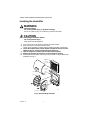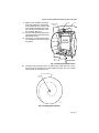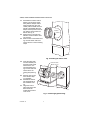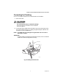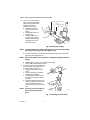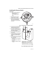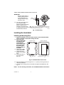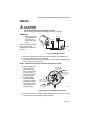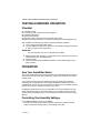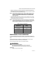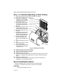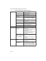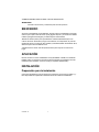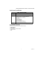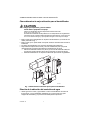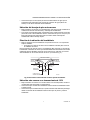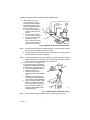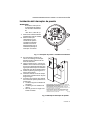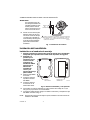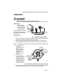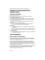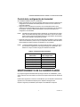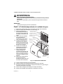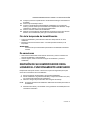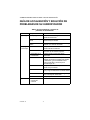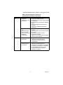
1
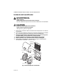
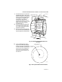
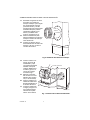
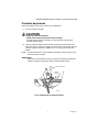
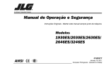
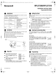
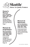
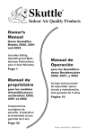
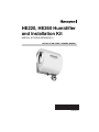
HE220, HE260 Humidifier and Installation Kit (INSTALL KIT SOLD SEPARATELY) INSTALLATION GUIDE / OWNER’S MANUAL Place bar code here 69-2630ES-03 HE220, HE260 HUMIDIFIER AND INSTALLATION KIT IMPORTANT Please read these instructions and keep them in your records. WELCOME To the comfortable world of humidified air. When you use your Honeywell humidifier, notice that your skin is not as dry, and that your scratchy throat and irritated nasal passages that aggravate allergies and asthma are steadily improving. You have also taken the first step in reducing the zapping you create when you walk on your carpet and then touch your TV, computer, metal door knob or your pet. Your furniture and woodwork are also benefitting from the difference that humidified air makes. Congratulations! You have just made a great investment in improving the comfort of your home. APPLICATION This kit contains your new Honeywell HE220 or HE260 Humidifier, H8908 Humidistat and all the accessories required for replacement installation. Installation Kit for new install sold separately (HKIT2A1001). INSTALLATION Preparing for the Installation Be sure to identify all the required (Table 1) accessories (included) and make sure the appropriate tools are available before beginning the installation. 69-2630ES—03 2 HE220, HE260 HUMIDIFIER AND INSTALLATION KIT Included With Humidifier Quantity Table 1. Included Accessories. Accessory 1 Pressure switch 1 H8908 Humidistat 1 bag 1 Saddle Valve Assembly: Saddle valve and top clamp (1) Threaded bottom clamp (1) Bolts (2) Rubber gasket (1) Brass insert (1) Plastic bushing (1) Brass compression ring (1) Brass compression nut (1) Plug-in transformer Required Tools Tools required for installation include: • • • • • Tin snip. Screwdriver. Adjustable or open-end wrench. Drill, punch or awl. Level. 3 69-2630ES—03 HE220, HE260 HUMIDIFIER AND INSTALLATION KIT Determining Best Location for Humidifier CAUTION Temperature and Static Pressure Hazard. Can cause property or equipment damage. Locate humidifier where ambient temperature is between 32°F (0°C) and 160°F (71°C). Do not install humidifier where freezing temperatures could occur. Be sure supply plenum static pressure is no greater than 0.4 in. wc and water pressure is no greater than 124 psi. • Select a location for the humidifier on the supply (warm air stream) plenum. See Fig. 1. • Select a location that cannot damage the air conditioner A-coil during installation. • Do not locate the humidifier on the furnace body. • Allow adequate clearance in front of and above the humidifier so you can easily remove the cover to perform routine maintenance. — Mount the humidifier at least 3 in. (78 mm) above the furnace body to allow adequate space for the solenoid valve and drain line. — Mount the humidifier in a conditioned space to prevent freezing. RN TU RE TAL ON RIZ HO RN TU RE HIG RN TU RE HB OY RN TU RE WN DO O FL OY WB LO M12808A Fig. 1. Typical humidifier installation locations. Selecting Water Supply Location • Use either hard or soft water in the humidifier and either hot or cold water. The water flow rate, with the humidifier running, is 3.5 gal/hr (13 liters/hr) to flush the pad and provide moisture for evaporation. 69-2630ES—03 4 HE220, HE260 HUMIDIFIER AND INSTALLATION KIT • Make sure that the 20 ft (6.2m) of feed water tubing provided is adequate to connect the water supply (saddle valve) with the humidifier solenoid valve. Locating Closest Floor Drain • Select location with access to a floor drain to provide drainage for air conditioner condensation and humidifier drainage. • If you do not have a drain available, we recommend that you install the Honeywell Whole House Drum or Disk Humidifier. Make sure that the 10 ft (3.1m) of drain tubing is adequate to reach from the humidifier drain connection to the floor drain. Selecting Location for Humidistat • Select a location for the humidistat on the return plenum or on the wall in the living space. — Mounting on the return plenum is the easiest installation for the control wiring circuit. For return duct mounting, the humidistat should be mounted upstream from the humidifier or bypass so that it is properly sensing the relative humidity of the living space. Locate the control at least 8 in. (203 mm) upstream from the humidifier in the return air duct. (See Fig. 2.) ALTERNATE LOCATION RETURN AIR RETURN AIR 6 in. (152 mm) MINIMUM 15 in. (381 mm) MINIMUM BEST LOCATION RETURN AIR DUCT M12831 Fig. 2. Selecting duct location for humidistat. Locating Closest 120V Electrical Outlet • Select location with access to an outlet. If not available, contact an electrician to have one installed. • Make sure that the humidifier cord is adequate to reach from the humidifier to the outlet. • Make sure that the 20 ft (6.2m) of thermostat wire is adequate to reach from the humidifier solenoid, to the pressure switch, to the humidistat. 5 69-2630ES—03 HE220, HE260 HUMIDIFIER AND INSTALLATION KIT Installing the Humidifier WARNING Hazardous Voltage Can cause personal injury or equipment damage. Do not cut or drill into any air conditioning or electrical accessory. CAUTION Sharp Edges Installation Hazard. Can cause personal injury. Wear gloves and safety glasses. 1. 2. Turn off power to the air handing system at the circuit breaker. Draw a level line on the plenum in the location chosen for the humidifier. (Leveling assures optimal humidifier performance.) 3. Locate the template (form number 69-2521 included in the box). For the HE220 model, cut out the template along the dotted line. 4. Tape the template in position and trace around the template. 5. Remove the template and carefully cut the rectangular opening. 6. Disassemble the humidifier; remove the cover and take out the humidifier pad assembly. See Fig. 3. WATER FEED NOZZLE HUMIDIFIER PAD ASSEMBLY FRAME HUMIDIFIER HOUSING COVER WATER FEED TUBE SIDEWALL M12304A BY-PASS SIDEWALL Fig. 3. Disassembling humidifier. 69-2630ES—03 6 HE220, HE260 HUMIDIFIER AND INSTALLATION KIT 7. 8. 9. Make sure the humidifier housing is level, then position it in the opening so the plastic tabs are in place on the lower sheet metal edge of the opening. Use pliers, as necessary, to flatten cut edges. See Fig. 4. Secure the humidifier housing to the opening at the top and bottom using sheet metal screws. Use the 6 in. (155 mm) starter collar as a template to mark the opening for the bypass. LEVEL SHEET METAL SCREWS (4) DUCT OPENING TO AIR DUCT PLASTIC TABS (2) Fig. 4. Installing humidifier on duct. 10. Carefully cut the opening for a 6 in. (155 mm) starter collar. See Fig. 5. Use a drill, punch or awl to start the cut in the middle of the circle. Cut in an outward spiral to assist in controlling the cut. 6 IN. ROUND TEMPLATE STARTING HOLE M20172 Fig. 5. Cutting bypass opening. 7 69-2630ES—03 HE220, HE260 HUMIDIFIER AND INSTALLATION KIT 11. 12. 13. Assemble the summer shutoff damper into the starter collar. Verify that the damper rotates freely between the open and closed positions. Make sure the handle is accessible. Mark the damper Closed position as Summer and the Open position as Winter. See Fig. 6. Remove liner to expose foam adhesive. Position starter collar over opening. Slide one end of the flexible ducting over the starter collar and secure with one of the connecting straps. SUMMER WINTER M20173 Fig. 6. Installing the starter collar. 14. 15. 16. 17. Insert the plain collar into the humidifier port and secure with sheet metal screws. Connect the flexible ducting over the collar and secure with a connecting strap. See Fig. 7. Seal the duct connections with duct tape (not included). Reinstall the humidifier pad assembly in the humidifier housing. Hinge the cover in place and secure with the thumbscrew located at the bottom of the cover. 69-2630ES—03 HUMIDIFIER PORT PLAIN COLLAR M20785 Fig. 7. Connecting bypass ducting. 8 HE220, HE260 HUMIDIFIER AND INSTALLATION KIT Connecting the Plumbing Use hot or cold water and either hard or softened water in the humidifier. 1. Shut off the water. CAUTION Chemical Hazard. Can cause personal injury or equipment damage. Do not use any line connected to an air conditioner. Do not use gas line. 2. Use the self-piercing saddle valve (included) to tap into the water supply line at the location selected. See Fig. 8. If tapping into galvanized pipe, drain line and pre-drill 3/17 in. tap for saddle valve. NOTE: The saddle valve is not designed to regulate water flow. The valve is either open or closed. IMPORTANT To prevent debris from clogging the solenoid in-line filter, be sure to install the saddle valve handle pointing toward the ceiling. SCREW DRIVER WATER LINE M20175 Fig. 8. Installing the saddle valve. 9 69-2630ES—03 HE220, HE260 HUMIDIFIER AND INSTALLATION KIT 3. Use 1/4 in. (6 mm) OD tubing and connect the saddle valve to the inlet side of the solenoid valve on the humidifier (see Fig. 9). a. Place the brass compression nut over the tubing. b. Install brass insert into end of tubing. c. Slide the plastic compression ring over the tubing. (Discard copper compression ring provided with valve.) BRASS COMPRESSION NUT PLASTIC COMPRESSION RING BRASS INSERT M20176 Fig. 9. Installing feed tubing. NOTE: To prevent leaking, use plastic (Delrin) sleeve rings with plastic tubing. Use copper sleeve rings only with copper tubing. d. Insert the tubing into the solenoid valve fitting and support the valve while tightening the compression nut. NOTE: Do not over-tighten the compression nut. Moderate tightness prevents leaking. 4. e. Repeat steps a. through d. for solenoid valve fitting. f. Secure tubing with clamps provided. Connect a 1/2 in. (13 mm) drain tube to the humidifier drain fitting and run to the floor drain (see Fig. 10). a. Slide the drain clamp over the tubing. b. Push the tubing over the drain nipple on the humidifier. c. Hand-tighten the clamp around the tubing to secure the humidifier drain. d. Fasten the drain tubing (can use duct tape) along the route to prevent movement and ensure downward slope for correct drainage. NOTE: Cut tubing to correct length so the tubing terminates at the drain. M20177 Fig. 10. Installing the drain tubing. 69-2630ES—03 10 HE220, HE260 HUMIDIFIER AND INSTALLATION KIT Installing the Pressure Switch IMPORTANT Do not install the switch in an area where temperature exceeds rating of -40°F to 190°F (-40°C to 88°C). 1. 2. Disconnect power from the humidifier before installing. Mount the switch vertically with pressure connectors facing down, using provided self-tapping screws to secure the switch to the duct. M27300 Fig. 11. Pressure switch—oriented vertically. 3. 4. 5. 6. 7. The return duct is recommended, however the switch can also be mounted to the supply duct. Cut a 3/4-in. diameter hole in the duct within 10 feet of the switch to ensure the provided tubing reaches the pressure tap elbow. Insert the black rubber gasket into the duct hole. Connect the tubing to the tubing fitting elbow and insert the tubing fitting elbow into the black rubber gasket. Connect the other end of the tubing to the applicable pressure connection on the switch. a. Black connection if installed on the supply b. Grey connection if installed on the return c. Both grey and black if installed on both A B SUPPLY DUCT INSTALL - AIR LINE ONLY TO TAP A, CONNECTED TO THE + PORT ON THE AIR FLOW SWITCH RETURN DUCT INSTALL - AIR LINE ONLY TO TAP B, CONNECTED TO THE – PORT ON THE AIR FLOW SWITCH SUPPLY/RETURN DUCT INSTALL - AIR LINE CONNECTED TO BOTH THE + AND – PORTS ON THE AIR FLOW SWITCH M27303 Fig. 12. Mounting the pressure switch. 11 69-2630ES—03 HE220, HE260 HUMIDIFIER AND INSTALLATION KIT IMPORTANT With low-speed airflow or variable speed systems it is recommended to run tubing to both the supply and return ducts. 8. You may cut the tubing to fit the connection length between the elbow fitting and switch. It is also recommended to secure the hose to existing structures to avoid accidental disconnection. INSIDE OF DUCT 1 1 CONNECT TUBING TO + CONNECTION IF PRESSURE TAP IS MOUNTED TO SUPPLY DUCT. CONNECT TO – IF PRESSURE TAP IS MOUNTED TO RETURN DUCT. M27304 Fig. 13. Install tubing. Installing the Humidistat Installing on Mounting Duct 1. Apply the template to the duct location chosen for the humidistat. Make sure the template is level before drilling the holes. 2. Refer to the template (provided with HUMIDISTAT BASE REAR OF HUMIDISTAT the H8908 Humidistat Installation Instructions) to drill the control assembly opening and mounting holes for the H8908. 3. Remove the H8908 case from the base. 4. Position the foam gasket on the H8908 base. 5. Position the base on the duct with the WIRE SLOT M20179 HUMIDISTAT WIRES arrow up. Fig. 14. Humidistat base and rear view. 6. 7. Secure the base to the duct using the four 1 in. (25 mm) mounting screws provided with humidistat. Connect the low-voltage wires to the leads and replace the H8908 case. See Fig. 14. NOTE: For wall mounting instructions, see the H8908 Installation Instructions. 69-2630ES—03 12 HE220, HE260 HUMIDIFIER AND INSTALLATION KIT WIRING CAUTION Hazardous Voltage. Can cause personal injury or equipment damage. Disconnect power supply before installing or servicing equipment. IMPORTANT All wiring must comply with applicable local code, ordinances and regulations. Wire the humidifier solenoid valve, pressure switch, humidistat and transformer. See Fig. 15. HUMIDISTAT OUTDOOR Humidity Control Régulateur d'humidité TEMPERATURE -30 ¡C -20 ¡F -25 ¡C -10 ¡F -20 ¡C 0 ¡F -10 ¡C +10 ¡F -5 ¡C +20 ¡F Over 0 ¡C Over 20 ¡F HUMIDITY SETTING 15% 20% 25% 30% 35% 40% TRANSFORMER HUMIDIFIER SOLENOID VALVE AIR PRESSURE SWITCH M28974 Fig. 15. Wiring the controls. 1. 2. Run the two-strand thermostat wire from the humidifier to the humidistat, and from the humidistat to the pressure switch. Cut lengths of thermostat wire to reach between components, leaving adequate wire at both ends for connections. NOTE: Humidistat and pressure switch can be wired in any order. 4. At the humidifier, connect the black and white conductors to the two yellow humidifier wires. (The red wires from the humidifier are not used.) At the humidistat, connect both black conductors to the two humidistat terminals. Use a wire nut to connect together the two white conductors. ATTACH ADAPTER WIRE TO HUMIDIFIER C TERMINAL C 1 1 2 2 NORMALLY OPEN (NO) TERMINAL 1/4 (6) X 1/32 (1) THICK QUICK CONNECT 3 ASSEMBLED IN MEXICO 3. COMMON (C) TERMINAL 1/4 (6) X 1/32 (1) THICK QUICK CONNECT 3 3 2 NO NC + PI ATTACH WIRE TO HVAC ADAPTOR C TERMINAL M27398A Fig. 16. Close-up of pressure switch wiring. 5. At the pressure switch, connect the black and white conductors to the C and NO pressure switch terminals (NC terminal is not used). 13 69-2630ES—03 HE220, HE260 HUMIDIFIER AND INSTALLATION KIT TESTING HUMIDIFIER OPERATION Checklist Humidifier is level. Control wiring was reviewed using circuit diagram. Humidifier is plugged in. Feed line has no kinks. Drain line slopes continuously down and ends at floor drain. Water hose inside humidifier is connected to PerfectFlow™ water distribution tray. After installation use the following steps to check the humidifier operation: 1. Turn on the power and the water supply 2. Turn the H8908 Humidistat to On and turn on the heat by setting the thermostat to 10ºF (6ºC) above room temperature. IMPORTANT The furnace blower must be on to activate the humidifier. 3. 4. 5. Make sure that water is flowing out of the drain hose. If water does not flow, see Troubleshooting Your Humidifier section. Check for leaks. Reset the thermostat and H8908 Humidistat to a comfortable setting for automatic operation. OPERATION How Your Humidifier Works Your Honeywell humidifier uses the principle that vapor (evaporated water) is created when warm air blows over a water-soaked area. As the vapor circulates, the relative humidity rises. Your humidity control monitors the relative humidity and activates the humidifier accordingly. The humidifier has a water supply that dispenses water evenly over a humidifier pad. The warm dry air, from the furnace, passes over the humidifier pad and picks up the moist air to circulate it throughout your home. Humidified air feels warmer and more comfortable so you may be able to lower your thermostat heating setpoint, which saves money on your heating fuel bills. The end result is that your humidifier gives you a comfortable environment that is also energy efficient. Controlling Your Humidity Settings Your H8908 Humidistat controls your humidifier. • Choose the humidity control setting using the combination of relative humidity/ outdoor temperature setting scale on your humidity control dial. 69-2630ES—03 14 HE220, HE260 HUMIDIFIER AND INSTALLATION KIT • Match the dial setting to the outdoor temperature to optimize the humidity level while reducing the moisture condensation on your windows. See Table 2 to adjust the humidity control to the recommended setting. NOTE: As the outside temperature drops, a lower humidity setting is recommended to accommodate dewpoint effects. These settings should reduce the accumulation of moisture and ice on windows and other areas of the home. • Adjust the humidity control setting to adjust for indoor activities such as cooking, showering and clothes drying, which can cause excessive levels of humidity that can accumulate moisture on your windows. NOTE: If these activities persist for more than a few hours, set the humidity control to the lowest setting to turn off the humidifier. If the condition does not improve, ventilate your home to remove the moisture. Table 2. Setting Your Humidistat. When Outside Temperature is: Use This Control Setting: -20°F (-29°C) 15 -10°F (-23°C) 20 0°F (-18°C) 25 +10°F (-12°C) 30 +20°F (-7°C) 35 Above 20°F (-7°C) 40 MAINTAINING YOUR HUMIDIFIER A regular maintenance program prolongs the life of your humidifier and makes your home more comfortable. The frequency of cleaning depends on the condition of your water. You can use either hard or soft water in your humidifier, but hard water mineral deposits are more difficult to clean than soft water deposits. Use the following procedure to clean your Honeywell humidifier. WARNING Serious Personal Injury Hazard. Can cause electrical shock and injury from moving parts. Disconnect power and shut off water supply before removing cover. IMPORTANT Never oil any part of the humidifier. 15 69-2630ES—03 HE220, HE260 HUMIDIFIER AND INSTALLATION KIT Every 1 to 3 Months (Depending on Water Quality) 1. 2. 3. 4. 5. 6. 7. 8. 9. 10. 11. 12. 13. 14. 15. 16. 17. 18. Disconnect the power and turn off the humidifier water supply. Remove the humidifier cover. See Fig. 17. PerfectFlo™ WATER Remove the humidifier pad DISTRIBUTION TRAY assembly from the humidifier by grasping the top of the tray WATER FEED NOZZLE and pulling it toward you. Pull one side of the humidifier HUMIDIFIER PAD ASSEMBLY pad assembly frame toward you and remove the tray from HUMIDIFIER HOUSING the frame. Gently pinch the water nozzle WATER FEED TUBE catches inward until you can lift the water nozzle off the tray. SIDEWALL Slide the humidifier pad out of COVER the frame. Carefully remove any mineral deposits from the tray and frame. Be sure the frame drain hole has nothing blocking it. Disconnect the drain hose from the drain fitting on the bottom of the humidifier housing. Clean the drain fitting, if necessary. Bend the drain hose to loosen any mineral deposits. BYPASS SIDEWALL Flush the drain hose with presM12327A surized water (a running tap) to clean the hose. Fig. 17. Cleaning your humidifier. Reattach the drain hose to the drain fitting. Slide the humidifier pad back into the frame. Snap the water nozzle back on the tray. Reattach the tray to the frame. Place the humidifier pad assembly in the humidifier housing and press until the assembly is completely seated. Be careful not to pinch or kink the water feed tube. Replace the humidifier cover. Verify the humidifier operation by following the steps in the Checking Your Humidifier for Correct Operation section. End of Humidification Season • Clean the humidifier and shut it off at the end of the heating season. • Use Every 1 to 3 Months section steps to shut down for the season. IMPORTANT Be sure the humidifier power is off. 69-2630ES—03 16 HE220, HE260 HUMIDIFIER AND INSTALLATION KIT Vacation • When leaving on vacation, turn off the humidifier water supply and your humidistat. • When you return, turn on the humidifier water supply and reset your humidistat. CHECKING YOUR HUMIDIFIER FOR CORRECT OPERATION After winter startup or servicing, use the following steps to check your humidifier operation: 1. 2. 3. Turn on the humidifier power and water supply. Turn the humidistat to its highest setting and set the thermostat to 10°F (6°C) above the room temperature. Observe that water is flowing out of the drain hose. NOTE: The furnace blower must be running to activate the humidifier. 4. Reset the thermostat and humidistat to a comfortable setting for automatic operation. TROUBLESHOOTING YOUR HUMIDIFIER Table 3. Troubleshooting Humidifier. Problem Water leakage What to look for What to do Leaking joints. Shut off water. Tighten connections. Brass tubing inserts Verify that brass tubing inserts are used. Saddle valve leaking. Verify rubber pad is installed on saddle valve. 17 69-2630ES—03 HE220, HE260 HUMIDIFIER AND INSTALLATION KIT Table 3. Troubleshooting Humidifier. (Continued) No water to drain. Electrical Verify control circuit wiring. Check all connections. Humidistat Turn humidistat up and down and listen for contact to click. Humidifier power Verify that outlet has power. Solenoid After verifying other wiring components, turn on furnace fan, turn humidistat up and down, and listen for solenoid to click. Plumbing Verify plumbing connections. Check for kinks. Saddle valve Verify that needle pierces water line and then backs out needle to open valve. Humidifier Remove cover and verify that water flows into distribution tray. Drain tubing Verify no obstructions. Air leakage Check duct joints Seal with duct tape. Low humidity Furnace blower not operating. • Reset circuit breaker or check for blown fuse. • Check that the furnace power is on. • Check all external wiring connections. • Check the humidity control setting. • Call a professional heating contractor. Rapid air changes. Drafts (cold air is dry and is an added load to the humidifier). • Keep doors and windows closed. • Close fireplace damper when not in use. • Keep exhaust fan running time to a minimum. • Seal around doors and windows. Condensation on walls. • Turn off humidity control and water until condensation is completely evaporated. Heavy condensation on windows. • Turn humidity control down low enough to eliminate condensation caused by moisture from bathing, mopping, cooking, etc. If moisture persists, more ventilation is needed. High humidity 69-2630ES—03 18 HE220, HE260 HUMIDIFIER AND INSTALLATION KIT LIMITED ONE-YEAR WARRANTY Honeywell warrants this product, excluding humidifier pad, to be free from defects in the workmanship or materials, under normal use and service, for a period of one (1) year from the date of purchase by the consumer. If, at any time during the warranty period, the product is defective or malfunctions, Honeywell shall repair or replace it (at Honeywell’s option) within a reasonable period of time. If the product is defective, return it, with a bill of sale or other dated proof of purchase, to the retailer where you purchased it. This warranty does not cover removal or reinstallation costs. This warranty shall not apply if it is shown by Honeywell that the defect or malfunction was caused by damage which occurred while the product was in the possession of a consumer. Honeywell’s sole responsibility shall be to repair or replace the product within the terms stated above. HONEYWELL SHALL NOT BE LIABLE FOR ANY LOSS OR DAMAGE OF ANY KIND, INCLUDING ANY INCIDENTAL OR CONSEQUENTIAL DAMAGES RESULTING, DIRECTLY OR INDIRECTLY, FROM ANY BREACH OF ANY WARRANTY, EXPRESS OR IMPLIED, OR ANY OTHER FAILURE OF THIS PRODUCT. Some states do not allow the exclusion or limitation of incidental or consequential damages, so this limitation may not apply to you. THIS WARRANTY IS THE ONLY EXPRESS WARRANTY HONEYWELL MAKES ON THIS PRODUCT. THE DURATION OF ANY IMPLIED WARRANTIES, INCLUDING THE WARRANTIES OF MERCHANTABILITY AND FITNESS FOR A PARTICULAR PURPOSE, IS HEREBY LIMITED TO THE ONE YEAR DURATION OF THIS WARRANTY. Some states do not allow limitations on how long an implied warranty lasts, so the above limitation may not apply to you. This warranty gives you specific legal rights, and you may have other rights which vary from state to state. If you have any questions concerning this warranty, please write to Honeywell Customer Care, 1985 Douglas Drive, Minneapolis, MN55422. In Canada, write Retail Products ON15-02H, Honeywell Limited/Honeywell Limitée, 35 Dynamic Drive, Toronto, Ontario M1V 4Z9. 19 69-2630ES—03 HE220, HE260 HUMIDIFIER AND INSTALLATION KIT Automation and Control Solutions Honeywell International Inc. 1985 Douglas Drive North Golden Valley, MN 55422 customer.honeywell.com ® U.S. Registered Trademark © 2011 Honeywell International Inc. 69-2630ES—03 M.S. Rev. 09-11 Printed in United States Humidificadores HE220 o HE260 y kit de instalación (EL KIT DE INSTALACIÓN SE VENDE POR SEPARADO) GUÍA DE INSTALACIÓN/MANUAL DEL PROPIETARIO Place bar code here 69-2630ES-03 HUMIDIFICADORES HE220 O HE260 Y KIT DE INSTALACIÓN IMPORTANTE Lea estas instrucciones y consérvelas para consulta posterior. BIENVENIDO Al mundo confortable del aire humidificado. Cuando utiliza su humidificador Honeywell, observe que su piel no está tan seca, que la garganta rasposa y los conductos nasales irritados que agravan las alergias y el asma mejoran continuamente. También ha dado el primer paso para disminuir la electricidad estática que crea cuando camina en la alfombra y luego toca el televisor, la computadora, el pomo de metal de la puerta o su mascota. Sus muebles y la madera también se benefician de la diferencia que el aire humidificado crea. ¡Felicitaciones! Ha hecho una estupenda inversión para mejorar el confort de su hogar. APLICACIÓN Este kit contiene su nuevo humidificador Honeywell HE220 o HE260, el humidistato H8908 y todos los accesorios necesarios para la instalación de reemplazo. El kit de instalación para instalación nueva se vende por separado (HKIT2A1001). INSTALACIÓN Preparación para la instalación Cerciórese de identificar todos los accesorios necesarios que se incluyen (Tabla 1) y tener disponibles los implementos adcuados antes de comenzar la instalación. 69-2630ES—03 2 HUMIDIFICADORES HE220 O HE260 Y KIT DE INSTALACIÓN Incluido con el humidificador Cantidad Tabla 1. Accesorios incluidos. Accesorio 1 Interruptor de presión 1 Humidistato H8908 1 bolsa 1 Ensamblaje de válvula de asiento: Válvula de asiento y abrazadera superior (1) Abrazadera inferior roscada (1) Pernos (2) Junta de goma (1) Inserto de latón (1) Cojinete plástico (1) Aro de compresión en latón (1) Tuerca de compresión en latón (1) Transformador enchufable Herramientas necesarias Las herramientas necesarias para la instalación incluyen: • • • • • Tijera de hojalata. Destornillador. Llave ajustable o de extremo abierto. Taladro o punzón. Nivel. 3 69-2630ES—03 HUMIDIFICADORES HE220 O HE260 Y KIT DE INSTALACIÓN Cómo determinar la mejor ubicación para el humidificador CAUTION Peligro por temperatura y presión estática. Puede dañar la propiedad o el equipo. Ubique el humidificador donde la temperatura ambiente esté entre 32 °F (0 °C) y 160 °F (71 °C). No instale el humidificador donde pudiesen ocurrir temperaturas de congelamiento. Cerciórese de que la presión estática del plenum de alimentación no sea mayor de 0.4 in en la columna de agua y que la presión de agua no sea mayor de 124 psi. • Elija un lugar para el humidificador en el plenum de alimentación (corriente de aire cálido). Consulte la Fig. 1. • Elija un lugar que no pueda dañar el serpentín A del aire acondicionado durante la instalación. • No ubique el humidificador en la estructura del sistema de calefacción. • Deje suficiente espacio libre al frente y sobre el humidificador para que pueda retirar fácilmente la cubierta para efectuar el mantenimiento de rutina. — Monte el humidificador al menos 3 in (78 mm) por encima del sistema de calefacción para permitir suficiente espacio para la válvula solenoide y la tubería de drenaje. — Monte el humidificador en un espacio acondicionado para evitar el congelamiento. RE TAL RE RE RN TO O RE RN TO O ON RIZ HO RN TO RN TO O A M OR AF AT A PL ALT O D MA OR AF AT O TE UJ FL DEN N CE S E JA BA PL MS12808 Fig. 1. Ubicaciones de instalación típicas para el humidificador. Elección de la ubicación del suministro de agua • Utilice agua dura o suave y agua caliente o fría en el humidificador. El índice de flujo de agua, con el humidificador trabajando, es 3.5 gal/h (13 litros/h) para empapar la almohadilla y proporcionar humedad para la evaporación. 69-2630ES—03 4 HUMIDIFICADORES HE220 O HE260 Y KIT DE INSTALACIÓN • Cerciórese de que los 20 ft (6.2m) de tubería de alimentación de agua que se suministran sean adecuados para conectar el suministro de agua (válvula de asiento) con la válvula solenoide del humidificador. Ubicación del drenaje de piso más cercano • Elija la ubicación con acceso a un drenaje de piso para proporcionar la salida de la condensación del aire acondicionado y el drenaje del humidificador. • Si no existe un drenaje disponible, recomendamos que instale el tambor Honeywell para toda la casa o el humidificador de disco. Cerciórese de que los 10 ft (3.1m) de tubería de drenaje sean adecuados para la conexión desde el drenaje del humidificador hasta el drenaje del piso. Elección de la ubicación del humidistato • Elija una ubicación para el humidistato en el plenum de retorno o en la pared del espacio habitable. — El montaje en el plenum de retorno es la instalación más fácil para el circuito de cableado de control. Para el montaje en el ducto de retorno, el humidistato debe colocarse por encima del humidificador o desviador de modo que esté adecuadamente detectando la humedad relativa del espacio habitable. Ubique el control al menos 8 in (203 mm) por encima del humidificador en el conducto de aire de retorno. (Consulte la Fig. 2) UBICACIÓN ALTERNA AIRE DE RETORNO AIRE DE RETORNO MÍNIMO 6 in (152 mm) MÍNIMO 15 in. (381 mm) UBICACIÓN PREFERENTE CONDUCTO DE AIRE DE RETORNO MS12831 Fig. 2. Elección de la ubicación del conducto para el humidistato. Ubicación más cercana a un tomacorriente de 120V • Elija la ubicación con acceso a un tomacorriente. Si no está disponible, contacte a un electricista para que instale un tomacorriente. • Cerciórese de que el cable del humidificador alcance desde el humidificador hasta el tomacorriente. • Cerciórese de que el cable de 20 ft (6.2 m) del termostato sea adecuado para llegar desde el solenoide del humidificador hasta el interruptor de presión y hasta el humidistato. 5 69-2630ES—03 HUMIDIFICADORES HE220 O HE260 Y KIT DE INSTALACIÓN Instalación del humidificador ADVERTENCIA Voltaje peligroso Puede causar lesiones personales o daño al equipo. No corte ni taladre en ningún accesorio de aire acondicionado o de electricidad. CAUTION Riesgo de bordes afilados en la instalación. Puede ocasionar lesiones personales. Utilice guantes y gafas de seguridad. 1. Desconecte el suministro eléctrico del sistema de manejo de aire en el interruptor de circuito. 2. Trace una línea nivelada en el plenum en la ubicación elegida para el humidificador. (La nivelación garantiza el desempeño óptimo del humidificador). 3. Ubique la plantilla (forma número 69-2521 que se incluye en la caja). Para el modelo HE220, corte la plantilla por la línea punteada. 4. Encinte la plantilla en su posición y trace alrededor de la plantilla. 5. Retire la plantilla y corte cuidadosamente la abertura rectangular. 6. Desensamble el humidificador; retire la cubierta y saque el ensamble de la almohadilla del humidificador. Consulte la Fig. 3. BOQUILLA DEL TUBO DE ALIMENTACIÓN ENSAMBLE DE LA ALMOHADILLA DEL HUMIDIFICADOR MARCO CARCASA DEL HUMIDIFICADOR CUBIERTA TUBO DE ALIMENTACIÓN DE AGUA PARED LATERAL MS12304 PARED DE DERIVACIÓN Fig. 3. Desensamblaje del humidificador. 69-2630ES—03 6 HUMIDIFICADORES HE220 O HE260 Y KIT DE INSTALACIÓN 7. 8. 9. Cerciórese de que la carcasa del humidificador esté a nivel y seguidamente colóquela en la abertura de modo que las pestañas plásticas queden en su lugar en el borde inferior de la lámina metálica de la abertura. Use un alicate según sea necesario, para aplanar los bordes cortados. Consulte la Fig. 4. Fije la carcasa del humidificador en la abertura de la parte superior e inferior utilizando tornillos para lámina metálica. Utilice el collarín de arranque de 6 in (155 mm) como plantilla para marcar la abertura del desviador. TORNILLOS PARA LÁMINA METÁLICA (4) NIVEL CONDUCTO ABERTURA HACIA EL CONDUCTO DE AIRE PESTAÑAS PLÁSTICAS (2) TUBERÍA DE DRENAJE MS20171 Fig. 4. Instalación del humidificador en un conducto. 10. Corte cuidadosamente la abertura para un collarín de arranque de 6 in. (155 mm). Consulte la Fig. 5. Utilice un taladro o punzón para iniciar el corte en la mitad del círculo. Corte en forma de espiral hacia afuera para permitir el control del corte. PLANTILLA REDONDA DE 6 IN (155 mm) AGUJERO DE ARRANQUE MS20172 Fig. 5. Corte para la abertura del desviador. 7 69-2630ES—03 HUMIDIFICADORES HE220 O HE260 Y KIT DE INSTALACIÓN 11. 12. 13. Ensamble el regulador de cierre de verano en el collarín de arranque. Verifique que el regulador rote libremente entre las posiciones abierto y cerrado. Cerciórese de que la manija esté accesible. Marque la posición cerrada del regulador como Verano y la abierta como Invierno. Consulte la Fig. 6. Retire el revestimiento para exponer el adhesivo con espuma. Coloque el collarín de arranque sobre la abertura. Coloque un extremo del conducto flexible sobre el collarín de arranque y fije con uno de los zunchos de conexión. VERANO INVIERNO MS20173 Fig. 6. Instalación del collarín de arranque. 14. 15. 16. 17. Inserte el collarín corriente en el puerto del humidificador y fíjelo con tornillos para lámina metálica. Coloque el conducto flexible sobre el collarín y fije con un zuncho de conexión. Consulte la Fig. 7. Selle las conexiones del conducto con cinta adhesiva para conductos (no se suministra). Vuelva a instalar el ensamble de la almohadilla del humidificador en la carcasa del mismo. Coloque la cubierta en su lugar y asegure con los tornillos de pulgar ubicados en la parte inferior de la cubierta. 69-2630ES—03 PUERTO DEL HUMIDIFICADOR COLLARÍN CORRIENTE MS20785 Fig. 7. Conexión del conducto de derivación. 8 HUMIDIFICADORES HE220 O HE260 Y KIT DE INSTALACIÓN Conexión de plomería Utilice agua caliente o fría y dura o suave en el humidificador. 1. Corte el suministro de agua. CAUTION Peligro de sustancias químicas. Puede causar lesiones personales o daño al equipo. No utilice ninguna tubería conectada a un equipo de aire acondicionado. No utilice tubería de gas. 2. Utilice la válvula de asiento autoperforante que se incluye para insertar en la tubería de agua en la ubicación elegida. Consulte la Fig. 8. Si utiliza un tubo galvanizado, purgue la tubería y pretaladre 3/17 in (4.4 mm) para la válvula de asiento. NOTA: La válvula de asiento no está diseñada para regular el flujo de agua. La válvula está abierta o cerrada. IMPORTANTE Para evitar que los desechos obstruyan el filtro de la tubería del solenoide, instale la manija de la válvula de asiento orientada hacia el techo. DESTORNILLADOR TUBERÍA DE AGUA MS20175 Fig. 8. Instalación de la válvula de asiento. 9 69-2630ES—03 HUMIDIFICADORES HE220 O HE260 Y KIT DE INSTALACIÓN 3. Utilice tubería de 1/4 in (6 mm) de diámetro externo y conecte la válvula de asiento al lado de la toma de la válvula del solenoide del humidificador (consulte la Fig. 9). a. Coloque la tuerca de compresión de latón sobre la tubería. b. Instale el inserto de latón en el extremo de la tubería. c. Coloque el aro de compresión plástico sobre la tubería. (Deseche el aro de compresión de cobre que se suministra con la válvula). TUERCA DE COMPRESIÓN DE LATÓN ARO DE COMPRESIÓN PLÁSTICO INSERTO DE LATÓN MS20176 Fig. 9. Instalación de la tubería de alimentación. NOTA: para evitar fugas, utilice los aros plásticos (Delrin) con tubería plástica. Utilice aros de cobre únicamente con tubería de cobre. d. Inserte la tubería en el acople de la válvula del solenoide y soporte la válvula mientras aprieta la tuerca de compresión. NOTA: 4. no apriete demasiado la tuerca de compresión. Un ajuste moderado evita fugas. e. Repita desde el paso a. hasta el d. para el acople de la válvula del solenoide. f. Fije la tubería con las abrazaderas que se suministran. Conecte un tubo de drenaje de 1/2 in (13 mm) al acople de drenaje del humidificador y hágalo llegar hasta el drenaje de piso (consulte la Fig. 10). a. Coloque la abrazadera del drenaje sobre la tubería. b. Empuje la tubería sobre la boquilla de drenaje del humidificador. c. Apriete a mano la abrazadera alrededor de la tubería para asegurar el drenaje del humidificador. d. Fije la tubería de drenaje (puede utilizar cinta adhesiva para conductos) por toda la ruta para evitar el movimiento y lograr una pendiente descendente para el M20177 drenaje adecuado. Fig. 10. Instalación de la tubería de drenaje. NOTA: corte la tubería al largo adecuado de modo que finalice en el drenaje. 69-2630ES—03 10 HUMIDIFICADORES HE220 O HE260 Y KIT DE INSTALACIÓN Instalación del interruptor de presión IMPORTANTE No instale el interruptor en un área donde la temperatura exceda la clasificación de -40 a 190 °F (-40 a 88 °C). 1. 2. Desconecte la electricidad del humidificador antes de instalar. Monte el interruptor verticalmente con los conectores de presión orientados hacia abajo, utilizando los tornillos autoperforantes que se suministran para fijar el interruptor al conducto. M27300 Fig. 11. Interruptor de presión—orientado verticalmente. 3. 4. 5. 6. 7. Se recomienda el conducto de retorno; sin embargo el interruptor también puede montarse en el conducto de suministro. Haga un agujero de ¾ in (19 mm) de diámetro en el conducto en el trayecto de 10 ft (3 m) desde el interruptor para lograr que la tubería que se suministra alcance el codo de la toma de presión. Inserte la junta de goma negra en el agujero del conducto. Conecte la tubería al codo de acople de la tubería e inserte este en la junta de goma negra. Conecte el otro extremo de la tubería a la conexión de presión pertinente en el interruptor. a. Conexión negra si se instala en el suministro b. Conexión gris si se instala en el retorno c. Tanto la gris como la negra si se instala en ambas A B INSTALACIÓN DEL CONDUCTO DE SUMINISTRO: TUBERÍA DE AIRE ÚNICAMENTE A LA TOMA A, CONECTADA AL PUERTO + EN EL INTERRUPTOR DE FLUJO DE AIRE INSTALACIÓN DEL CONDUCTO DE RETORNO: TUBERÍA DE AIRE ÚNICAMENTE A LA TOMA B, CONECTADA AL PUERTO – EN EL INTERRUPTOR DE FLUJO DE AIRE INSTALACIÓN DEL CONDUCTO DE SUMINISTRO/RETORNO: TUBERÍA DE AIRE CONECTADA A LOS PUERTOS + Y – EN EL INTERRUPTOR DE FLUJO DE AIRE MS27303 Fig. 12. Montaje del interruptor de presión. 11 69-2630ES—03 HUMIDIFICADORES HE220 O HE260 Y KIT DE INSTALACIÓN IMPORTANTE Con sistemas de flujo de aire de baja velocidad o de velocidad variable se recomienda pasar la tubería tanto al conducto de suministro como al de retorno. 8. Puede cortar la tubería para adecuar el largo de la conexión entre el codo de acople y el interruptor. También se recomienda fijar la manguera a las estructuras existentes para evitar la desconexión accidental. DENTRO DEL CONDUCTO 1 1 CONECTE LA TUBERÍA A LA CONEXIÓN + SI LA TOMA DE PRESIÓN ESTÁ MONTADA EN EL CONDUCTO DE SUMINISTRO. CONECTE A LA CONEXIÓN – SI LA TOMA DE PRESIÓN ESTÁ MONTADA EN EL CONDUCTO DE RETORNO. MS27304 Fig. 13. Instalación de la tubería. Instalación del humidistato Instalación en el conducto de montaje 1. 2. 3. 4. 5. 6. 7. Aplique la plantilla a la ubicación del conducto elegido para el humidistato. Compruebe que la plantilla esté nivelada antes de perforar los agujeros. Refiérase a la BASE DEL HUMIDISTATO PARTE POSTERIOR DEL HUMIDISTATO plantilla que se suministra con las instrucciones de instalación del humidistato H8908 para perforar la abertura del ensamble del control y los agujeros de montaje para el H8908. Retire la caja H8908 de la base. Coloque la junta de espuma en la base RANURA CABLES DEL PARA CABLES HUMIDISTATO MS20179 del H8908. Coloque la base en el conducto con la flecha hacia arriba. Fig. 14. Base del humidistato y vista posterior. Fije la base al conducto utilizando los cuatro tornillos de montaje de 1 in (25 mm) que se proporcionan con el humidistato. Conecte los cables de bajo voltaje a los cables conductores y reemplace la caja del H8908. Consulte la Fig. 14. NOTA: Para las instrucciones de montaje en pared, refiérase a las instrucciones de instalación del H8908. 69-2630ES—03 12 HUMIDIFICADORES HE220 O HE260 Y KIT DE INSTALACIÓN CABLEADO CAUTION Voltaje peligroso. Puede causar lesiones personales o daño al equipo. Desconecte el suministro eléctrico antes de instalar o prestar servicio al equipo. IMPORTANTE Todo el cableado debe cumplir con la normativa, ordenanzas y regulaciones locales pertinentes. Cablee la válvula del solenoide del humidificador, el interruptor de presión, el humidistato y el transformador. Consulte la Fig. 15. HUMIDISTATO OUTDOOR Humidity Control Régulateur d'humidité TEMPERATURE -30 ¡C -20 ¡F -25 ¡C -10 ¡F -20 ¡C 0 ¡F -10 ¡C +10 ¡F -5 ¡C +20 ¡F Over 0 ¡C Over 20 ¡F HUMIDITY SETTING 15% 20% 25% 30% 35% 40% TRANSFORMADOR VÁLVULA DEL SOLENOIDE DEL HUMIDIFICADOR INTERRUPTOR DE PRESIÓN DE AIRE MS28974 Fig. 15. Cableado de los controles. 2. Pase el cable de dos conductores del termostato desde el humidificador hasta el humidistato y desde este hasta el interruptor de presión. Corte tramos del cable del termostato para que alcancen los componentes dejando adecuada cantidad de cable en ambos extremos para las conexiones. NOTA: 3. El humidistato y el interruptor de presión pueden cablearse en cualquier orden. En el humidificador, conecte los FIJE EL CABLE DEL ADAPTADOR AL TERMINAL DEL conductores negro y HUMIDIFICADOR C blanco a los dos cables amarillos del TERMINAL COMÚN (C) humidificador. (Los DE 1/4 (6) X 1/32 (1) C 1 cables rojos del DE ESPESOR PARA CONEXIÓN RÁPIDA humidificador no se 2 3 utilizan.) En el humidistato, 3 2 TERMINAL NORMALMENTE conecte los dos con- ABIERTO (NO) DE 1/4 (6) X 1/32 (1) NO NC DE ESPESOR PARA ductores negros a los CONEXIÓN RÁPIDA + PI dos terminales del FIJE EL humidistato. Utilice un CABLEE HACIA ADAPTADOR EL TERMINAL C empalme para cables MS27398 DEL CVAA para juntar los dos conductores blancos. Fig. 16. Detalle del cableado del interruptor de presión. ASSEMBLED IN MEXICO 1. 1 2 4. 5. 3 En el interruptor de presión, conecte los conductores negro y blanco a los terminales del interruptor de presión C y NO (el terminal NC no se utiliza). 13 69-2630ES—03 HUMIDIFICADORES HE220 O HE260 Y KIT DE INSTALACIÓN PRUEBA DE FUNCIONAMIENTO DEL HUMIDIFICADOR Lista de comprobación El humidificador está nivelado. El cableado de control ha sido revisado utilizando el diagrama de circuito. El humidificador está enchufado. La tubería de alimentación no tiene torceduras. La tubería de drenaje desciende continuamente y termina en el drenaje de piso. La manguera de agua dentro del humidificador está conectada a la bandeja de distribución de agua PerfectFlow™. Después de la instalación siga estos pasos para revisar el funcionamiento del humidificador: 1. Active el suministro de electricidad y de agua. 2. Encienda el humidistato H8908 y la calefacción colocando el termostato 10 °F (6 °C) por encima de la temperatura de la habitación. IMPORTANTE El soplador del sistema de calefacción deberá estar encendido para activar el humidificador. 3. 4. 5. Cerciórese de que el agua fluya hacia afuera en la manguera de drenaje. Si el agua no fluye, refiérase a la sección de Localización y solución de problemas de su humidificador. Revise si hay fugas. Reinicie el termostato y el humidistato H8908 a una graduación confortable para el funcionamiento automático. FUNCIONAMIENTO Cómo trabaja su humidificador Su humidificador Honeywell utiliza el principio de que el vapor (agua evaporada) se crea cuando el aire cálido sopla sobre un área empapada con agua. A medida que circula el vapor, la humedad relativa se eleva. Su control de humedad monitoriza la humedad relativa y activa el humidificador cuando sea necesario. El humidificador tiene un suministro de agua que dispensa agua uniformemente sobre una almohadilla del humidificador. El aire seco cálido del sistema de calefacción pasa sobre la almohadilla del humidificador y recoge el aire húmedo para que circule por toda su casa. El aire humidificado se siente más cálido y más confortable de modo que puede bajar el punto de ajuste del termostato, lo cual le ahorra dinero en sus facturas de calefacción. El resultado final es que su humidificador le brinda un ambiente confortable que también le ahorra energía. 69-2630ES—03 14 HUMIDIFICADORES HE220 O HE260 Y KIT DE INSTALACIÓN Control de la configuración de humedad Su humidistato H8908 controla su humidificador. • Elija la configuración de control de humedad utilizando la escala de combinación de configuración de humedad relativa/temperatura en exteriores de su selector de control de humedad. • Haga coincidir la configuración del selector con la temperatura exterior para optimizar el nivel de humedad mientras disminuye la condensación de humedad en sus ventanas. Consulte la tabla 2 para ajustar el control de humedad con la configuración recomendada. NOTA: a medida que la temperatura exterior descienda, se recomienda una configuración de humedad más baja para lograr la adecuación al punto de condensación. Estas configuraciones deben disminuir la acumulación de humedad y hielo en las ventanas y otras áreas de la casa. • Regule la configuración del control de humedad para actividades en interiores tales como cocinar, ducharse y secar la ropa, lo cual puede ocasionar niveles excesivos de humedad que pueden acumular condensación en sus ventanas. NOTA: si estas actividades persisten por más de algunas horas, coloque el control de humedad en la graduación más baja para apagar el humidificador. Si la situación no mejora, ventile su hogar para eliminar la humedad. Tabla 2. Configuración del humidistato. Cuando la temperatura externa sea: Coloque el control en esta configuración: -20°F (-29°C) 15 -10°F (-23°C) 20 0°F (-18°C) 25 +10°F (-12°C) 30 +20°F (-7°C) 35 Superior a 20°F (-7°C) 40 MANTENIMIENTO DE SU HUMIDIFICADOR Un programa regular de mantenimiento prolonga la vida de su humidificador y hace que su casa sea más confortable. La frecuencia de limpieza depende de la calidad del agua. Puede utilizar agua dura o suave en su humidificador, pero los depósitos minerales del agua dura son más difíciles de limpiar que los depósitos del agua suave. Emplee el siguiente procedimiento para limpiar su humidificador Honeywell. 15 69-2630ES—03 HUMIDIFICADORES HE220 O HE260 Y KIT DE INSTALACIÓN ADVERTENCIA Peligro de lesiones personales graves. Puede causar descarga eléctrica y lesiones provenientes de las partes en movimiento. Desconecte la electricidad y corte el suministro de agua antes de retirar la tapa. IMPORTANTE Nunca aceite ninguna parte del humidificador. Cada 1 a 3 meses (dependiendo de la calidad del agua) 1. 2. 3. 4. 5. 6. 7. 8. 9. 10. 11. 12. 13. Desconecte la electricidad y cierre el suministro de agua del humidificador. Retire la cubierta del humidificador. Consulte la Fig. 17. Retire el ensamble de la BANDEJA DE DISTRIBUCIÓN DEL AGUA PerfectFlo™ almohadilla del humidificador tomando la parte superior de BOQUILLA DEL TUBO DE ALIMENTACIÓN DE AGUA la bandeja y halándola hacia usted. ENSAMBLE DE LA ALMOHADILLA DEL HUMIDIFICADOR Hale un lado del ensamble de la almohadilla del CARCASA DEL HUMIDIFICADOR humidificador hacia usted y TUBO DE retire la bandeja del marco. ALIMENTACIÓN DE AGUA Comprima suavemente los PARED LATERAL retenedores de la boquilla CUBIERTA del agua hacia adentro hasta que pueda extraer la boquilla del agua de la bandeja. Deslice la almohadilla del humidificador hacia afuera para retirarla del marco. Retire cuidadosamente cualquier depósito de minerales de la bandeja y del marco. Cerciórese de que el agujero de drenaje del marco no tenga un obstáculo que lo bloquee. PARED DE Desconecte la manguera de DERIVACIÓN MS12327 drenaje del acople de drenaje en la parte inferior de la carcasa del humidificador. Fig. 17. Limpieza del humidificador. Limpie el acople de drenaje, si fuese necesario. Doble la manguera de drenaje para aflojar los depósitos minerales. Enjuague la manguera de drenaje con agua presurizada (de un grifo de agua corriente) para limpiar la manguera. Vuelva a fijar la manguera de drenaje en el acople de drenaje. Deslice la almohadilla del humidificador nuevamente en el marco. 69-2630ES—03 16 HUMIDIFICADORES HE220 O HE260 Y KIT DE INSTALACIÓN 14. 15. 16. 17. 18. Coloque a presión la boquilla del tubo de alimentación del agua nuevamente en la bandeja. Vuelva a fijar la bandeja al marco. Coloque el ensamble de la almohadilla del humidificador en la carcasa del mismo y presione hasta que el ensamble esté completamente asentado. Tenga cuidado de no pellizcar o torcer el tubo de alimentación. Vuelva a colocar la cubierta del humidificador. Verifique el funcionamiento del humidificador siguiendo los pasos de la sección Revisión de su humidificador para lograr el funcionamiento adecuado. Fin de la temporada de humidificación • Limpie el humidificador y desconéctelo al final de la temporada de uso de la calefacción. • Efectúe los pasos de la sección cada 1 a 3 meses para desconectarlo por la temporada. IMPORTANTE Cerciórese de que la electricidad que alimenta el humidificador esté desconectada. De vacaciones • Desconecte la electricidad cuando esté de vacaciones y cierre el suministro de agua del humidificador y del humidistato. • Cuando regrese, active el suministro de agua al humidificador y reinicie el humidistato. REVISIÓN DE SU HUMIDIFICADOR PARA LOGRAR EL FUNCIONAMIENTO ADECUADO Después del arranque de invierno o del servicio, ejecute los siguientes pasos para revisar el funcionamiento de su humidificador: 1. 2. 3. Active el suministro de electricidad y de agua del humidificador. Gire el humidistato a su graduación más alta y coloque el termostato 10°F (6°C) por encima de la temperatura de la habitación. Observe si el agua fluye hacia afuera de la manguera de drenaje. NOTA: 4. el soplador del sistema de calefacción deberá estar encendido para activar el humidificador. Reinicie el termostato y el humidistato a una graduación confortable para el funcionamiento automático. 17 69-2630ES—03 HUMIDIFICADORES HE220 O HE260 Y KIT DE INSTALACIÓN GUÍA DE LOCALIZACIÓN Y SOLUCIÓN DE PROBLEMAS DE SU HUMIDIFICADOR Tabla 3. Guía de localización y solución de problemas del humidificador. Problema Lo que debe buscar Fuga de agua Juntas que goteen. Cómo resolverlo Corte el suministro de agua. Apriete las conexiones. Insertos de latón para Verifique que los insertos de latón para tubería tubería se hayan utilizado. Fugas en la válvula de Verifique que la almohadilla de goma se haya asiento instalado en la válvula de asiento. No hay agua Electricidad en el drenaje. Verifique el cableado del circuito de control. Revise todas las conexiones. Humidistato Gire el humidistato hacia arriba y hacia abajo y escuche que el contacto haga clic. Electricidad en el humidificador Verifique que el tomacorriente tenga electricidad. Solenoide Después de verificar otros componentes del cableado, encienda el ventilador del sistema de calefacción, gire el humidistato hacia arriba y hacia abajo y escuche que el solenoide haga clic. Plomería Verifique las conexiones de plomería. Revise si hay torceduras. Válvula de asiento Verifique que la aguja atraviesa la tubería de agua y luego se retira hacia la válvula abierta. Humidificador Retire la cubierta y verifique que el agua fluye hacia la bandeja de distribución. Tubería de drenaje Verifique que no existan obstrucciones. Fuga de aire 69-2630ES—03 Revise todas las uniones del conducto Cinta adhesiva para conductos. 18 HUMIDIFICADORES HE220 O HE260 Y KIT DE INSTALACIÓN Tabla 3. Guía de localización y solución de problemas del humidificador. (Continued) Humedad baja Humedad alta El soplador del • Reinicie el interruptor de circuito o verifique sistema de si hay algún fusible quemado. calefacción no está • Verifique que haya energía en los sistemas funcionando. de calefacción. • Revise todas las conexiones de cableado externo. • Revise la configuración del control de humedad. • Llame a un contratista de calefacción profesional. Cambios rápidos de aire. Corrientes de aire (el aire frío está seco y es una carga añadida al humidificador). • Mantenga las puertas y las ventanas cerradas. • Cierre el regulador de la chimenea cuando no la utilice. • Mantenga el ventilador extractor funcionando al mínimo. • Selle todos los espacios alrededor de las puertas y de las ventanas. Condensación en las paredes. • Apague el control de humedad y cierre el suministro de agua hasta que la condensación se haya evaporado completamente. Mucha condensación en las ventanas. • Disminuya el control de humedad lo suficiente como para eliminar la condensación provocada por la humedad en el baño, por la limpieza con trapeador, por la actividad en la cocina, etc. Si persiste la humedad, es necesario aumentar la ventilación. 19 69-2630ES—03 HUMIDIFICADORES HE220 O HE260 Y KIT DE INSTALACIÓN GARANTÍA LIMITADA DE UN AÑO Honeywell garantiza por el período de un (1) año a partir de la fecha de compra por parte del consumidor, que este producto, sin incluir la almohadilla del humidificador, no presentará defectos en los materiales ni en la mano de obra, en condiciones normales de uso y de servicio. Si en cualquier momento, durante el período de vigencia de la garantía, se determina que el producto está defectuoso o no funciona adecuadamente, Honeywell lo reparará o lo reemplazará (a elección de Honeywell) en un período razonable. Si el producto está defectuoso, devuélvalo con la factura de venta u otra prueba de compra con la fecha, al distribuidor donde lo adquirió. Esta garantía no cubre los gastos de remoción ni de reinstalación. Esta garantía no se aplicará si Honeywell demuestra que el defecto o funcionamiento inadecuado fueron causados por daños que se produjeron mientras el producto estaba en posesión de un consumidor. La única responsabilidad de Honeywell será la de reparar o reemplazar el producto dentro de los términos mencionados anteriormente. HONEYWELL NO SERÁ RESPONSABLE DE LA PÉRDIDA NI DAÑO DE NINGÚN TIPO, QUE INCLUYE CUALQUIER DAÑO INCIDENTAL O CONSECUENTE QUE RESULTE, DIRECTA O INDIRECTAMENTE, DE CUALQUIER INCUMPLIMIENTO DE CUALQUIER GARANTÍA, EXPRESA O IMPLÍCITA, O DE CUALQUIER OTRA FALLA DE ESTE PRODUCTO. Algunos estados no permiten la exclusión o limitación de los daños incidentales o consecuentes, por lo que esta limitación podría no aplicarse en su caso. ESTA GARANTÍA ES LA ÚNICA GARANTÍA EXPRESA QUE HONEYWELL OTORGA SOBRE ESTE PRODUCTO. LA DURACIÓN DE CUALQUIERA DE LAS GARANTÍAS IMPLÍCITAS, INCLUIDAS LAS GARANTÍAS DE APTITUD E IDONEIDAD PARA UN FIN DETERMINADO, QUEDA, POR EL PRESENTE, LIMITADA A LA DURACIÓN DE UN AÑO DE ESTA GARANTÍA. Algunos estados no permiten limitaciones en relación a la duración de una garantía implícita, de manera tal que la limitación anterior puede no aplicarse en su caso. Esta garantía le otorga derechos legales específicos, pero es posible que usted goce de otros derechos que varían de un estado a otro. Si tiene preguntas acerca de esta garantía, escriba a Honeywell Customer Care, 1985 Douglas Drive, Minneapolis, MN55422. En Canadá, escriba a Retail Products ON1502H, Honeywell Limited/Honeywell Limitée, 35 Dynamic Drive, Toronto, Ontario M1V 4Z9. Automatización y control desenlace Honeywell International Inc. 1985 Douglas Drive North Golden Valley, MN 55422 customer.honeywell.com ® Marca Registrada en los Estados Unidos © 2011 Honeywell International Inc. todos Los Derechos Reservados 69-2630ES—03 M.S. Rev. 09-11 Impreso en Estados Unidos