1
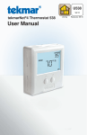
518_Q
03/13
Thermostat 518
Zoning
Replaces: New
Quick Setup Guide
1. Location
Interior
Wall
5 feet
1.5 m
Exterior
Wall
2. Remove Mounting Base
3. Installation to Wall
Thermostat
Base
Thermostat
Front
Wall
A Watts Water Technologies Company
1 of 8
© 2013
518_Q - 03/13
4. Installation to Gang Box
Stud
Adapter Plate 012
Thermostat
Front
Thermostat
Base
3 1/4”
(83 mm)
Gang
Box
5. Wiring
Zone
Valve
Install field
jumper wire
R to Rh
RC
518
Optional
Slab Sensor 079
No Power
C
R Rh W1 S1 Com
24 V
LN
6. User Interface
A Watts Water Technologies Company
2 of 8
© 2013
518_Q - 03/13
7. Critical Settings
The following settings are essential to the successful operation of the heating system.
Press
+
Together
Display
• Press and hold down both the
and
buttons for 3
seconds to change from one step to the next.
• Release both buttons once the step has been reached.
• Press the
or the
button to change the setting, if
available.
• Press and hold down both the
and
buttons for 3
seconds to go to the next step, OR
• After 15 seconds of no button activity, the display goes
back to normal operation.
Setting
User settings.
MODE
Select heat or off.
UNITS
Select the temperature units in degree Fahrenheit or Celsius.
BACK LIGHT
Select when the display back light should operate. Options are
Off, Auto, and On. Auto operates the backlight for 30 seconds
after a keystroke.
F
SET FLOOR
Set the floor minimum temperature. Available when an auxiliary
floor sensor is connected and the built-in room temperature
sensor is on.
TYPE
Device Type number. Hold the
version.
ESCAPE
Release the
A Watts Water Technologies Company
and
button to view the software
buttons to return to the home screen.
3 of 8
© 2013
518_Q - 03/13
Display
Setting
Installer settings. Press the
and
buttons together for 5 more seconds.
AUXILIARY SENSOR
Select the type of auxiliary sensor. Available when an auxiliary
sensor is automatically detected. NONE = no auxiliary sensor,
ROOM = Indoor Sensor, OUT = Outdoor Sensor, FLOR = Slab
Sensor
ROOM SENSOR
Select if the built-in room temperature sensor is on or off. The builtin room sensor can only be disabled when an auxiliary room or slab
sensor is connected.
Room
F
MAX
FLOOR MAXIMUM
Set the floor maximum temperature in order to protect the floor
covering. Suggested settings: Tile = 90°F (32°C), Wood Floor =
85°F (29°C)
ESCAPE
Release the
and
buttons to return to the home screen.
For a full list of settings and operational details, please refer to the
thermostat Installation and Operation Manual 518_D that is available from
www.tekmarControls.com
Product design, software and literature are Copyright ©2013 by tekmar Control Systems Ltd.,
A Watts Water Technologies Company. Head Office: 5100 Silver Star Road, Vernon, B.C.
Canada V1B 3K4, 250-545-7749, Fax. 250-545-0650 Web Site: www.tekmarControls.com
All specifications are subject
to change without notice
4 of 8
518_Q - 03/13.
518_Q
03/13
Thermostat 518
Zonage
Remplace:
Nouveau
Guide d’installation rapide
1. Emplacement
Mur intérieur
5 pi.
1,5 m
Mur extérieur
2. Retirez la base de montage
3. Installation au mur
Façade du
thermostat
Base de
thermostat
Mur
Une société de Watts Water Technologies
5 of 8
© 2013
518_Q - 03/13
4. Installation à la boîte électrique
Plaque
adaptrice 012
Façade du
thermostat
Base de
thermostat
Goujon
3 1/4”
(83 mm)
Boîte
électrique
5. Filage
soupape
de zone
cavalier entre “R”
et “Rh”. Mise au
champ
RC
518
sonde de sol
optionnelle 079
No Power
C
R Rh W1 S1 Com
24 V
LN
6. Interface d’utilisateur
Une société de Watts Water Technologies
6 of 8
© 2013
518_Q - 03/13
7. Paramètres critiques
Les paramètres suivants sont essentiels au bon fonctionnement du système
de chauffage.
Appuyez
+
Ensemble
Afficheur
• Appuyez et maintenez les deux boutons
pendant 3
secondes pour passer d’une étape à l’autre.
• Relâchez les deux boutons
une fois que l’étape a été
atteinte.
• Appuyez sur le bouton
ou
pour changer le réglage si
disponible.
• Appuyez et maintenez les deux
boutons pour 3
secondes pour passer à l’étape suivante ou
• Après 15 secondes d’inactivité, l’écran revient à un
fonctionnement normal.
Paramètres
Paramètres d’utilisateur
MODE
Sélectionnez chauffage ou désactivez.
UNITÉS
Sélectionnez les unités de température en Celsius ou Fahrenheit.
RÉTRO-ÉCLAIRAGE
Sélectionnez lorsque le rétro-éclairage de l’affichage devrait
fonctionner. Les options sont “Off”, “Auto”, et “On”. La sélection
“Auto” maintient le rétro-éclairage fonctionnel durant 30
secondes suite à touche d’un bouton.
F
RÉGLAGE DE TEMPÉRATURE AU SOL
Réglez la température au sol minimale. Disponible quand une
sonde de plancher auxiliaire est connectée et la sonde de
température ambiante est active.
TYPE
Numéro de type de dispositif. Maintenez le bouton
afficher la version du logiciel.
pour
RETOUR ÉCRAN D’ACCUEIL
pour revenir à l’écran d’accueil.
Relâchez les boutons
Une société de Watts Water Technologies
7 of 8
© 2013
518_Q - 03/13
Afficheur
Paramètres
Paramètres d’installateur. Appuyez sur les touches
plus de 5 secondes.
ensemble pour
SONDE AUXILIAIRE
Sélectionnez le type de sonde auxiliaire.
Disponible quand une sonde auxiliaire est automatiquement
détectée. NONE = pas de sonde auxiliaire, ROOM = sonde
intérieure, FLOR = sonde de dalle
SONDE D’AMBIANCE
Choisir si la sonde intégrée de la température ambiante est
active ou inactive. La sonde d’air ambiante peut être désactivée
seulement lorsqu’une sonde auxiliaire intérieure ou de dalle est
connectée.
Room
F
MAX
RÉGLAGE DE TEMPÉRATURE MAXIMALE DU SOL
Réglez la température maximale au sol afin de protéger son
revêtement. Paramètres proposés sont: Tuiles = 90°F (32°C),
Planchers de bois = 85°F (29°C)
RETOUR ÉCRAN D’ACCUEIL
Relâchez les boutons
pour revenir à l’écran d’accueil.
Pour une liste complète des paramètres et les détails opérationnels, s’il
vous plaît se référer à l’installation du thermostat et mode d’emploi qui sont
disponibles à partir de www.tekmarControls.com
Conception de produit, logiciel et littérature sont des droits réservés ©2013 par tekmar Control
Systems Ltd., Une société de Watts Water Technologies. Bureau chef: 5100 Silver Star Road, Vernon,
B.C. Canada V1B 3K4, 250-545-7749, Téléc: 250-545-0650 Site Web: www.tekmarControls.com
Toutes spécifications sont sujettes à changements
sans préavis. Imprimé au Canada.
8 of 8
518_Q - 03/13.