1
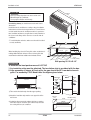
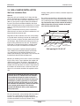
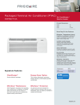
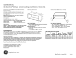
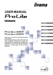
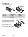
6RWU0-03A
Installation of unit
2.4 Installation of unit
The PTAC and its components are as shown below.
12
1
1
3
1
13
1
1
4
1
2
1
5
1
6
1
8
10
1
14
11
1
7
1
9
1. WALL SLEEVE
2. FRONT GRILLE
3. AIR FILTER
4. AIR INTAKE
5. AIR DISCHARGE
6. VERTICAL AIR DEFLECTOR
(HORIZONTAL LOUVER)
7. EVAPORATOR
8. CONTROL PANEL
9. POWER CORD
10. COMPRESSOR
11. BASE PAN
12. BRACE
13. CONDENSER
14. OUTDOOR GRILLE (ARCHITECTURAL GRILLE)
Use the correct wall sleeve and outdoor grille
This unit is designed to be installed in the insulated wall sleeve.
When you place the unit into the existing sleeve, the wall sleeve
used to mount the new unit must be in good structural condition
and have the outdoor grille that securely attaches to the sleeve
or the flange of the sleeve to secure the new air conditioner.
PTAC
I
N
Installation
Unit
D
O
Remove the vertical deflectors in the existing grille to reduce
condenser air recirculation that can cause the unit to poor cooling or heating and component failure.
Wall Sleeve
O
R
With the LG sleeve, you can maintain the best performance of
the new air conditioner.
If you keep the existing sleeve, you run the risk of poor performance or product failure. This is not covered
under the LG warranty.
Outdoor Grille
Front Grille
(Shipped with the unit)
56
Installation of unit
6RWU0-03A
CAUTION
1,066 mm
(42")
• There are sharp edges that can cause serious cuts.
• When lifting the air conditioner.
Use 2 people to lift.(the unit is heavy)
For existing sleeve, you should measure the wall sleeve
dimensions.
Install the new air conditioner according to these installation
instructions to achieve the best performence. The wall sleeve
used to mount the new air conditioner must be in good structural condition and have a rear grille that securely attaches to
the sleeve or the flange of the sleeve to secure the new air
conditioner.
406 mm
(16")
349 mm
(13 3/4")
537mm(21")
• To avoid vibration and noise, make sure the unit is installed
securely and firmly.
42"
1/2" SQ. HOLE (2 REQ'D.)
13-
3/4
"
2-3/4"
When installing the sleeve & Front grille, make certain there is
nothing within 20" Back & front of sleeve & front grille, that
would interfere with heat radiation and exhaust air flow.
1/2"
1-1/2" TYP
16"
4"
5-5/8"
6"
36"
1/2" DIA.
HOLE (3 REQ'D.)
21"
Wall opening 16-1/4"x42-1/4"
Recommended
To maintain the best performance of LG PTAC
1. An insulation strip must be attached. The insulation strip is provided with the box.
2. After assembly of sleeve & Front grille, the gap should be 20" from both sleeve &
grille. For assembly PTAC Model refer the digram given below.
GRILLE
INSULATION
13-3/4"
WALL
COOLED
AIR
TOP VIEW
SLEEVE
HEAT
RADIATION
INTAKE
AIR
42"
ROOM
CABINET
1/4" Bubble
of the level
WALL
Over 20"
1) Take out the insulation strip from the upper packing.
2) Attach the insulation strip onto the rear upper side of the
wall sleeve.
3) Insulation strip prevents the exhaust air from re-entering
from either side of condenser space which may decrease
the cooling efficiency of condenser.
280 mm
(11")
Front
Over 20"
Insulation Strip
Sleeve
Rear
57
PTAC
Installation
6RWU0-03A
Installation of unit
2.5 WALL SLEEVE INSTALLATION
Wall Case Installation Data
General
Generally, units are installed 3" to 5" above the floor
(flush to finished floor installation is possible) as near to
the center of the room as possible; underneath a window or a glass panel is typical. Normal installation of
the wall case allows installation flexibility; from flush
with the finished interior wall to a minimum of 1/4" of the
wall case extending beyond the finished exterior of the
building.
Special consideration must be given to installations
where the wall case does not extend a minimum of 1/4"
beyond the finished exterior wall.
Regardless of the installation, there are several things
to consider when selecting a location for installing the
unit. For instance, drapery location could interfere with
air discharge, and placement of furniture may have an
impact on the performance of the unit. The following
information is intended to minimize installation problems and assure you of a trouble-free installation.
Refer to last page for required wall opening dimensions. Minimum recommended interior and exterior
case projection for standard wall thicknesses are
shown in the drawings in this manual. The case may be
installed flush with the finished indoor wall.
framing, moving electrical outlets, and other expensive
modifications.
For existing construction it is important that carpentry,
masonry and electrical work be performed by competent, qualified personnel. Since installations in existing construction may involve removal of building
material from the structure, location of the wall
case must be precisely done.
42"
1/2" SQ. HOLE (2 REQ'D.)
13-
3
/4"
2-3/4"
1-1/2" TYP
1/2"
16"
4"
6"
36"
21"
1/2" DIA.
HOLE (3 REQ'D.)
Wall opening 16-1/4"x42-1/4"
Mounting an outdoor grille or louver section to the building face may cause a space between the outdoor coil
and the louver section. Air splitters, aligned with the
ends of the outdoor coil, must be installed between the
outdoor coil inlet and outlet air streams. Gaps between
the outdoor coil and the louver section may allow condenser air recirculation and affect the operation of the
unit.
The wall case should be level from side to side
and from level to 1/4 bubble tilt to the outdoors.
The condensate disposal system in the unit is
designed to dissipate the condensate water generated during cooling operation in accordance
with ARI standards and actually uses this water
for maximum unit efficiency. A level unit will also
insure proper performance of the Internal
Condensate Removal (ICR) system optional on
heat pump units.
For new construction, early planning with the architect
is necessary. Unit location, electrical connection
locations, and wall openings of proper dimension are
essential to avoid the necessity of rework, fillers,
Installation
PTAC
58
Installation of unit
6RWU0-03A
The outside edge of the wall case should extend at least
1/4" beyond the outside wall.
This is necessary for proper caulking, to prevent sealing
thedrain holes in the rear flange of the wall case, and to
facilitate the installation of an accessory drain, if used.
Preparation of the front grille
Carefully remove shipping tape from the front grille.
The wall case should be level from side to
side and from level to 1/4 bubble tilt to the
outdoors. The condensate disposal system in
the unit is designed to dissipate the condensate water generated during cooling operation
in accordance with ARI standards and actually uses this water for maximum unit efficiency. A level unit will also insure proper performance of the Internal Condensate Removal
(ICR) system optional on heat pump units.
Shipping Tape
Brick, Frame, Stucco and Shingle
Construction
For new construction, the opening for the wall case should
be framed and inserted into the opening during construction. Lintels should be used when the building material is
heavy and is not self supporting (such as brick). The wall
case will fit an opening of six courses of standard brick or
five courses of jumbo brick. Wall framing in this type construction is normally on 16" centers and the wall case will fit
a framed opening spanning three 16" O.C. 2" x 4" stud
spaces.
For existing construction the indoor and outdoor wall will
need to be cut out, allowing for clearances of 1/8" on all
sides of the wall case. Work should begin on the inside wall.
Cut the correct dimensions and mark (using drill holes) the
outside wall from each corner of the inside cutout. Studding
that interferes with the opening must be removed and a suitable frame constructed to secure the wall case and provide
adequate support for case and chassis.
Preparation of the Wall Case for All Types of
Construction
As shipped, the LG wall sleeve is ready for installation.
Do not remove the stiffener from inside the wall case or the
weather closure panel from the outside face of the wall case
until the outdoor grille and chassis are ready to be installed.
Installation of Wall Case in Wall Opening
2. The wall case should be secured to the wall at both
sides.
Use a minimum of two screws or other fastening device
on each side. See Figure 2 page 60. Mark the wall case
on each side 2" from the bottom and 2" from the top at a
point where basic wall structure is located. Drill wall case
and use fasteners appropriate for wall construction. All
holes for fasteners in the side of the wall case must be at
least 2" up from the bottom of the wall case.
Never fasten screws or put other holes in the bottom
of the wall case.
If the wall opening is greater than the case dimensions,
spacers must be used on the sides between the wall
case and the wall support structure to prevent distorting
the wall case.
3. Caulk or gasket the entire opening on the outside
between the wall case and exterior wall surface (4 sides)
to provide total water and air seal.
4. Caulk or gasket room-side opening between wall case
and interior wall surface (4 sides). Opening beneath or
around the wall case can allow outdoor air to leak into the
room resulting in increased operating costs and improper
room temperature control.
Care should be taken in location of electrical supply
entry in relationship to wall sleeve to assure access to
receptacle or junction box once unit is installed.
1. Position the wall case into the wall. The room side edge of
the wall case should be at least flush with the finished wall
for line cord installations and permanent connection installations when no sub-base is used, and should project into the
room at least 2-3/8" when a sub-base is used. If the minimum exterior dimensions are not met, refer to page 60.
59
PTAC
Installation
6RWU0-03A
Installation
Installation of unit
PTAC
60
61
PTAC
WALL RECEPTACLE
(BY OTHERS)
2" MIN.
CAULK*
POWER SUPPLY
CONDUIT
OUTDOOR
GRILLE
STEEL LINTEL
CAULK*
1/4"
MIN.
WALL CASE
MOUNTING SCREWS
BY INSTALLER
20-7/8" (RAB71)
21"
(RAB77)
RAB71 13-3/4"
RAB77 13-7/8"
*Caulk around perimeter of wall case all four sides
where it joins the building - Interior and Exterior
.
FINISHED FLOOR
OR TOP OF
CARPET
CAULK*
ROOM
CABINET
CAULK*
Cord Set Connected
FINISHED FLOOR
OR TOP OF
CARPET
3" MIN.
5" MAX.
FRAME AND BRICK VENEER INSTALLATION
WALL SECTION – DETAILED SIDE VIEW
3-11/16"
SIDE CHANNEL
WALL CASE
2" MIN.
MOUNTING SCREWS
BY INSTALLER
POWER SUPPLY CONDUIT
(ALTERNATE ENTRY)
CAULK*
SUB-BASE
(RAK204)
1-5/16"
ROOM
CABINET
CAULK*
2-3/8"
LINTEL
Sub-Base Connected
*Caulk around
perimeter of wall
case all four
sides where it
joins the building
- Interior and
Exterior .
OUTDOOR
GRILLE
CAULK*
1/4"
Installation of unit
6RWU0-03A
Installation
6RWU0-03A
Installation of unit
• unit installation
1. Remove the shipping screw from the ventilation door.
2. Remove the front gille by pulling it out at the bottom
to release it, then lift it up along the unit top front.
3. Slide the unit into the wall sleeve and secure with
6 screws through the unit flange holes.
4. Reinstall the front grille by hooking the top over the
unit top, then pushing it in at the bottom.
O
O
R
N
D
I
I
N
D
O
PTAC
O
R
I
N
D
O
Installation
O
R
• Failure to follow this caution may result in
equipment
damage or improper operation.
• Blocking indoor(curtain or bedclothes etc.) or
outdoor discharge air could cause premature
failure of unit.
62
Installation of unit
6RWU0-03A
ELECTRICAL SAFETY
IMPORTANT
(PLEASE READ CAREFULLY)
PREFERRED METHOD
FOR THE USER'S PERSONAL SAFETY, THIS APPLIANCE MUST BE PROPERLY GROUNDED
The power cord of this appliance is equipped with a threeprong (grounding) plug. Use this with a standard three-slot
(grounding) wall power outlet to minimize the hazard of electric shock. The customer should have the wall receptacle and
circuit checked by a qualified electrician to make sure the
receptacle is properly grounded.
Ensure proper ground
exists before use
DO NOT CUT OR REMOVE THE THIRD (GROUND)
PRONG FROM THE POWER PLUG.
FUSE – Use a time – delay fuse or circuit breaker. Refer to the nameplate for proper power supply requirements.
Use Wall Receptacle
Power Supply
CAUTION
1. Do not use an extension cord with this unit.
2. When the unit is in the OFF position, the power supply to the electrical controls is still energized.
3. Disconnect the power to the unit before servicing
the unit.
4. Remove the power cord from the wall receptacle.
5. Remove or turn off the protective device (fuses or circuit breaker).
Wirings including installation of the receptacle must comply with the
NEC and local codes, local regulations.
Use 15 AMP. time
delay fuse or 15 AMP.
Circuit breaker.
Standard 208/230V, 3-wire
grounding receptacle rated 15A
Use 20 AMP. time
delay fuse or 20 AMP.
Circuit breaker.
Standard 208/230V, 3-wire
grounding receptacle rated 20A
(2500W Heater ơ15Amp
Circuit Breaker)
Use 30 AMP. time
delay fuse or 30 AMP.
Circuit breaker.
Standard 208/230V, 3-wire
grounding receptacle rated 30A
FUSE- Use a time-delay fuse or circuit breaker. Refer to the nameplate
for proper power supply requirements.
Use 20AMP,time delay
fuse or 20AMP
Circuit breaker
Standard 265V grounding
receptacle rated 20A
Standard 265V grounding
receptacle rated 25A
(2000W Heater ơ15Amp
Circuit Breaker)
Use 25AMP,time delay
fuse or 25AMP
Circuit breaker
Installation(for 60Hz)
• Electric installation requirement for personal safety:
• This equipment must be properly connected to ground.
Standard 265V grounding
receptacle rated 30A
Use 30AMP, time delay
fuse or 30AMP
Circuit breaker
• Under no circumstances cut or break the grounder conductor.
• We recommend not to use an extension wire or any adaptor with this product.
• Follow the national or local electric codes.
• If the power supply does not fulfill the specifications previously mentioned, call an authorized electrician.
• The aluminum wired in the houses may bring about some problems, call an authorized electrician.
• This unit requires a separated power supply that works only for this application.
63
PTAC
Installation