1
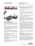
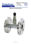
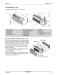
Dishwasher Service Manual
Type:
DW5A/DW5B/DW5E/DW5F/DW5H/DW5AL/DW
5HL
Commonly Used Tools
For the sake of safe and efficient manipulation, you should prepare and learn to use the
following tools prior to servicing the dishwater:
Cross screwdriver,
Common screwdriver,
Torque spanner,
OTK caliper and universal meter.
Attention: never measure the resistance of live cord. Otherwise, you measuring device
may be damaged.
The trouble shooting
Problems
E1
Reasons
Directions
The water supply is turned off
Inlet hose is bended
Turn the water supply on
Put the hose in the right way
The water pressure is too low
Minimum water pressure of
0.03Mpa
Water valve is damaged
Water valve or hose is blocked
E2
E3
E4
`Salt leakage
(for equipped
with softener)
Not operate
after push start
key
Fill water not
stop
Too less fill
water
Dishwasher
runs with door
open
Motor hums but
not start or run.
Damaged or defective drain pump
Drain hose is obstructed or bended
Replace the water valve
Disassemble and clean the water
valve or hose
Replace the drain pump
Put the hose in the right way
Working switch wring is wrong connected
The floater base Is too dirty ang cause
floater is stickled
Defective the electric control
The voltage too low
Damaged the thermostat 2 or the fuse for
the heating element
Repair the wiring
Replace or clear the floater base or
floater
Replace the electric control
Minimum voltage of 198V
Replace the thermostat 2 or the
fuse
The wring is wrong connected
Thermostat 1 is Damaged
Damaged the heating element
Repair the wiring
Replace the thermostat 1
Replace the heating element
Defective the electric controller
Replace the electric controller
Water valve is damaged
The protection switch wring is wrong
connected
Working switchwring is wrong connected
Defective the electric control
The cover of the softener is loosed
Replace the water valve
Repair the wiring
Repair the wiring
Replace the electric control
Tighten the cover
The o-ring of the cover is inversed
Replace the o-ring
Door switch is damaged
Replace door swich
Door lock is damaged
Replace door lock
The wring is wrong connected
Defective electric control
Water valve is damaged
Defective electric control
Repair the wiring
Replace electric control
Replace the water valve
Replace electric control
Dishwasher not level
Level the dishwasher
Door switch wring is wrong connected
Repair the wiring
Defective electric control
Replace electric control
Defective motor bearings
Defective motor capacitor.
Damaged or defective wiring
Improper motor voltage.
Improper motor voltage.
Motor shaft binding.
Defective motor capacitor.
Replace motor.
Replace motor capacitor.
Repair wiring
Replace motor.
Replace motor.
Replace motor.
Replace motor capacitor.
Motor trips out
on internal
thermal
overload
Motor windings shorted.
protector
The fuse for the Defective or too dirty the inner of the
heating
bobber base
Replace motor.
Replace or clear the bobber base
element break
Water siphons
out
Noisy pump
assembly
Poor clearing
Poor drying
Defective electric control
Replace electric control
Drain hose loop is too low.
Move drain hose to proper height.
Drain hose connected to a floor drain not
properly vented.
Install a vent air gap at counter top.
Debris in bottom of tub sump area
Clean out the sump area
Pump parts are not properly installed
The sump or the filter is obstructed
Inspect the pump and correct and
installation errors
Clear the sump and filter
The filter is not in position
Put filter and micro filter in position
The filter is distortioned
Dishes or knife/fork or something else
stifled spray arm
Repair or replace filter
Rotating the spray arm before start
Improper loading of dishes, pots etc.
Instruct the customer on proper
loading of the dishes, refer to the
owners manual
Too less of the detergent
The wrong wash program be chosen
Defective detergent/rinse module
Replace the detergent/rinse
Spray arm is blocked
Too few of the inlet water
Defective pump
No salt in the softener
Improper loading of dishes, pots etc.
The wrong wash program be chosen
Clear or replace the spray arm
Check as the ERROR 2
Replace the pump
Add salt to the softener
Instruct the customer on proper
loading of the dishes, refer to the
owners manual
Defective detergent/rinse module
Replace the detergent/rinse
Note: in the narration of this manual, the number in brackets behind the part stands for
the serial number of the part in the explosion diagram. The actual configuration may be
different.
III. Check of Performance: Loading of Dishes
Many of the performance failures of the dishwasher are not the result of echanical
troubles. And the unsatisfactory washing result can usually be corrected without any
service. This manual deals first with the problems in performance. To have satisfactory
washing result, you have to use the machine correctly. First thing first, the dishes shall
be placed in a correct manner. If the machine works well and the washing result is
unsatisfactory, you should check the layout of the dishes as follows:
1
Load the dishes as instructed in the user's manual.
2
Preparation of the dishes such as dumping the remaining food, and removing
from the dishes food lumps, starches in particular, shall be done prior to loading.
3
The dishes shall face the water flow from the spray arm for free washing. Do not
place the dishes in an overlapped way.
4
Load heavy pans and large soup bowls downwards. If the upper racks are barred
from water flows, do not place articles on them any more.
5
Leave some space in the front of the wire basket so that the water flow may wash
out the dishwater detergent from the detergent trough in the inner door.
6
On the fork/knife rack, the tableware shall be placed with handle down evenly. Do
not load there the articles that may fall out from the bottom.
IV. Check of Performance: Detergent and Brightness Liquid
The water (pressure, hardness and temperature) and the detergent are the major
elements that affect the washing effect of the machine. Choose the right detergent and
dosage according to the local water condition, you will have satisfactory washing result.
1
Use only the fresh and dry detergent of the designated brand. Outdated detergent
will reduce the washing effect.
2
Contact the local water supply company for the water condition, if applicable. The
higher the water hardness is, the more detergent shall be used.
3
Check the brightness liquid in the dispenser and add without delay if it is
insufficient. The brightness liquid helps the water to drip, making the dishes easy to dry
and curbing the formation of water specks on the surface of the dishes.
V. Power cord
The power cord of the dishwasher usually has a
three-pin plug. Connect the power supply as
instructed in the user's manual. If the dishwasher
does not work, the power cord might be in the
fault. Most of the power cord troubles arise from
damaged cord or loose connection, and are
visible.
Attention:
To avoid electric shock, the power socket and
power cord shall be well grounded. Never use two-hole
conversion connector that has no ground terminals.
Removal and replacement:
1
Disconnect the power prior to check.
2
Check the power plug. Improper connection may lead to bad contact.
3
Pull out the power plug in one stroke. Never pull at the power cord or use a knife
or other sharp tools that may cut the cord.
4
Check the power plug for overheat caused damage, corrosion or looseness. In
case of troubles, remove the outer casing first, then the rear panel and replace the
power cord (see Process 6).
5
Open the power cord clamp , remove the old power cord and replace a new one
with terminals. Secure the power terminals to the connection terminals, and replace the
power cord clamp.
6
Replace the rear panel and the outer casing.
VI. Removal of Outer Casing, Control Panel, Rear
This dishwasher is completely sealed. In order to repair internal parts, you have to
remove the outer casing before you can check and repair the parts. An ohmmeter and
the ability to read circuit diagrams are needed in this step.
Removal and replacement:
1
Turn all the switches OFF and pull out the power cord plug.
2
Remove the three screws on the sides of the outer casing.
3
Open the door, and remove the six screws in the front of the inner container (see
fig. 1 below). Note: do not mix these stainless steel screws with the other ordinary ones.
4
Remove the seven screws in the back of the outer casing (see fig. 2 below).
5
Remove the screws in position D in fig. 2 below and take away the rear panel.
6
Lift up and away the outer casing from the dishwasher, check and repair the
internal parts.
7
Remove the six screws from the control panel holder (60) (see fig. 3 below) and
the two stainless steel screws in the inner container (see fig. 1 below), and pull out the
control panel.
8
Turn the dishwasher upside down, remove all the screws in the bottom pan, open
the cord clamp and remove the bottom pan.
VII. Check Internal Connecting Wire
The internal connecting wire connects the I/O PCB the power switch , the inlet valve ,
the heating elements and other electric elements together. The wires shall be kept
intact. Any damage to the wire may cause overheat and result in broken wire. Common
troubles to the internal connecting wire are broken wire, bad connection terminal contact,
and connection terminal insulation layer damages. To repair the dishwasher, the ground
shall be connected. When an electric component is replaced, check whether the ground
is connected again. This is a crucial step to avoid electric shock and short circuit.
Attention:
To replace electric cord, use the cord of the same temperature resistance and
specifications. The specifications and temperature rise are marked on the cord.
Removal and replacement:
1
Disconnect the power prior to check.
2
Open the outer casing, and, if necessary, remove the bottom panel.
3
Check the wires and connectors and replace the damaged ones.
VIII. Door Lock Assembly
The working mechanism of the door lock is
that the linkage bolts up the door hook,
which, in its turn, presses the micro switch
spring in the lock assembly to form a closed
circuit. The lock mechanism consists of the
door lock holder , the slider and the micro
switch When the door is opened, the door
hook is withdrawn to release the micro switch,
cutting the power supply for open door
protection.
In case of worn out slider, micro switch failure or deformed micro switch spring,
troubles may occur and the dishwasher will stop to work as usual.
Removal and replacement:
1
Pull out the power cord plug prior to servicing the door lock mechanism.
2
Remove the outer casing.
3
If micro switch failure, disconnect the micro switch, remove the two screws and
replace a new micro switch.
4
If deformed micro switch spring, adjust the spring with a nipper pliers so that the
micro switch returns to its original position when the slider is released, and the micro
switch closes when the slider is pressed tight, or replace the micro-switch.
IX. Electrical controller
The electrical controller of the
dishwasher consists of a control PCB
and I/O PCB, it controls the various
operations of the dishwasher
automatically. The output cords of
the electrical controller are in
different colors. With the circuit
diagram in hand, you can track the
circuit from the electrical controller to
any element. The electrical controller
is a very reliable unit. In case of
dishwasher troubles, check other
causes first before focusing on and
replacing the electrical
The power switchcontroller. Such as the power
Removal and replacement:switch, it is a push-button switch.
1
Pull out the power cord plug.
2
Remove the outer casing.
3
Press the power switch and check with an ohmmeter whether the normally open
terminal is closed. If it is not closed, replace the switch.
4
Remove the control panel, unscrew the screws to remove the defect switch, and
replace with a new one.
5
Connect the wires behind the switch and check if they are connected fast.
X. Protection Switch and Working Switch
Removal and replacement: The inlet water flux of the dishwasher is implemented by a
float switch which composed of
two micro switches. The up
switch is the working level. The
other controls the protection
level . The working level is set at
88-92mm above the sump bottom,
and the protection level is 5mm
or more below the brink of the
inner container. The check and
adjustment of the switch:
If switch trouble is suspected, check whether the dishwasher is level. If it is in level
position, remove the outer casing.Add water to the inner container, and check whether
the float and lever is choked.In case of choking, correct it.If the dishwasher does not
work when the water level is over 92mm, the switch might be obstructed or the motor
wring is wrong connected. Please replace it or Repair the motor wiring .If the protection
switch remain placid when the water level is over 5mm below the brink of the inner
container, the floater base and the filter might be blocked orthe floater base is too dirty
cause the floater is sticked.Please clean the filter,floater ang floater base.
XI. Inlet Valve
The inlet valve controls the water volume into the dishwasher. The electromagnetic valve
is fixed on the valve base. When it is powered, a magnetic field will come and pull the
valve core to let in the water. The feeding of the water depends on the electrical
controller, which controls the opening of the electromagnetic valve. In normal
circumstance, the water leve in the inner container of the dishwasher shall be 88-92mm
above the sump bottom. Open the door to check the water leve when water is filled.
During the washing operation, the inlet valve may open to add some water.
Removal and replacement:
Check and replace the inlet valve.
ٛ
a. Turn the power of the dishwasher to OFF, and pull out the power cord plug
(guard against sharp edge from hurting the power cord).
ٛ
b. Check with an ohmmeter as instructed.
ٛ
c. Remove the outer casing and the rear panel.
ٛ
d. Check the connecting wire of the inlet valve for looseness and the valve for
crevice.
ٛ
e. Check the connection of the inlet hose.
ٛ
f. If the incoming pressure in the water tank is lower than the normal level, remove
the inlet hose, clean, or, if necessary, replace the filter screen, and reconnect the
inlet hose.
ٛ
g. Check the inlet valve terminals with an ohmmeter. The probes should touch the
terminals of the inlet valve. If the pointer does not move, replace the inlet valve with a
new one.
ٛ
h. When replacing the inlet valve, turn down the water tap and remove the clamp
and the connecting tube.
ٛ
j. Unscrew the screws in the inlet valve support replace the inlet valve with a
new one, and reconnect the tube and wire. Connect the inlet hose when the dishwasher
is ready.
XII. Washing Pump Motor Assembly
Water Pump Motor Assembly The dish washing is a joint accomplishment of the washing
pump assembly and the drain pump . The possible troubles of the washing pump
assembly include motor damaged, motor capacitor damaged, damaged pump sealing
spring, broken sealing, broken connecting tube, etc.
Steps for the check:
ٛ
a. Turn the power of the dishwasher to OFF, and pull out the power cord plug.
ٛ
b. Remove the outer casing, and turn the dishwasher upside down.
ٛ
c. Remove the connecting screws around the bottom panel and the screws to the
motor support, the drain motor and the pressure switch bracing bar.
ٛ
d. Checkthe capacitor, if necessary, replace a new one.
ٛ
e. Check the circulation pump for defects. In case of defective pump, replace it in
the following manner:
ٛ
(1) Remove the inlet hose clamp and the circulation pump;
ٛ
(2) Replace a new circulation pump;
ٛ
(3)Put on a new inlet hose clamp and connect the tubes and wires;
ٛ
(4) Tighten the clamp.
ٛ
f. Check the drain pump. In case of defective pump, replace it in the following
manner: (1)Remove the inlet hose clamp and the drain pump;
ٛ
(2) Replace a new drain pump;
ٛ
(3) Put on a new inlet hose clamp and connect the tubes and wires;
ٛ
(4) Tighten the clamp.
f. Check the connecting tubes and replaced the damaged ones.
Removal of Drainage Troubles
ٛ
a. Check the drain hose, air bubble or blockage and make necessary correction.
ٛ
b. Check the drain pump. If damaged, replace the drain pump as specified above.
XIII. Heating Element and Protective Thermostat
The heating element is located in the sump. When it is powered in the heated
washing cycle, it warms up the water, which will clean the dishes more effectively,and
generates heat after washing to dry the dishes.The heating element has a nichrome
filament inside. You can measure theresistance with a universal meter to check its
condition.The protective thermostat is a temperature limitation switch and a safety device.
Incase the dishwasher fails and the temperature inside the inner container risesabove a
specific limitation, the thermostat will cut the heating element circuit toavoid any damage
to the machine.
Removal and replacement:
Remove the outer casing.From the left side, you can see the heating element assembly
installed to the end ofthe sump. Pull out the connecting terminal of the heating
element.Check the heating element with an ohmmeter for damage and replace the
damagedone.Remove the connecting nut and the thermostat.Remove the end cap of the
heating element and take the heating element out of thesump.Replace a new heating
element and install the assembly as usual. Note: install thethermostat end with heat
conducting silicone grease, tighten the heating elementnut, and secure the gasket and
end cap.The screws shall be wrenched tight. No leakage is allowed. The connecting
terminalshall be upright, and the heating element terminal shall be securely
connected.Connect the power cord and reinstall the machine. adjusting screw common
Water Pump Motor Assembly
The dishwashing is a joint accomplishment of the circulation pump and thedrain pump .
Thepossible troubles of the water pump motor assembly include burnt motor
coils,starting capacitor (78)damage, damaged pump sealing spring, broken sealing,
broken connecting tube,etc.Removal and replacement:
ٛ
a. Remove the outer casing, and turn the dishwasher upside down.
ٛ
b. Remove the connecting screws around the bottom pan and the screws to
thecirculation motor support, the drain motor and the pressure switch bracing bar.
ٛ
c. Check the capacitor and, if necessary, replace a new one.
ٛ
d. Check the circulation pump for defects. In case of defective pump, replace it
inthe following manner:
ٛ
(1) Remove the inlet hose clamp and the circulation pump;
ٛ
ٛ
ٛ
(2) Replace a new circulation pump;
(3)Put on a new inlet hose clamp and connect the tubes and wires;
(4) Tighten the clamp.
e. Check the drain pump for defects. In case of defective pump, replace it in the
ٛ
ٛ
ٛ
ٛ
following manner:(1)Remove the inlet hose clamp and the drain pump;
(2) Replace a new drain pump;
(3) Put on a new inlet hose clamp and connect the tubes and wires;
(4) Tighten the clamp.
f. Check the connecting tubes and replaced the damaged ones.
Removal of Drainage Troubles
ٛ
a. Check the drain hose for twist, air bubble or blockage and make necessary
correction.
ٛ
b. Check whether the motor is burnt. If so, replace the drain pump as specified
above.
XIV. Overheat Thermostat
This thermostat is designed to prevent overheating of the heating element.
Thetemperature limitation is set at 90 . Below this limitation, the circuit is closed.
Oncethe temperature rises above this limitation, the circuit is cut, protecting the
heatingelement from being burnt.Removal and replacement:Remove the outer
casing.Remove the thermostat connecting wire and check with an ohmmeter whether
thethermostat circuit is closed in normal temperature and opened when temperaturerises
above 90 . If the result if positive, the thermostat is normal. Otherwise, it failsand shall be
replaced.From the lower left side, you can see the thermostat at the end of the
sump.Remove the nuts on the thermostat mounting plate.Remove the mounting plate
and the thermostat.Replace a new thermostat and add some heat conducting silicone
grease to its end.Wrench tight the nuts on the thermostat mounting plate and connect
the thermostatconnecting wires.Replace the outer casing.
XV. Water Temperature Thermostat
This thermostat is designed to inspect the water temperature and control theheating
element. The temperature control point is set at 45 (different temperaturesare available
and can be observed from the thermostat). The circuit is openedbelow this temperature
and closed above it.Removal and replacement:Remove the outer casing and bottom
pan.Remove the connecting wires behind the sump and check with an ohmmeterwhether
the thermostat circuit is opened in normal temperature and closed whentemperature
rises above 67 . If the result if positive, the thermostat is normal.Otherwise, it fails and
shall be replaced.Remove the screws and the mounting plate.
Replace a new thermostat and the mounting plate. The mounting plate shall press tight
to prevent water leakage at the thermostat end. Replace the connecting wires, bottom
pan and outer casing. The dispenser releases automatically the brightness liquid into
the machine at the final rinsing stage. The brightness liquid reduces the surface tension
of the water and eliminates dirty spots from the dish surface. The dispenser can hold
brightness liquid for one month use. At the final rinsing stage, the electrical controller
activates the electromagnetic valve of the dispenser and pulls the rubber gasket of the
valve core to release a suitable amount of brightness liquid, which is carried away in the
flowing water.
Removal and replacement:
Check and replace the dispenser.
ٛ
a. Turn the power switch to OFF, and pull out the power cord. Guard against
sharp edge from cutting the power cord.
ٛ
b. Open the door, remove the four screws in the sides of the inner door, unscrew
the knob cap of the dispenser and the two locknuts, and remove the inner door.
ٛ
c. Check the dispenser for any leakage or release of brightness liquid. If no
brightness liquid is released, check if there is brightness liquid in the dispenser. If there is
brightness liquid in the dispenser, check the terminals connected to the dispenser for
looseness and fallout.
ٛ
d. Pull out the two terminals of the connecting wire connected to the dispenser
and remove the dispenser.
ٛ
e. Check the electromagnetic valve of the dispenser with an ohmmeter. If the
dispenser is broken, replace it.
ٛ
f. Connect the terminals of the connecting wire of the dispenser and replace the
inner door.
ٛ
g. Wrench tight the two locknuts and knob cap of the dispenser and check the
dispenser for tightness.
XVI. Spray Arm Assembly
If the spray arm assembly is blocked, unscrew the nut beneath the spray arm and
remove the spray arm to wash out the obstacles. Note: the spray arm nut is turned to
the left. When removing the obstacles, do not dig or pry the spray arm and nozzle.
Otherwise, the washing effect and the service life of the spray arm may be
compromised.
DW5AL
Pressure switch
for heater
White
Foshan Shunde Midea Washing Appliances Mfg.Co.,Ltd
Prepared by
francis
Title
Service manual
and Wiring
diagram
Approved by
Peter
Manufactory
Model Number
DW5HL
Issue date
2009/3/17
Kesa model
number
CDW400P
Product name
Dish asher
Dishwasher
Compan
Company chop