1
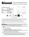
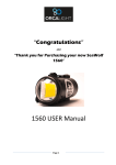
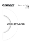
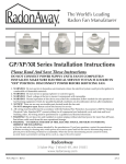
Inline Fans for a Healthier Environment RB Series Installation Instructions Spruce Environmental Technologies, Inc. 3 Saber Way Ward Hill, MA 01835 www.spruce.com P/N IN018-REV Q 8/15 RB Series Fan Installation & Operating Instructions Please Read and Save these Instructions DO NOT CONNECT POWER SUPPLY UNTIL FAN IS COMPLETELY INSTALLED. MAKE SURE ELECTRICAL SERVICE TO FAN IS LOCKED IN "OFF" POSITION. DISCONNECT POWER BEFORE SERVICING FAN. 1. 2. 3. 4. 5. 6. 7. WARNING! For General Ventilating Use Only. Do Not Use to Exhaust Hazardous, Corrosive or Explosive Materials, Gases or Vapors. See Vapor Intrusion Application Note #AN001 for important information on VI applications. RadonAway.com/vapor-intrusion NOTE: Fan is suitable for use with solid state speed controls however use of speed controls is not generally recommended. WARNING! Check voltage at the fan to insure it corresponds with nameplate. NOTICE! Normal operation of this device may affect the combustion airflow needed for safe operation of fuel burning equipment. Check for possible backdraft conditions on all combustion devices after installation. NOTICE! There are no user serviceable parts located inside the fan unit. Do NOT attempt to open. Return unit to the factory for service. WARNING! Do not leave fan unit installed on system piping without electrical power for more than 48 hours. Fan failure could result from this non-operational storage. WARNING! TO REDUCE THE RISK OF FIRE, ELECTRIC SHOCK, OR INJURY TO PERSONS, OBSERVE THE FOLLOWING: a. Use this unit only in the manner intended by the manufacturer. If you have questions, contact the manufacturer. b. Before servicing or cleaning unit, switch power off at service panel and lock the service disconnecting means to prevent power from being switched on accidentally. When the service disconnecting means cannot be locked, securely fasten a prominent warning device, such as a tag, to the service panel. c. Installation work and electrical wiring must be done by qualified person(s) in accordance with all applicable codes and standards, including fire rated construction. d. Sufficient air is needed for proper combustion and exhausting of gases through the flue (chimney) of fuel burning equipment to prevent back drafting. Follow the heating equipment manufacturers guideline and safety standards such as those published by the National Fire Protection Association, and the American Society for Heating, Refrigeration and Air Conditioning Engineers (ASHRAE), and the local code authorities. e. When cutting or drilling into a wall or ceiling, do not damage electrical wiring and other hidden utilities. f. Ducted fans must always be vented to outdoors. g. If this unit is to be installed over a tub or shower, it must be marked as appropriate for the application and be connected to a GFCI (Ground Fault Circuit Interrupter) - protected branch circuit. Page 2 of 8 IN018 Rev Q 1.0 Mounting INSTALLATION INSTRUCTIONS IN018 Rev Q RB Series RB110 p/n 23046-‐‑1, 28128 RB275 p/n 23034-‐‑1, 28115 RB300 p/n 23022-‐‑1, 28088 RB350 p/n 23023-‐‑1, 28261 RB400 p/n 23052-‐‑1, 28206 RB500 p/n 23053-‐‑1, 28207 The Spruce RB Series fans may be mounted at any angle without affecting performance although the vertical mounting position shown in Fig. 1 is highly recommended. If the vertical mounting position is not possible, care should be taken to avoid creating a low spot in the fan/duct system where condensation might accumulate in the fan housing as shown in Fig. 2. In situations where horizontal mounting is desired and condensation is likely to occur (bathroom ventilation in cold climates) this problem might be avoided by mounting the fan 30 degrees beyond horizontal as shown in Fig. 3. 2.0 Fan Sealing RB Series Fans are factory sealed, no additional caulk or other materials are required to inhibit air leakage. 3.0 Ducting Any type of ducting is acceptable, however, flexible nonmetallic ducting is recommended for easy installation and quieter operation. Insulated flexible ducting is highly recommended in cold climates to prevent the warm bathroom air from forming condensation in the ducting where it is exposed to colder attic air. The outlet of the fan should always be ducted to the outside. Avoid venting the outlet of the fan directly into an attic area. The excess moisture from the bathroom can cause damage to building structure and any items stored in the attic. Multiple venting points may be connected together using a "ʺT"ʺ or "ʺY"ʺ fitting. Ideally Duct should be arranged such that equal duct lengths are used between intake and "ʺT"ʺ or "ʺY"ʺ fitting, this will result in equal flow rates in each intake branch. If adjustable intake grilles are used on multi-‐‑intake systems then the opening on each grill should be equal in order to minimize noise and resistance. Straight smooth runs of rigid metal ducting will present the least resistance and maximize system performance. The Equivalent Length of Rigid Metal Ducting resulting in .2” WC pressure loss for each Fan Model is provided in the specification section of these Instructions. Flexible ducting, if used, must always be as close to being fully extended as possible. Formed rigid metal duct elbows will present the least resistance and maximize system performance, recommended bend radius of elbow is at least 1.5 x duct diameter. To ensure quiet operation of ENERGY STAR qualified in-‐‑line and remote fans, each fan shall be installed using sound attenuation techniques appropriate for the installation. For bathroom and general ventilation applications, at least 8 feet of insulated flexible duct shall be installed between the exhaust or supply grille(s) and the fan. RB Series fans are not suitable for kitchen range hood remote ventilation applications. The ducting from this fan to the outside of the building has a strong effect on the airflow, noise and energy use of the fan. Use the shortest, straightest duct routing possible for best performance, and avoid installing the fan with smaller ducts than recommended. Insulation around the ducts can reduce energy loss and inhibit mold growth. Fans installed with existing ducts may not achieve their rated airflow. Page 3 of 8 IN018 Rev Q 4.0 Back Draft Dampers Back draft dampers allow airflow in only one direction preventing cold/hot drafts from entering the vented area and minimize possible condensation and icing within the system while the fan is not operating. Back draft dampers are highly recommended at each intake grille for bathroom ventilation in all cold climate installations. Installation instructions are included with Spruce back dra0 dampers. 5.0 Electrical Wiring All wiring must be performed in accordance with the National Fire Protection Association’s (NFPA)”National Electrical Code, Standard #70”-‐‑current edition for all commercial and industrial work, and state and local building codes. All wiring must be performed by a qualified and licensed electrician. A Ground Fault Interrupter (GFI) circuit is not required in most installations, check your local codes. Ensure that all exterior electrical boxes are outdoor rated and properly sealed to prevent water penetration into the box. A means, such as a weep hole, is recommended to drain the box. Note that the fan is not intended for connection to rigid metal conduit. 6.0 Applications Suitable for general ventilation, bathroom venting, fresh air supply, duct boosting, building pressurization, etc. Not suitable for kitchen range hood venting. Page 4 of 8 IN018 Rev Q Fig. 4 7.0 Installation Step 1: Install Mounting Bracket as shown (Fig. 4) (RB110 & RB 275 Only, separate instructions for RB400 & RB500 are included with Mounting Bracket Kit). Insert Grommets into slots in mounting bracket. Orientate the Electrical Box relative to Mounting Bracket as required. A1ach the fan to the mounting bracket with (3) #10 self-‐‑tapping screws, provided. Avoid over tightening screws. Step 2: Select location for fan mounting. A location 2/3 along the ducting, a minimum of 10 feet away from the inlet vent to the fan or the Y/T of a multi-‐‑intake system will provide the quietest operation. Fan should be mounted vertically to prevent moisture from accumulating in the fan housing. A1ach bracket to mounting structure with the 1 1/4” screws provided (Fig. 5). Step 3: Connect ductwork between fan inlet and area to be vented through inlet grille (Fig. 6). Flexible, nonmetallic ducting is recommended for quietest operation and easiest installation. Insulated flexible ducting is highly recommended for bathroom ventilation in all cold climate installations. Metal worm drive clamps, spring clamps, adjustable plastic ratchets are recommended for connection of ducting. Silicon Caulk or Duct Tape may be used for additional sealing. Duct Tape should be used to retain insulation. Step 4: Connect inlet grille(s) (Fig. 7). An optional back draft damper may be installed in the inlet grille to prevent cold air from backing into the inlet, prevent conditioned air from escaping and also prevent condensation from forming inside the ductwork. Backdraft dampers are highly recommended at each intake grille for bathroom ventilation in all cold climate installations. Step 5: Connect outlet of fan to outside vent (Fig. 8). The outside vent may go through the roof, sidewall or soffit as desired. Flexible, nonmetallic ducting is recommended for quietest operation and easiest installation. Insulated flexible ducting is highly recommended for bathroom ventilation in all cold climate installations. Step 6: Make electrical connection to fan (Fig. 9). Insure any metal fi1ing used in the installation is properly grounded. A plastic cable connector such as a T&B #3300 may be used to avoid any fi1ing grounding problem. Observe the proper wiring connections (See Section 5.0). Note that the fan is not intended for connection to rigid metal conduit. RB Series Wire AC Connection Black AC Line White AC Common Green or Grn/Ye Ground Fig. 5 Fig. 6 Fig. 7 Fig. 8 Fig. 9 Page 5 of 8 IN018 Rev Q RB SERIES PRODUCT SPECIFICATIONS The following chart shows fan performance for RB Series Commercial/Residential Fans: Typical CFM vs. Static Pressure “WC 0” .2” .5” .75” 1.0” 1.25” 1.5” 1.75” 2.0” RB110 121 100 68 20 -‐‑ -‐‑ -‐‑ -‐‑ -‐‑ RB275 272 230 176 138 103 57 13 -‐‑ -‐‑ RB300 318 270 211 170 135 87 30 -‐‑ -‐‑ RB350 334 300 247 210 176 142 116 87 52 RB400 497 450 353 281 220 176 128 79 38 RB500 542 500 420 344 275 219 165 102 48 Power Consumption @ 120 VAC, 60Hz (2.0 Amp Maximum) RB110 RB275 RB300 RB350 RB400 RB500 14-‐‑19 watts 50-‐‑75 watts 66-‐‑87 watts 91-‐‑129 watts 95-‐‑152 watts 99-‐‑152 watts Size Chart Fan Model RB110 RB275 RB300 RB350 RB400 RB500 “A” Dim “B” Dim “C” Dim Duct Size Weight L.2 9.7” 11.8” 13.4” 13.4” 13.4” 13.4” 3.9” 5.9” 5.9” 5.9” 7.9” 9.9” 8.5” 8.6” 9” 9” 10.5” 10.5” 4” 6” 6” 6” 8” 10” 5 lbs 5.5 lbs 8 lbs 8.5 lbs 11.5 lbs 11.5 lbs 30ft 48 ft 40 ft 30 ft 57 ft 140 ft L.2 = Estimated Equivalent Length of Rigid Metal Ducting resulting in .2in WC pressure loss for Duct Size listed. Longer Equivalent Lengths can be accommodated at Flows Lower than that at .2in WC pressure loss (see CFM Vs Static Pressure “WC Table). Do not operate fan above 80% of maximum Static Pressure per performance table. Mounting: Mounting bracket included. Recommended Ducting: 4”, 6”, 8” or 10” Rigid or Flexible Ducting Storage Temperature Range: 32 -‐‑ 100 degrees F. Normal Operating Temperature Range: -‐‑20 -‐‑ 120degrees F. Maximum Inlet Air Temperature: 140 degrees F continuous Continuous Duty: 3000 RPM Thermally Protected: Class F Insulation [RB110 Class B] Rated for Indoor use only Rated for Residential and Commercial use Suitable for use with solid-‐‑state speed controls Suitable for use over tub or shower Page 6 of 8 IN018 Rev Q Page 7 of 8 -RB110 - P/N 28128 -RB275 - P/N 28115 -RB300 - P/N 28088 -RB350 - P/N 28261 -RB400 - P/N 28206 -RB500 - P/N 28207 IN018 Rev Q IMPORTANT INSTRUCTIONS TO INSTALLER Inspect the RB Series Fan for shipping damage within 15 days of receipt. Notify Spruce of any damages immediately. Spruce is not responsible for damages incurred during shipping. However, for your benefit, Spruce does insure shipments. There are no user serviceable parts inside the fan. Do not attempt to open. Return unit to factory for service. Install the RB Series Fan in accordance with all state and local building codes and state regulations. WARRANTY Subject to any applicable consumer protection legislation, Spruce Environmental Technologies Inc. (“Spruce”) warrants that the RB Series Fan (the “Fan”) will be free from defects in materials and workmanship for a period of five (5) years from the date of manufacture (the “Warranty Term”). Warranty claims made during the first thirty days after installation: Spruce will replace any Fan which fails due to defects in materials or workmanship. The Fan may be returned (at owner’s cost) to either the point of purchase or the Spruce factory. The point of purchase may require proof of purchase or a bill of sales for replacement. Warranty claims made after the first thirty days after installation through the end of the Warranty Term: Spruce will (at its option) either recondition or replace any Fan which fails due to defects in materials or workmanship. The Fan must be returned (at owner’s cost) to the Spruce factory. This Warranty is contingent on installation of the Fan in accordance with the instructions provided. This Warranty does not apply where any repairs or alterations have been made or a1empted by others, or if the unit has been abused or misused. Warranty does not include damage in shipment unless the damage is due to the negligence of Spruce. Spruce is not responsible for installation, removal or delivery costs associated with this Warranty. EXCEPT AS STATED ABOVE, THE RB SERIES FANS ARE PROVIDED WITHOUT WARRANTY OF ANY KIND, EITHER EXPRESS OR IMPLIED, INCLUDING, WITHOUT LIMITATION, IMPLIED WARRANTIES OF MERCHANTABILITY AND FITNESS FOR A PARTICULAR PURPOSE. IN NO EVENT SHALL SPRUCE BE LIABLE FOR ANY DIRECT, INDIRECT, SPECIAL, INCIDENTAL, OR CONSEQUENTIAL DAMAGES ARISING OUT OF, OR RELATING TO, THE FAN OR THE PERFORMANCE THEREOF. SPRUCE’S AGGREGATE LIABILITY HEREUNDER SHALL NOT IN ANY EVENT EXCEED THE AMOUNT OF THE PURCHASE PRICE OF SAID PRODUCT. THE SOLE AND EXCLUSIVE REMEDY UNDER THIS WARRANTY SHALL BE THE REPAIR OR REPLACEMENT OF THE PRODUCT, TO THE EXTENT THE SAME DOES NOT MEET WITH SPRUCE’S WARRANTY AS PROVIDED ABOVE. For service under this Warranty, contact Spruce for a Return Material Authorization (RMA) number and shipping information. No returns can be accepted without an RMA. If factory return is required, the customer assumes all shipping cost to and from factory. Spruce Environmental Technologies, Inc. 3 Saber Way Ward Hill, MA 01835 TEL. (978) 521-‐‑0901 FAX (978) 521-‐‑3964 Record the following information for your records: Serial No. Purchase Date Page 8 of 8 IN018 Rev Q P