1
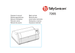
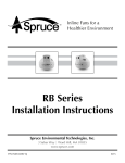
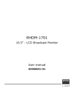
The World’s Leading
Radon Fan Manufacturer
RP Series
Installation & Operating
Instructions
RadonAway
3 Saber Way Ward Hill, MA 01835
www.radonaway.com
P/N IN020-REV R
08/15
DO NOT CONNECT POWER SUPPLY UNTIL FAN IS COMPLETELY INSTALLED.
MAKE SURE ELECTRICAL SERVICE TO FAN IS LOCKED IN "OFF" POSITION.
DISCONNECT POWER BEFORE SERVICING FAN.
1.
2.
3.
4.
5.
WARNING!
WARNING! For General Ventilating Use Only. Do Not Use to Exhaust Hazardous, Corrosive or
Explosive Materials, Gases or Vapors. See Vapor Intrusion Application Note #AN001 for important information on VI
applications. RadonAway.com/vapor-intrusion
WARNING! NOTE: Fan is suitable for use with solid state speed controls however use of speed controls is not
generally recommended.
WARNING! Check voltage at the fan to insure it corresponds with nameplate.
WARNING!
Normal operation of this device may affect the combustion airflow needed for safe operation of fuel
burning equipment. Check for possible backdraft conditions on all combustion devices after installation.
NOTICE!
There are no user serviceable parts located inside the fan unit.
Do NOT attempt to open. Return unit to the factory for service.
6.
WARNING! Do not leave fan unit installed on system piping without electrical power for more than 48 hours. Fan
failure could result from this non-operational storage.
7.
WARNING! TO REDUCE THE RISK OF FIRE, ELECTRIC SHOCK, OR INJURY TO PERSONS, OBSERVE THE
FOLLOWING:
a) Use this unit only in the manner intended by the manufacturer. If you have questions, contact the manufacturer.
b) Before servicing or cleaning unit, switch power off at service panel and lock the service disconnecting means to
prevent power from being switched on accidentally. When the service disconnecting means cannot be locked, securely
fasten a prominent warning device, such as a tag, to the service panel.
c) Installation work and electrical wiring must be done by qualified person(s) in accordance with all applicable codes
and standards, including fire rated construction.
d) Sufficient air is needed for proper combustion and exhausting of gases through the flue (chimney) of fuel burning
equipment to prevent back drafting. Follow the heating equipment manufacturers guideline and safety standards
such as those published by the National Fire Protection Association, and the American Society for Heating,
Refrigeration and Air Conditioning Engineers (ASHRAE), and the local code authorities.
e) When cutting or drilling into a wall or ceiling, do not damage electrical wiring and other hidden utilities.
f) Ducted fans must always be vented to outdoors.
g) If this unit is to be installed over a tub or shower, it must be marked as appropriate for the application and be
connected to a GFCI (Ground Fault Circuit Interrupter) - protected branch circuit.
INSTALLATION & OPERATING INSTRUCTIONS IN020 Rev R
RP Series
RP140
RP145
RP260
RP265
RP380
p/n 23029-1
p/n 23030-1
p/n 23032-1
p/n 23033-1
p/n 28208
1.0 SYSTEM DESIGN CONSIDERATIONS
1.1. INTRODUCTION
The RP Series Radon Fans are intended for use by trained, professional, certified/licensed Radon mitigators. The
purpose of this instruction is to provide additional guidance for the most effective use of an RP Series Fan.
This instruction should be considered as a supplement to EPA/radon industry standard practices, state and
local building codes and state regulations. In the event of a conflict, those codes, practices and regulations
take precedence over this instruction.
1.2. FAN SEALING
The RP Series Fans are factory sealed, no additional caulk or other materials are required to inhibit air leakage.
1.3.
ENVIRONMENTALS
The RP Series Fans are designed to perform year-round in all but the harshest climates without additional
concern for temperature or weather. For installations in an area of severe cold weather, please contact
RadonAway for assistance. When not in operation, the fan should be stored in an area where the temperature
is never less than 32 degrees F. or more than 100 degrees F.
1.4. ACOUSTICS
The RP Series Fan, when installed properly, operates with little or no noticeable noise to the building
occupants. The velocity of the outgoing air should be considered in the overall system design. In some cases the
"rushing" sound of the outlet air may be disturbing. In these instances, the use of a RadonAway Exhaust
Muffler is recommended.
(To ensure quiet operation of ENERGY STAR qualified in-line and remote fans, each fan shall be installed using sound attenuation techniques appropriate for the
installation. For bathroom and general ventilation applications, at least 8 feet of insulated flexible duct shall be installed between the exhaust or supply grille(s) and the fan).
RP Series fans are not suitable for kitchen range hood remote ventilation applications.
1.5. GROUND WATER
In the event that a temporary high water table results in water at or above slab level, water may be drawn
into the riser pipes thus blocking air flow to the RP Series Fan. The lack of cooling air may result in the fan
cycling on and off as the internal temperature rises above the thermal cutoff and falls upon shutoff. Should
this condition arise, it is recommended that the fan be turned off until the water recedes allowing for return to
normal operation.
1.6. SLAB COVERAGE
The RP Series Fan can provide coverage up to 2000+ sq. ft. per slab penetration. This will primarily depend
on the sub-slab material in any particular installation. In general, the tighter the material, the smaller the area
covered per penetration. Appropriate selection of the RP Series Fan best suited for the sub-slab material can
improve the slab coverage. The RP140/145/155 are best suited for general purpose use. The RP260 can be used
where additional airflow is required and the RP265/380 is best suited for large slab, high airflow applications.
Additional suction points can be added as required. It is recommended that a small pit (5 to 10 gallons in size) be
created below the slab at each suction hole.
1.7. CONDENSATION & DRAINAGE
Condensation is formed in the piping of a mitigation system when the air in the piping is chilled below its dew
point. This can occur at points where the system piping goes through unheated space such as an attic, garage or
outside. The system design must provide a means for water to drain back to a slab hole to remove the condensation.
The RP Series Fan MUST be mounted vertically plumb and level, with the outlet pointing up for proper drainage
through the fan. Avoid mounting the fan in any orientation that will allow water to accumulate inside the fan
housing. The RP Series Fans are NOT suitable for underground burial.
For RP Series Fan piping, the following table provides the minimum recommended pipe diameter and pitch
under several system conditions.
@25 CFM
@50 CFM
@100 CFM
@200 CFM
@300 CFM
6"
-
3/16
1/4
3/8
3/4
4"
1/8
1/4
3/8
2 3/8
-
3"
1/4
3/8
1 1/2
-
-
RISE
RUN
*Typical RP1xx/2xx Series Fan operational flow rate is 25 - 90 CFM 0n 3” and 4” pipe. (For more precision, determine flow rate by
measuring Static Pressure, in WC, and correlate pressure to flow in the performance chart in the addendum.)
Under some circumstances in an outdoor installation a
condensate bypass should be installed in the outlet ducting as
shown. This may be particularly true in cold climate installations
which require long lengths of outlet ducting or where the outlet
ducting is likely to produce large amounts of condensation
because of high soil moisture or outlet duct material. Schedule
20 piping and other thin-walled plastic ducting and Aluminum
downspout will normally produce much more condensation
than Schedule 40 piping. Schedule 40 piping is preferred for
radon mitigation, all joints should fully sealed using the
appropriate pipe cement on socket type fittings or flexible
coupling firmly attached via worm drive screw clamps. Sealing
ducting or pipe with duct tape is not acceptable on radon
mitigation installations. No pipe penetrations are permitted,
other than the condensation bypass. Silicon caulk is permitted
for sealing purposes.
The bypass is constructed with a 45 degree Wye fitting at
the bottom of the outlet stack. The bottom of the Wye is
capped and fitted with a tube that connects to the inlet
piping or other drain. The condensation produced in the
outlet stack is collected in the Wye fitting and drained
through the bypass tube. The bypass tubing may be insulated
to prevent freezing.
1.8. SYSTEM MONITOR & LABEL
A System Monitor, such as a manometer (P/N 50017) or
audible alarm (P/N 28001-2) is required to notify the
occupants of a fan system malfunction. A System Label
(provided with Manometer P/N 50017) with instructions for
contacting the installing contractor for service and also
identifying the necessity for regular radon tests to be
conducted by the building occupants, must be conspicuously
placed where the occupants frequent and can see the label.
1.9. VENTILATION
If used as a ventilation Fan any type of ducting is acceptable, however, flexible nonmetallic ducting is recommended for
easy installation and quieter operation. Insulated flexible ducting is highly recommended in cold climates to prevent
the warm bathroom air from forming condensation in the ducting where it is exposed to colder attic air. The outlet of
the fan should always be ducted to the outside. Avoid venting the outlet of the fan directly into an attic area. The excess
moisture from the bathroom can cause damage to building structure and any items stored in the attic. Multiple venting
points may be connected together using a "T" or "Y" fitting. Ideally Duct should be arranged such that equal duct
lengths are used between intake and "T" or "Y" fitting, this will result in equal flow rates in each intake branch. If
adjustable intake grilles are used on multi-intake systems then the opening on each grill should be equal in order to
minimize noise and resistance. Straight smooth runs of rigid metal ducting will present the least resistance and
maximize system performance. The Equivalent Length of Rigid Metal Ducting resulting in .2” WC pressure loss for
each Fan Model is provided in the specification section of these Instructions. Flexible ducting, if used, must always be
as close to being fully extended as possible. Formed rigid metal duct elbows will present the least resistance and
maximize system performance, recommended bend radius of elbow is at least 1.5 x duct diameter.
RP Series fans are not suitable for kitchen range hood remote ventilation applications. For quietest performance, the
fan should be mounted further away from the inlet duct, near the outside vent. A minimum distance of 8 feet is
recommended between the fan or T/Y of a multi-intake system and intake grille(s).
Backdraft dampers allow airflow in only one direction preventing cold/hot drafts from entering the vented area and
minimize possible condensation and icing within the system while the fan is not operating. Backdraft dampers are
highly recommended at each intake grille for bathroom ventilation in all cold climate installations. Installation
instructions are included with Spruce back draft dampers.
The ducting from this fan to the outside of the building has a strong effect on the airflow, noise and energy use of the
fan. Use the shortest, straightest duct routing possible for best performance, and avoid installing the fan with smaller
ducts than recommended. Insulation around the ducts can reduce energy loss and inhibit mold growth. Fans installed
with existing ducts may not achieve their rated airflow.
1.10. ELECTRICAL WIRING
The RP Series Fans operate on standard 120V 60 Hz. AC. All wiring must be performed in accordance
with the National Fire Protection Association’s (NFPA)”National Electrical Code, Standard #70”-current
edition for all commercial and industrial work, and state and local building codes. All wiring must be
performed by a qualified and licensed electrician. Outdoor installations require the use of a U.L. listed
watertight conduit. Ensure that all exterior electrical boxes are outdoor rated and properly sealed to
prevent water penetration into the box. A means, such as a weep hole, is recommended to drain the box.
1.11. SPEED CONTROLS
The RP Series Fans are rated for use with electronic speed controls, however, they are generally not
recommended. If used, the recommended speed control is Pass & Seymour Solid State Speed Control
Cat. No. 94601-I.
2.0 INSTALLATION
The RP Series Fan can be mounted indoors or outdoors. (It is
suggested that EPA recommendations be followed in choosing
the fan location.) The RP Series Fan may be mounted directly
on the system piping or fastened to a supporting structure by
means of optional mounting bracket
2.1 MOUNTING
Mount the RP Series Fan vertically with outlet up. Insure
the unit is plumb and level. When mounting directly on the
system piping assure that the fan does not contact any
building surface to avoid vibration noise.
2.2 MOUNTING BRACKET (optional)
The RP Series Fan may be optionally secured with the RadonAway
P/N 25007 (25033 for RP385) mounting bracket. Foam or rubber
grommets may also be used between the bracket and mounting
surface for vibration isolation.
2.3 SYSTEM PIPING
Complete piping run, using flexible couplings as means of
disconnect for servicing the unit and vibration isolation. Used as a
Radon Fan the fan is typically outside of the building thermal
boundary, and is venting to the outside, installation of insulation
around the fan is not required. If used as a ventilation fan insulation
may be installed around the fan and duct work, insulation should be
sized appropriately for the duct size used and secured with duct
tape.
2.4 ELECTRICAL CONNECTION
Connect wiring with wire nuts provided, observing proper
connections (See Section 1.10). Note that the fan is not intended
for connection to rigid metal conduit.
Fan Wire
Green
Black
White
Connection
Ground
AC Hot
AC Common
2.5 VENT MUFFLER (optional)
Install the muffler assembly in the selected location in the outlet ducting. Solvent weld all
connections. The muffler is normally installed at the end of the vent pipe.
2.6 OPERATION CHECKS & ANNUAL SYSTEM MAINTENANCE
Verify all connections are tight and leak-free.
Insure the RP Series Fan and all ducting is secure and vibration-free.
Verify system vacuum pressure with manometer. Insure vacuum pressure is within normal
operating range and less than the maximum recommended operating pressure.
(Based on sea-level operation, at higher altitudes reduce by about 4% per 1000 Feet.)
(Further reduce Maximum Operating Pressure by 10% for High Temperature environments)
See Product Specifications. If this is exceeded, increase the number of suction points.
Verify Radon levels by testing to EPA protocol.
RP SERIES PRODUCT SPECIFICATIONS
The following chart shows fan performance for the RP Series Fan:
Typical CFM Vs Static Pressure "WC
0"
.25"
.5"
135
103
70
RP140
RP145
166
146
126
RP260
272
220
176
RP265
334
291
247
RP380*
497
401
353
* Tested with 6” inlet and discharge pipe.
Power Consumption
120 VAC, 60Hz 1.5 Amp Maximum
RP140
17 - 21
watts
RP145
41 - 72
watts
RP260
52 - 72
watts
RP265
91 - 129
watts
RP380
95 - 152
watts
.75"
14
104
138
210
281
1.0"
82
103
176
220
1.25"
61
57
142
176
1.5"
41
13
116
130
1.75"
21
87
80
2.0"
3
52
38
Maximum Recommended
Operating Pressure* (Sea Level Operation)**
RP140
0.8" W.C.
RP145
1.7" W.C.
RP260
1.5" W.C.
RP265
2.2" W.C.
RP380
2.0" W.C.
*Reduce by 10% for High Temperature Operation
**Reduce by 4% per 1000 feet of altitude
RP140
Size
8.5H" x 9.7" Dia.
Weight
5.5 lbs.
Inlet/Outlet
4.5" OD (4.0" PVC Sched 40 size compatible)
L.2
25
RP145
RP260
RP265
RP380
8.5H" x 9.7" Dia.
8.6H" x 11.75" Dia.
8.6H" x 11.75" Dia.
10.53H" x 13.41" Dia.
5.5 lbs.
5.5 lbs.
6.5 lbs.
11.5 lbs.
4.5" OD (4.0" PVC Sched 40 size compatible)
6.0” OD
6.0” OD
8.0” OD
15
48
30
57
L.2 = Estimated Equivalent Length of Rigid Metal Ducting resulting in .2in WC pressure loss for Duct Size listed. Longer Equivalent Lengths
can be accommodated at Flows Lower than that at .2in WC pressure loss (see CFM Vs Static Pressure "WC Table).
Recommended ducting: 3" or 4" RP1xx/2xx, 6” RP380, Schedule 20/40 PVC Pipe
Mounting: If used for Ventilation use 4", 6" or 8" Rigid or Flexible Ducting
Mount on the duct pipe or with optional mounting bracket.
Storage temperature range: 32 - 100 degrees F.
Normal operating temperature range: -20 - 120 degrees F.
Maximum inlet air temperature: 80 degrees F.
Continuous Duty
Class F Insulation [RP140 Class B]
Class B Insulation
Thermally Protected
3000 RPM
Rated for Indoor or Outdoor Use
IMPORTANT INSTRUCTIONS TO INSTALLER
Inspect the GP/XP/XR/RP/SF Series Fan for shipping damage within 15 days of receipt. Notify
RadonAway® of any damages immediately. RadonAway® is not responsible for damages incurred during
shipping. However, for your benefit, RadonAway® does insure shipments.
There are no user serviceable parts inside the fan. Do not attempt to open. Return unit to factory for service.
Install the GP/XP/XR/RP/SF Series Fan in accordance with all EPA standard practices, and state and local
building codes and state regulations.
Provide a copy of this instruction or comparable radon system and testing information to the building
occupants after completing system installation.
WARRANTY
RadonAway® warrants that the GPX01/XP/XR/RP/SF Series Fan (the “Fan”) will be free from defects in materials and workmanship for a
period of 90 days from the date of purchase (the “Warranty Term”).
RadonAway® will replace any Fan which fails due to defects in materials or workmanship during the Warranty Term. The Fan must be
returned (at Owner’s cost) to the RadonAway® factory. Any Fan returned to the factory will be discarded unless the Owner provides specific
instructions along with the Fan when it is returned regardless of whether or not the Fan is actually replaced under this warranty. Proof of
purchase must be supplied upon request for service under this Warranty.
This Warranty is contingent on installation of the Fan in accordance with the instructions provided. This Warranty does not apply where any
repairs or alterations have been made or attempted by others, or if the unit has been abused or misused. Warranty does not cover damage
in shipment unless the damage is due to the negligence of RadonAway®.
5 YEAR EXTENDED WARRANTY WITH PROFESSIONAL INSTALLATION.
RadonAway® will extend the Warranty Term of the fan to five (5) years from date of purchase or sixty-three (63) months from the date of
manufacture, whichever is sooner, if the Fan is installed in a professionally designed and professionally installed active soil depressurization
system or installed as a replacement fan in a professionally designed and professionally installed active soil depressurization system by a
qualified installer. Proof of purchase and/or proof of professional installation may be required for service under this warranty. Outside the
Continental United States and Canada the extended Warranty Term is limited to one (1) year from the date of manufacture.
RadonAway® is not responsible for installation, removal or delivery costs associated with this Warranty.
LIMITATION OF WARRANTY
EXCEPT AS STATED ABOVE, THE GPx01/XP/XR/RP SERIES FANS ARE PROVIDED WITHOUT WARRANTY OF ANY KIND, EITHER
EXPRESS OR IMPLIED, INCLUDING, WITHOUT LIMITATION, IMPLIED WARRANTIES OF MERCHANTABILITY AND FITNESS FOR A
PARTICULAR PURPOSE.
IN NO EVENT SHALL RADONAWAY BE LIABLE FOR ANY DIRECT, INDIRECT, SPECIAL, INCIDENTAL, OR CONSEQUENTIAL
DAMAGES ARISING OUT OF, OR RELATING TO, THE FAN OR THE PERFORMANCE THEREOF. RADONAWAY’S AGGREGATE
LIABILITY HEREUNDER SHALL NOT IN ANY EVENT EXCEED THE AMOUNT OF THE PURCHASE PRICE OF SAID PRODUCT. THE
SOLE AND EXCLUSIVE REMEDY UNDER THIS WARRANTY SHALL BE THE REPAIR OR REPLACEMENT OF THE PRODUCT, TO
THE EXTENT THE SAME DOES NOT MEET WITH RADONAWAY’S WARRANTY AS PROVIDED ABOVE.
For service under this Warranty, contact RadonAway for a Return Material Authorization (RMA) number and shipping information. No returns
can be accepted without an RMA. If factory return is required, the customer assumes all shipping costs, including insurance, to and from
factory.
RadonAway® 3 Saber Way
Ward Hill, MA 01835 USA TEL (978) 521-3703
FAX (978) 521-3964
Email to: [email protected]
Record the following information for your records:
Serial No.
Purchase Date