1
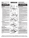
11. Insert outer housing through hole on outside wall
and nail or screw housing to casing strips. Caulk
all around filler strips and flange. (FIG. 9)
12. Run wiring to fan location. Pull wire through both
sleeves. (FIG. 10) Insert inner sleeve into opening
and fasten sleeves together with three black sheet
metal screws provided in plastic bag.
13. Attach wiring to wiring box with proper connector
for type of wire being used. Drop box into opening
in housing.
14. 509S, 509SMX ONLY! Insert switch into wiring box
and fasten with nut provided. (FIG. 11)
15. Make electrical connections as shown in Figures
12 and 12A. Make sure unit is grounded using
green ground screw.
16. Install wiring box cover. Use two screws provided
in plastic bag.
17. Reinstall motor assembly and plug in motor.
18. Fasten grille to motor bracket with knob and stud
from parts bag. 509S, 509SMX ONLY: Attach knob
to rotary switch. (FIG. 13)
11. Meta la caja exterior a través del agujero en la pared
exterior y clave o atornille la caja a las tiras del
contramarco. Selle con masilla de sellar alrededor de
las tiras de llenado y el borde. (FIG. 9)
12. Lleve el cableado adonde se instala el ventilador. Tire
del cable a través de las dos cubiertas. (FIG. 10) Meta
la cubierta interior en la abertura y fije las dos cubiertas
con tres tornillos de lámina de metal negros que se
incluyen en la bolsa de plástico.
13. Fije el cableado a la caja de cables con el conector
apropiado para el tipo de cable que se está usando.
Coloque la caja de cables dentro de la caja principal.
14. SOLAMENTE PARA EL MODELO 509S, 509SMX:
Meta el interruptor en la caja de cables y fíjelo con la
tuerca que se suministra. (FIG. 11)
15. Haga las conexiones eléctricas tal como se muestra
en las figuras 12 y 12A. Asegúrese de que la unidad
está conectada a tierra con el tornillo verde de tierra.
16. Instale la cubierta de la caja de cables. Utilice los dos
tornillos que se suministran en la bolsa de plástico.
17. Vuelva a instalar el conjunto del motor y conecte el
motor.
18. Sujete la rejilla al soporte del motor con perilla y tornillo
de la rejilla en la bolsa de piezas. SOLAMENTE PARA
EL MODELO 509S, 509SMX: Fije la perilla al
interruptor giratorio. (FIG. 13)
FIG. 9
FIG. 10
SLEEVE
SCREW
(3 REQ.)
TORNILLO
DE FUNDA
FIG. 11
ROTARY
SWITCH
INTERRUPTOR
GIRATORIO
SWITCH
NUT
TUERCA DEL
INTERRUPTOR
FIG. 12
WIRING BOX
COVER
CUBIERTA DE
LA CAJA DE
CABLES
WHITE
BLANCO
BLACK
NEGRO
GROUND (BARE OR GREEN WHITE)
TIERRA (CABLE VERDE O DESCUBIERTO)
FIG. 12A
BLACK
NEGRO
509S,
509SMX
WHITE
BLANCO
ROTARY SWITCH
GROUND (BARE OR GREEN WHITE)
INTERRUPTOR
TIERRA (CABLE VERDE O DESCUBIERTO) GIRATORIO
FIG. 13
KNOB
(509S, 509SMX ONLY)
PERILLA (SOLAMENTE EN EL MODELO 509S, 509SMX)
3