1
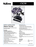
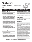
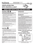
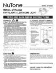
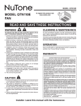
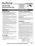
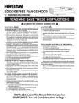
MODEL 744FLNT
RECESSED
FLUORESCENT FAN / LIGHT
Page 1
READ AND SAVE THESE INSTRUCTIONS
WARNING
OPERATION
TO REDUCE THE RISK OF FIRE, ELECTRIC SHOCK, OR INJURY TO PERSONS, OBSERVE THE FOLLOWING:
1. Use this unit only in the manner intended by the manufacturer.
If you have questions, contact the manufacturer at the address
or telephone number listed in the warranty.
2. Before servicing or cleaning unit, switch power off at service
panel and lock the service disconnecting means to prevent
power from being switched on accidentally. When the service
disconnecting means cannot be locked, securely fasten a
prominent warning device, such as a tag, to the service panel.
3. Installation work and electrical wiring must be done by a
qualified person(s) in accordance with all applicable codes
and standards, including fire-rated construction codes and
standards.
4. Sufficient air is needed for proper combustion and exhausting
of gases through the flue (chimney) of fuel burning equipment to prevent backdrafting. Follow the heating equipment
manufacturer’s guideline and safety standards such as those
published by the National Fire Protection Association (NFPA),
and the American Society for Heating, Refrigeration and Air
Conditioning Engineers (ASHRAE), and the local code authorities.
5. When cutting or drilling into wall or ceiling, do not damage
electrical wiring and other hidden utilities.
6. Ducted fans must always be vented to the outdoors.
7. Never place a switch where it can be reached from a tub or
shower.
8. Do not use a dimmer switch to operate the light in this unit.
9. Install this unit in a flat ceiling only.
10. For use in non fire rated installations only.
11. Not for use in environmental air handling spaces.
12. If this unit is to be installed over a tub or shower, it must be
marked as appropriate for the application and be connected
to a GFCI (Ground Fault Circuit Interrupter) - protected branch
circuit.
13. Do not install in a ceiling thermally insulated to a value greater
than R40.
14. This unit must be grounded.
CAUTION
!
1. For general ventilating use only. Do not use to exhaust
hazardous or explosive materials and vapors.
2. To avoid motor bearing damage and noisy and/or unbalanced
impellers, use the cardboard protector (provided) to keep
drywall spray, construction dust, etc. off power unit.
3. The fluorescent bulb used with this product twists into the bulb
socket. Do not attempt to insert or remove bulb by pushing
it straight in or pulling it straight down.
4. Please read specification label on product for further
information and requirements.
The fan and light can be operated using various combinations of
on/off switches and controls:
•
•
•
•
Fanandlightcontrolledwithsingleon/offswitch
Fanandlightcontrolledwithseparateon/offswitches
Fancontrolledwithtimercontrol
Fancontrolledwithspeedcontrol
See “Connect Wiring” section for various wiring options.
CLEANING
To clean trim ring / baffle: Vacuum with a soft brush attachment
or remove trim ring / baffle and clean with a soft cloth and mild
soap or detergent. Dry thoroughly before reinstalling.
To clean inside of housing: Remove trim ring / baffle and
vacuum inside of housing with a soft brush attachment.
MAINTENANCE
Motor is permanently lubricated. Do not oil or disassemble motor.
See “Service Parts” section for a list and illustrations of service parts.
WARRANTY
NuTone Ventilation Fan/Lights - Limited Warranty
WARRANTY PERIOD: NuTone warrants to the original consumer purchaser of its NuTone Ventilation
Fan/light (the “Fan”) that your Fan (excluding lamps/bulbs) will be materially free from defects in
materials or workmanship for a period of three (3) years from the date of original purchase. The
warranty on the lamps/bulbs provided with the Fan is one (1) year and does not cover lamp/bulb
breakage. This warranty does not cover accessories, such as speed controls, that may be purchased
separately and installed with the Fan.
The limited warranty period for replacement parts, and for Fans repaired or replaced under this limited
warranty, shall continue for the remainder of the original warranty period.
THERE ARE NO OTHER WARRANTIES, EXPRESS OR IMPLIED, INCLUDING, BUT NOT LIMITED
TO, IMPLIED WARRANTIES OF MERCHANTABILITY OR FITNESS FOR A PARTICULAR PURPOSE.
During this one-year period, Broan-NuTone will, at its option, repair or replace, without charge, any
product or part which is found to be defective under normal use and service.
THIS WARRANTY DOES NOT EXTEND TO FLUORESCENT LAMP STARTERS AND TUBES. This warranty
does not cover (a) normal maintenance and service or (b) any products or parts which have been subject
to misuse, negligence, accident, improper maintenance or repair (other than by Broan-NuTone), faulty
installation or installation contrary to recommended installation instructions.
The duration of an implied warranty is limited to the one-year period as specified for the express
warranty. Some states do not allow limitation on how long an implied warranty lasts, so the above
limitation may not apply to you.
BROAN-NUTONE’S OBLIGATION TO REPAIR OR REPLACE, AT BROAN-NUTONE’S OPTION, SHALL
BE THE PURCHASER’S SOLE AND EXCLUSIVE REMEDY UNDER THIS WARRANTY. BROAN-NUTONE
SHALL NOT BE LIABLE FOR INCIDENTAL, CONSEQUENTIAL OR SPECIAL DAMAGES ARISING OUT OF
OR IN CONNECTION WITH PRODUCT USE OR PERFORMANCE. Some states do not allow the exclusion
or limitation of incidental or consequential damages, so the above limitation may not apply to you.
This warranty gives you specific legal rights, and you may also have other rights, which vary from state
to state. This warranty supersedes all prior warranties.
To qualify for warranty service, you must (a) notify Broan-NuTone at the address or telephone number
stated below, (b) give the model number and part identification and (c) describe the nature of any
defect in the product or part. At the time of requesting warranty service, you must present evidence
of the original purchase date.
Broan-NuTone LLC Hartford, Wisconsin www.nutone.com 888-336-3948
MODEL 744FLNT
Page 2
Installer: Leave this manual with
the homeowner.
COOKING AREA
Do not install above
or inside this area
PLAN THE INSTALLATION
45
POWER
CABLE
4" ROUND
DAMPER/DUCT
CONNECTOR &
4” ROUND
HOUSING
DUCTWORK
CEILING
JOIST
45
Cooking
Equipment
Floor
MOUNTING
BRACKET
Do not install in a cooking area.
The unit must not be installed above or inside the cooking area
shown.
FINISHED CEILING
*
INSTALLATION
TRIM RING / BAFFLE
Typical Installation
The unit can be installed anywhere between ceiling joists using
mounting brackets provided.
CARDBOARD PROTECTOR
* Install in a flat ceiling only.
ROOF CAP **
1. Install mounting brackets.
Slide the adjustable mounting brackets into the bracket channels
on the housing.
4-IN. ROUND
DUCT **
Bend the tabs on the cardboard protector and insert protector
into opening in housing.
NOTE: The cardboard protector shields the inside of the housing
from drywall spray and construction dust. Do not remove it until
after construction is completed.
4-IN. ROUND
ELBOW **
WALL
CAP **
** Purchase separately
Two of the most common ways to
connect ductwork to the unit.
The unit will operate most quietly and efficiently when located
where the shortest possible duct run and minimum number of
elbows will be needed.
Plan to supply the unit with proper line voltage and appropriate
power cable.
1/8" GAP
2. Mark mounting location.
Position unit between joists and extend mounting brackets.
IMPORTANT: Position brackets so there will be an 1/8” gap
between bottom of housing and ceiling material. Mark the
top of keyhole slot on all four mounting brackets.
MODEL 744FLNT
Page 3
VERTICAL
POWER CABLE
CONNECTION
HORIZONTAL POWER
CABLE CONNECTION
3. Pound in nails.
Remove unit temporarily, and pound nails partially into joists at
all four marked locations.
6. Choose power cable direction.
Remove wiring plate. When re-attached, the wiring plate allows
the power cable to enter unit horizontally or vertically.
7. Connect wiring.
Unit can be wired from outside of housing as shown. Use UL
approved connectors to wire per local codes.
BLUE AND
BLACK
TO BLACK
TOP / BACK
OF HOUSING
GROUND TO
WIRING PLATE
4. Hang and secure housing.
Hang unit from nails. Check to make sure that there will be a 1/8”
gap between bottom of housing and ceiling material. Pound nails
tight. For wide joist centers: A #8 x 3/8 self-tapping screw can be
used to join extended brackets together and create a rigid mount.
To ensure a noise-free mount, crimp the bracket channels tightly
around mounting brackets.
FLUSH
2-WIRE PLUS
GROUND
POWER
CABLE
WHITE
TO
WHITE
WIRING PLATE
Fan and Light operated with single on/off switch
BLUE (FAN)
TO
BLACK
TOP / BACK
OF HOUSING
BLACK (LAMP)
TO RED
GROUND TO
WIRING PLATE
3-WIRE PLUS
GROUND
POWER
CABLE
WHITE
TO
WHITE
5. Attach damper/duct connector.
Snap the damper/duct connector onto housing. Make sure that
tabs on the connector lock in housing slots. (Top of damper/duct
connector will be flush with top of housing.) Install ductwork.
WIRING PLATE
Fan operated with separate on/off switch,
speed control or timer.
Light operated with separate on/off switch.
MODEL 744FLNT
SERVICE PARTS
FINISHED
CEILING
MATERIAL
1
2
Lamp Bracket Assembly
must be removed to
service these parts.
3
5
4
6
9
15
CLEARANCE
HOLE
7
10
8
HOUSING
COLLAR
11
8. Finish ceiling.
Cut an opening in finished ceiling material for housing collar.
12
SPRINGS
Page 4
13
14
TRIM RING / BAFFLE
KEY NO.
PART NO.
DESCRIPTION
1
2
3
4
5
6
7
97014185
97016382
98003036
98005512
99524804
99524805
99080557
97016454
8
9
10
11
------------99420551
98010900
------------97018937
12
13
14
15
99524802
99525160
99271448
98010583
Damper / Duct Connector
Housing Assembly
Mounting Bracket (4 req.)
Wiring Adaptor Plate
Blower Wheel *
Motor Bracket / Venturi *
Motor *
Motor / Motor Bracket Assembly
(includes Key Nos. 6 & 7) *
Receptacle
Plastic Wire Clip
Lamp Bracket
Harness, GU24 Socket
Lamp Bracket Assembly
(includes Key Nos. 8 thru 11)
Trim Ring / Baffle with Springs
Baffle Springs (2 req.)
Fluorescent Lamp
Electrical Box Cover
LAMP
BRACKET
9. Attach trim ring / baffle to housing.
Remove the cardboard protector from inside the housing collar.
Use a pencil to insert one end of each spring into the holes on the
lamp bracket. Center trim ring / baffle in ceiling opening.
Order replacement parts by PART NO. - not by KEY NO.
* Lamp Bracket Assembly must be removed to service these
parts.
10. Install bulb.
CAUTION - RISK OF FIRE: Use only R30, BR30, or PAR30
shaped, 16W compact fluorescent lamp with GU24 base
(supplied). Replacement bulbs can be ordered from
Broan if not available locally (see service parts list).
!
CAUTION: Twist bulb to install or remove.
99045008A
MODEL 744FLNT
MODELO
VENTILADOR CON LÁMPARA
FLUORESCENTE EMPOTRADO
Página
Page 5
LEA Y CONSERVE ESTAS INSTRUCCIONES
ADVERTENCIA
OPERACIÓN
PARA REDUCIR EL RIESGO DE INCENDIOS, DESCARGAS
ELÉCTRICAS O LESIONES PERSONALES, OBSERVE LAS
SIGUIENTES PRECAUCIONES:
1. Use la unidad sólo de la manera indicada por el fabricante. Si
tiene preguntas, comuníquese con el fabricante en la dirección o
el número telefónico que se incluye en la garantía.
2. Antes de dar servicio a la unidad o de limpiarla, interrumpa el
suministro eléctrico en el panel de servicio y bloquee los medios
de desconexión del servicio para evitar que la electricidad se
reanude accidentalmente. Cuando no sea posible bloquear los
medios de desconexión del servicio, fije una señal de advertencia
(tal como una etiqueta) en un lugar visible del panel de servicio.
3. El trabajo de instalación y el cableado eléctrico deben estar a
cargo de un personal capacitado, y cumplir con todos los códigos
y normas correspondientes, incluidos los códigos y normas de
construcción específicos sobre protección contra incendios.
4. Se necesita suficiente aire para que se lleve a cabo una combustión y descarga adecuadas de los gases a través del tubo de
humos (chimenea) del equipo quemador de combustible, a fin de
evitar los contratiros. Siga las directrices y las normas de seguridad
del fabricante del equipo de calefacción, como las publicadas por
la Asociación Nacional de Protección contra Incendios (National
Fire Protection Association, NFPA), la Sociedad Americana de
Ingenieros de Calefacción, Refrigeración y Aire Acondicionado
(American Society for Heating, Refrigeration and Air Conditioning
Engineers, ASHRAE) y las autoridades de los códigos locales.
5. Al cortar o perforar a través de la pared o del cielo raso, no dañe
el cableado eléctrico ni otros servicios ocultos.
6. Los ventiladores con conductos siempre deben conectarse hacia
el exterior.
7. Nunca coloque el interruptor en un lugar en donde se pueda
alcanzar desde la tina o ducha.
8. No utilise un reductor de intensidad para funcionar la luz en esta
unidad.
9. Instale esta unidad en un techo plano solamente.
10. Para el uso en no fuego clasificó instalaciones solamente.
11. No para el uso en el aire ambiental que maneja espacios.
12. Si se va a instalar esta unidad sobre una tina o ducha, debe
marcarse que es apropiada para esta aplicación y conectarse a
un GFCI (interruptor accionado por pérdida de conexión a tierra)
en un circuito de derivación protegido.
13. No instale en un techo aislado termalmente a un valor mayor que
R40.
14. Esta unidad debe estar conectada a tierra.
El ventilador y la lámpara pueden funcionar con varias combinaciones
de interruptores de encendido/apagado:
• Ventiladorylámparacontroladosconunsolointerruptordeencendido/apagado
• Ventiladorylámparacontroladosconinterruptoresdeencendido/
apagado separados
• Ventiladorcontroladoconuncontroldereguladoreléctrico
• Ventiladorcontroladomediantecontroldevelocidad.
Vea la sección “Conecte los cables” se describen varias opciones
de cableado.
PRECAUCIÓN
!
1. Sólo para usarse como medio de ventilación general. No debe usarse para
la extracción de materiales ni vapores peligrosos o explosivos.
2. Para evitar daños a los cojinetes del motor y rotores ruidosos y/o no
equilibrados, use el protector de cartón (incluido) para mantener alejados de
la unidad de accionamiento el rocío de yeso, polvo de la construcción, etc.
3. La bombilla fluorescente usada en este producto se retuerce en el zócalo de
la bombilla. No trate de insertar o extraer bombilla empujándola hacia
dentro o tirando de ella hacia abajo.
4. Lea la etiqueta de especificaciones que tiene el producto para ver información
y requisitos adicionales.
LIMPIEZA
Para limpiar el anillo/deflector: Límpielo con una aspiradora que
tenga un cepillo suave como accesorio. También puede sacar el
anillo/deflector y limpiarlo con un trapo suave y detergente o jabón
suave. Séquelo muy bien antes de volver a instalarlo.
Para limpiar el interior de la cubierta: Saque el anillo/deflector
y aspire el interior de la cubierta con una aspiradora que tenga un
cepillo suave como accesorio.
MANTENIMIENTO
El motor está permanentemente lubricado. No lubrique ni desmonte el motor.
Vea la sección “Piezas de repuesto” se encuentra una lista con
ilustraciones de tales piezas.
GARANTIA
Ventiladores/lámparas de NuTone - Garantía limitada
PERIODO DE GARANTÍA: NuTone garantiza al consumidor comprador original del ventilador/
lámpara de NuTone (el “Ventilador”) que el ventilador (excepto las bombillas/lámparas) estará libre
de defectos en materiales o mano de obra durante un período de tres (3) años a partir de la fecha
de la compra original. La garantía en las bombillas/lámparas provista con el ventilador es de un (1)
año y no cubre el rompimiento de las bombillas/lámparas. Esta garantía no cubre accesorios, como
controles de velocidad, que pueden comprarse por separado e instalarse con el ventilador.
El periodo de garantía limitada para las piezas de repuesto y para los ventiladores reparados o
reemplazados bajo esta garantía limitada continuará durante el resto del periodo de garantía original.
NO EXISTEN OTRAS GARANTIAS, EXPLICITAS O IMPLICITAS, INCLUYENDO, PERO NO LIMITADAS A,
GARANTIAS IMPLICITAS DE COMERCIALIZACION O APTITUD PARA UN PROPOSITO PARTICULAR.
Durante el período de un año, y a su propio criterio, Broan reparará o reemplazará, sin costo alguno
cualquier producto o pieza que se encuentre defectuosa bajo condiciones normales de servicio y uso.
ESTA GARANTIA NO SE APLICA A TUBOS Y ARRANCADORES DE LAMPARAS FLUORESCENTES.
Esta garantía no cubre (a) mantenimiento y servicio normales o (b) cualquier producto o piezas que
hayan sido utilizadas de forma errónea, negligente, que hayan causado un accidente, o que hayan
sido reparadas o mantenidas inapropiadamente (por otras compañías que no sean Broan), instalación
defectuosa, o instalación contraria a las instrucciones de instalación recomendadas.
La duración de cualquier garantía implícita se limita a un período de un año como se especifica en la
garantía expresa. Algunos estados no permiten limitaciones en cuanto al tiempo de expiración de una
garantía implícita, por lo que la limitación antes mencionada puede no aplicarse a usted.
LA OBLIGACION DE BROAN DE REPARAR O REEMPLAZAR, SIGUIENDO EL CRITERIO DE BROAN,
DEBERA SER EL UNICO Y EXCLUSIVO RECURSO LEGAL DEL COMPRADOR BAJO ESTA GARANTIA.
BROAN NO SERA RESPONSABLE POR DAÑOS INCIDENTALES, CONSIGUIENTES, O POR DAÑOS
ESPECIALES QUE SURJAN A RAIZ DEL USO O DESEMPEÑO DEL PRODUCTO. Algunos estados no
permiten la exclusión o limitación de daños incidentales o consiguientes, por lo que la limitación antes
mencionada puede no aplicarse a usted.
Esta garantía le proporciona derechos legales específicos, y usted puede también tener otros derechos,
los cuales varían de estado a estado. Esta garantía reemplaza todas las garantías anteriores.
Para calificar en la garantía de servicio, usted debe (a) notificar a Broan al domicilio que se menciona
abajo o al teléfono:1-800-637-1453, (b) dar el número del modelo y la identificación de la pieza, y
(c) describir la naturaleza de cualquier defecto en el producto o pieza. En el momento de solicitar
servicio cubierto por la garantía, usted debe de presentar evidencia de la fecha original de compra.
Broan-NuTone LLC Hartford, Wisconsin www.nutone.com 888-336-3948
MODEL 744FLNT
MODELO
Page 6
Página
A la persona que realiza la
instalación: Deje este manual
con el dueño de la casa.
ÁREA DE COCINA
No instale el equipo
sobre o dentro de esta
área.
PLANIFICACIÓN DE LA INSTALACIÓN
45
CABLE
ELÉCTRICO
45
CONECTOR DEL REGULADOR DE
TIRO/CONDUCTO REDONDO
Y CONDUCTO DE 4 pulg.
CUBIERTA
VIGA DEL
CIELO RASO
Equipo de
cocina
Piso
SOPORTE DE
MONTAJE
No instale el equipo en un área de cocina.
No se debe instalar la unidad sobre el área de cocina mostrada
ni dentro de ella.
CIELO RASO ACABADO *
INSTALACIÓN
ANILLO/DEFLECTOR
Instalación típica
Esta unidad se puede instalar en cualquier lugar entre las
vigas del cielo raso usando los soportes de montaje que se
proporcionan.
PROTECTOR DE CARTÓN
* Instale en un techo plano solamente.
TAPA DE TECHO **
1. Instale los soportes de montaje.
Inserte los soportes de montaje ajustables en los canales del
soporte de la cubierta.
CODO
REDONDO DE
4 pulg. **
Doble las lenguetas en el protector de cartón y inserte el protector
en abrirse en la cubierta.
NOTA: El protector de cartón protege el interior de la cubierta
contra el rocío de yeso y el polvo de la construcción. No lo quite
sino hasta que la construcción esté completa.
CONDUCTO REDONDO
DE 4 pulg. **
** Se compran por separado
TAPA
DE
PARED
**
Dos de las maneras más comunes de conectar
conductos a la unidad.
El ventilador funcionará con más eficacia y menos ruido si se
ubica en un sitio donde requiera el tramo de conductos más
corto posible y un mínimo número de codos.
Alimente la unidad con el voltaje de línea y el cable eléctrico
apropiados.
BOQUETE DE
3,21/8"
mm GAP
(1/8” po)
2. Marque el sitio de montaje.
Coloque la unidad entre las vigas y extienda los soportes de
montaje. IMPORTANTE: Los soportes de la posición tan allí
serán un 3,2 mm (1/8 po) abra entre el fondo de la cubierta
y el material del techo. Marque la parte superior de la ranura
tipo bocallave en los cuatro soportes de montaje.
MODEL 744FLNT
MODELO
Page 7
Página
CONEXIÓN
DEL CABLE
ELÉCTRICO
VERTICAL
CONEXIÓN DEL
CABLE ELÉCTRICO
HORIZONTAL
3. Martille los clavos.
Quite temporalmente la unidad y clave parcialmente los clavos
en las vigas en los cuatro lugares marcados.
6. Elija la dirección del cable eléctrico.
Quite la placa de cableado. Una vez reinstalada, la placa de
cableado permite al cable eléctrico entrar a la unidad en sentido
horizontal o vertical.
7. Conecte los cables.
El cableado de la unidad puede hacerse desde afuera de la
cubierta, tal como se muestra. Realice el cableado con conectores
aprobados por UL y en cumplimiento de los códigos locales.
AZUL Y NEGRO
a NEGRO
TIERRA A PLACA
DE CABLEADO
4. Cuelgue la unidad y asegúrela.
Cuelgue la unidad en los clavos. Compruebe para cerciorarse de
que haya un 3,2 mm (1/8 po) abra entre el fondo de la cubierta y
el material del techo. Clave los clavos firmemente. Para centros
de vigas anchas: Se puede usar un tornillo autorroscante #8 x
3/8 para unir entre sí los soportes extendidos y crear un montaje
rígido. Para lograr un montaje silencioso, doble los canales del
soporte ajustadamente alrededor de los soportes de montaje.
AL RAS
PARTE
SUPERIOR/PARTE
POSTERIOR DE
LA CUBIERTA
CABLE ELÉCTRICO
DE DOS HILOS
Y CONEXIÓN A
TIERRA
BLANCO a
BLANCO
PLACA DE CABLEADO
Ventilador y lámpara controlados mediante un
interruptor único de encendido/apagado
AZUL
(VENTILADOR)
CON NEGRO
PARTE SUPERIOR/
PARTE POSTERIOR
DE LA CUBIERTA
NEGRO (LÁMPARA)
CON ROJO
TIERRA A PLACA
DE CABLEADO
5. Acople el conector del regulador de tiro/
conducto
Conecte a presión el conector del regulador de tiro/conducto en
la cubierta. Asegúrese de que las aletas del conector queden fijas
en las ranuras de la cubierta. (La parte superior del conector del
regulador de tiro/conducto quedará al ras con la parte superior
de la cubierta.) Instale conducto.
CABLE ELÉCTRICO
DE TRES HILOS
Y CONEXIÓN A
TIERRA
BLANCO
CON
BLANCO
PLACA DE CABLEADO
Ventilador controlado mediante un interruptor de
encendido/apagado, control de velocidad, o
regulador eléctrico. Lámpara controlada mediante
un interruptor de encendido/apagado separado.
MODEL 744FLNT
MODELO
Página
Page 8
MATERIAL
ACABADO DEL
TECHO
PIEZAS DE REPUESTO
2
1
Conjunto de soporte
de la lámpara debe se
quitado para mantener
estas piezas.
3
5
4
6
9
15
AGUJERO
DE SEPARACIÓN
7
10
8
COLLAR DE LA CUBIERTA
8. Termine el cielo raso.
11
Corte un orificio en el cielo raso terminado para la brida de la
cubierta.
RESORTES
12
ANILLO / DEFLECTOR
SOPORTE
DE LÁMPARA
9. Acople el anillo/deflector a la cubierta.
Quite el protector de cartón del interior del collar de la cubierta.
Utilice un lápiz para insertar un extremo de cada resorte en los
agujeros que están en el soporte de la lámpara. Centre el anillo/
deflector en la abertura del cielo raso.
13
14
CLAVE
Nº.
PIEZA Nº.
DESCRIPCIÓN
1
2
3
4
5
6
7
97014185
97016382
98003036
98005512
99524804
99524805
99080557
97016454
8
9
10
11
------------99420551
98010900
------------97018937
12
13
14
15
99524802
99525160
99271448
98010583
Conector del regulador de tiro/conducto
Conjunto de la cubierta
Soporte de montaje (se requieren 4)
Placa del adaptador de cableado
Rodete del ventilador *
Venturi/Soporte del motor *
Motor *
Motor/Conjunto de soporte del motor
(incluye las claves nº. 6 y 7) *
Receptáculo
Sujetador de alambre plástico
Soporte de lámpara
Arnés, enchufe de GU24
Conjunto de soporte la lámpara
(incluye las claves nº . 8 a 11)
Anillo/Deflector con resortes
Resortes de deflector (se requieren 2)
Lámpara fluorescente
Cubierta de caja eléctrica
Pida piezas de repuesto dando como referencia el Nº. DE
PIEZA, no el Nº. DE CLAVE.
* Conjunto de soporte de la lámpara debe se quitado para
mantener estas piezas.
10. Instale la bombilla (incluido).
PRECAUCIÓN: RIESGO DE INCENDIO. Utilice únicamente
una lámpara fluorescente de 16 W y forma R30, BR30, o
PAR30 con base GU24 (suministrada). Las bombillas de
repuesto pueden obtenerse a través de Broan, en caso
de que no puedan conseguirse en un comercio de la
localidad (vea la lista de piezas de servicio).
!
PRECAUCIÓN: Gire la bombilla para instalarla
o para sacarla.
99045008A