1
MODEL 114
Page 2
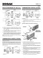
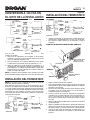
FIELD CONVERSION TO 120 V.A.C.
THERMOSTAT INSTALLATION
OPTIONAL LINE VOLTAGE WALL-MOUNT THERMOSTAT
1. Locate thermostat on an inside wall away from all drafts and
approximately 4-5 feet above the floor.
2. Route all wiring through the thermostat first and then to the
heater.
OPTIONAL (MODEL 90) UNIT-MOUNT THERMOSTAT
If a 120 V.A.C. circuit is to be used, make wiring changes as follows:
1. Disconnect white wire from heater element terminal “2” and
connect it to terminal “4.” The heater will now operate at 120
V.A.C., 750W, 6.3A.
2. For 120 V.A.C, 1500W, 12.5A operation, add the short red jumper
wire (provided) between terminals “1” and “2”.
3. Remove alarm light wire leads from terminals “1” and “3” of
the high temperature limit. Remove white wire lead from limit
terminal “1” and reconnect at limit terminal “3”. Secure wire leads
with wire tie so there is no interference with unit operation.
NOTE: Terminal numbers are marked on the side of the blower
housing, above the heater elements.
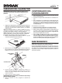
THERMOSTAT INSTALLATION
NOTE: The thermostat control circuit must be wired prior to the
wiring of the heater unit.
This heater may be thermostatically controlled by either a line volt‑
age wall-mounted thermostat (Model 86W), or an optional built-in
thermostat accessory kit (Model 90). Model 90 thermostat kits are
designed for easy installation with this heater. Instructions for in‑
stalling thermostats are provided below and are also supplied with
each thermostat kit.
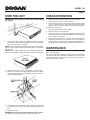
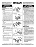
1. Remove the top cover from the heater.
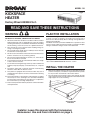
2. Remove the 5/8” knockout located on the left side of the front
panel (use a screwdriver to remove the knockout). Also remove
the two plastic hole plugs (see illustration).
3. Install thermostat from back side of front panel and fasten in
place, from front, with two screws and washers provided (see
illustrations).
4. Attach temperature control knob by gently pushing it on to the
thermostat shaft. Flats on shaft and knob must line up for proper
installation (do not force control knob onto shaft).
5. Remove black wire from thermal fuse and attach it to thermostat
terminal marked “4”.
6. Remove white wire from temperature limit terminal marked “1”
(Note: the other end of this wire is attached to incoming field
wiring) and attach it to the thermostat terminal marked “1”.
7. Attach black thermostat wire to thermal fuse and white ther‑
mostat wire to the temperature limited marked “3”.