Transcript
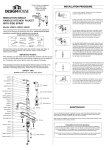
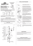
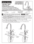
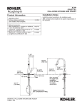
Design
MIDDLETON SINGLE
HANDLE SHOWER
FAUCET
Shut off main water supply. Preparation/Assembly of
recommended component locations: Valve depth should be front of
valve to front of the finished wall of approx. 2-3/16" (1=7/8" - 2-1/2"
max); Shower and/or spout outlet hole should be 1-1/4" diameter,
and Valve access hole should be 6" diameter. Caution: Allow at least
2" between the tub outlet and tub rim.
Models 545806, 545780, 545798
House
m)
00m mm)
0
(12
48” ”(150
- 60
m)
.2m
203
8”(
Pipe should stick outside
finished wall by 4”
3. Plaster guard is preinstalled. The front surface
of the plaster guard should sit flush with the finished
surface of the wall.
Wrap threaded connections (except where o-ring or rubber sealant are present)
with Teflon tape available from your local hardware or plumbing supply store.
Always wrap in a clockwise direction.
4.
INSTALLATION PROCEDURE, CONTD.
5
6
4
4
5.
5a. Place handle on valve stem and turn handle
to full on mixed position. Turn on hot and cold
water lines to full open for one minute each.
Check for leakage. Shut off water at faucet.
Remove the Handle. REMARK: Adjust the water
temperature by adjusting the rotational limit.
Remove the red rotational limit stop from the
valve by sliding it off the stem. Rotate counter
clockwise to increase temperature or clockwise
to reduce temperature. Re-install in correct
position.
6. With gasket in place, slide escutcheon over
trim sleeve. Fasten escutcheon to faucet body
and tighten to finished wall surface using two
mounting screws.
Handle
01
Screw
02
Color button
03
Cover
04
Escutcheon
05
24
08
7. Slide handle onto
shaft.
8. Insert screw through
handle and thread to
faucet body. Insert
button over set screw.
Screw
23
Plaster
Screw
25
Washer
26
Plug
22
Gasket 06
Shower
Trim sleeve 07
Nut 13
O-ring 14
Valve stem 15
O-ring 16
8
4
Thread shower head onto shower
arm.
Spring 17
7
Pipe should stick outside
finished wall by 4”
09
Cartridge
10
O-ring
11
Body
12
Diversion valve
21
Shower arm
20
Flange
Spool 18
Washer 19