1
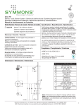
Duro™ Tub-Shower Systems S-3600, S-3601, S-3602 Series Installation and Service Instructions Need Help? Model Number Series S-3602........... Tub-Shower System S-3602-X....... Valve includes stops S-3602-TRM.. Trim only S-3600........... Shower Valve System S-3600-X....... Valve includes stops S-3600-TRM.. Trim only S-3601........... Shower System S-3601-X....... Valve includes stops S-3601-TRM.. Trim only S-3600TS...... Tub-Shower Valve Sys. S-3600TS-X... Valve includes stops Symmons customer service: (800) 796-6667, (781) 848-2250 [email protected] Mon - Fri 7:30 am - 7:00 pm EST www.symmons.com/service • Technical help • Product information • Warranty policy Visual Guide Duro Tub-Shower Systems S-3600, S-3601, S-3602 Series Tools & Materials Model Series S-3601 S-3601-X S-3601-TRM S-3602 S-3602-X S-3602-TRM Arm and flange 300S 1/8" 1 Model Series S-3600 S-3600-X S-3600-TRM S-3601 S-3601-X S-3601-TRM 2 3 Showerhead 362SH 4 S-3602 S-3602-X S-3602-TRM S-3600TS S-3600TS-X Screwless escutcheon kit RTS-003 Temptrol® Control Valve Temp Limit stop screw S-4001-BODY S-4001-X-BODY S-4002-BODY S-4002-X-BODY HOT supply inlet Handle kit RTS-002 1/8" Mounting plate, T-177 Dome cover Escutcheon Escutcheon mounting plate Volume control handle or diverter handle RTS-004 Note: Piping, fittings and tools are not included. Actual plumbing should be determined and installed by a licensed plumber. Protective valve shield (not shown) T-176 Tub spout 067 COLD supply inlet Model Series S-3600 S-3600-X S-3600TS S-3600TS-X S-3601 S-3601-X S-3602 S-3602-X Model Series S-3602 S-3602-X S-3602-TRM Installation Instructions Rough-in Installation Control valve assembly, piping and fittings (Note: Illustrations below show valve model without stops) Reference as required: Page Visual guide.....................................1 Dimensions illustration.................4 1) Determine wall thickness ■■ D etermine type of wall and wall thickness where valve will be mounted. ■■ Consider whether to use mounting plate by reviewing figure 2 below. ■■ Skip ahead to Step 3 if mounting plate is not used. 2) Attach valve mounting plate ■■ Reference figure 2 to determine whether shield is required. ■■ Attach protective shield by snap fitting over end of valve spindle. 4) Install piping, fittings and ■■ ■■ ■■ Seat mounting plate against valve assembly as illustrated in figure 1. ■■ control valve Piping and fittings not supplied Control Valve Install through cutout hole in wall as specified in figure 2 below and dimension illustration on page 4. Showerhead (S on valve) Pipe from outlet port on valve marked S to showerhead mounting arm location. Hot & Cold Supply (H & C) Pipe hot water supply to valve inlet marked H and cold water supply to valve inlet marked C. Tub Spout (T on valve) Pipe from outlet port on valve marked T to tub spout. Important! Do not substitute Tub Spout with restrictive fittings such as PEX, CPVC or outlet accessories such as a ledge spout, hose and spray that would subject the valve to excessive internal back pressure, otherwise operation will be compromised. Figure 1 Mounting plate Walls for using T-177 mounting plate 6) Adjust valve packing nut Reference figure 3 below ■■ Turn hot & cold supplies on. Valve will not operate unless both hot and cold water supply pressures are turned on. ■■ Place handle over end of control spindle stem. ■■ Adjust packing nut for positive frictional resistance as handle is rotated from shutoff position across adjustment range. Temp Limit stop screw packing nut control spindle stem finished wall finished wall Ensure valve’s mounting plate is flush against inner wall 2-3/8" ± 1/2" (60 mm ±13 mm) pipe centerline to finished wall Finished wall must be flush with back side of protective shield surface Protective shield "snap on-off" (required when mounting plate is not used) p/n T-177 wall cutout hole size 3-1/2" (89 mm) min 4" (101 mm) max wall cutout hole size 3-1/2" (95 mm) min 4" (101 mm) max Figure 2 Mounting valve Page 2 wall Figure 3 Valve adjustments 1/2" (13 mm) or greater "snap on-off" p/n T-176 If protective shield was attached in Step 3 then remove shield snap fitted over the end of valve spindle once valve is securely installed and wall finish work has been completed. Dry wall, plaster or other type wall Fiberglass or acrylic walls (required) Plaster or other type walls (optional) 1/16" (2 mm) min 1/2" (13 mm) max Protective shield When mounting plate is used, then shield is optional for protecting end of valve during installation. 5) Remove protective shield 3) Attach protective shield 7) Flush system, check for leaks 2) Attach escutcheon 5) Attach showerhead ■■ Turn valve to the warm position and run for a few minutes. ■■ If system is dirty, remove valve spindle in center of valve to ensure proper flushing. (See service instructions.) ■■ Check for leaks around valve assembly and all pipe fittings. 6) Attach tub spout 8) Set Temp Limit stop screw Reference page 2, figure 3 The temperature limit stop screw limits valve handle from being turned to maximum position resulting in excessive hot water discharge temperatures. Warning: Failure to adjust Temp Limit stop screw properly may result in serious scalding. Diverter & Volume Control Handle Operation ■■ Place handle on control spindle stem and open valve to maximum desired temperature. ■■ Turn Temp Limit stop screw clockwise until it seats. Note: Do not install positive shutoff devices on control valve outlet or devices that do not allow the valve to flow at least 1.5 gpm. Diverter handle Tub-Shower models 3) Attach dome cover Tub Shower Volume control handle Shower only models Trim Installation 1) Attach escutcheon mounting plate 4) Attach handle High Low Care and Cleaning Clean finished area using mild soap and water or a non-abrasive cleaner and then quickly rinse. A non-abrasive wax may be used to preserve finish area. 1/8" factory installed gasket Page 3 Dimensions Duro Tub-Shower Systems, S-3600, S-3601, S-3602 Series Model Series S-3601 S-3601-X S-3602 S-3602-X finished wall 2-1/2" dia (64 mm) 6" (151 mm) 1/2"-14 NPT 4-5/8" (118 mm) Model Series S-3600 S-3600-X S-3600TS S-3600TS-X S-3601 S-3601-X S-3602 S-3602-X approx 77" (1956 mm) showerhead supply outlet Finished wall to pipe centerline 2-3/8" ± 1/2" (60 mm ±13 mm) *see note (2) 5/8" (16 mm) Finished wall to rear of valve 3-1/2" ± 1/2" (89 mm ±13 mm) Wall cutout hole size 3-1/2" (89 mm) min 4" (101 mm) max mounting plate p/n T-177 *Note (1) 7-1/2" sq (191 mm) Temptrol control valve 3-1/8" (80 mm) HOT supply inlet COLD supply inlet 12" (305 mm) Model Series S-3602 S-3602-X tub spout supply or supply plug 3-3/8 ±½" (85 mm) (±13 mm) HOT / COLD supply inlets 1/2"-14 NPT 2-1/2" dia (64 mm) 5-1/4" (133 mm) 7" (178 mm) (also reference page 2, figure 2 for details) * Notes: (1) Walls for using T-177 mounting plate (MP) ■ Wall is 1/16" (2 mm) min • 1/2" (13 mm) max ■ Fiber or acrylic walls (MP is required) ■ Plaster or other type walls 1/2" or less (MP optional) ■ Protective shield usage (optional for protection only) (2) Dry wall, plaster or other type walls 1/2" or greater ■ Protective shield attached to valve spindle to locate position (3) Dimensions subject to change without notice Page 4 approximately Shower only = 42" (1067 mm) Tub-Shower = 32" (813 mm) Protective shield p/n T-176 Floor Parts Assembly Temptrol Shower & Tub-Shower Control Valves ■ S-4002-BODY......Tub-Shower valve ■ S-4001-BODY......Shower valve ■ S-4001-X-BODY..Shower valve w/stops ■ S-4002-X-BODY..Tub-Shower valve w/stops Service stop kit (T-52) Removal tool Temptrol valves S-4001-BODY S-4002-BODY HOT & COLD seat COLD seat removal repair kit (TA-4) Service stop kit & removal tool (T-55C) COLD supply inlet Shower supply outlet HOT seat removal tool (T-35A) Service stop Retainer Temptrol valves S-4001-X-BODY S-4002-X-BODY tool (T-35B) HOT seat HOT supply COLD seat Control spindle & cap assembly (TA-10 & T-12A) inlet Shower only, Tub supply plug Tub-Shower, Tub supply outlet Service stop 5/16" Allen wrench Pull out to remove Shower only volume spindle (black or gray) TA-25B Tub-shower diverter spindle (white) TA-25A Control spindle assy. (TA-10) Temp Limit stop adjust 5/16" wood screw Control spindle washer repair kit (TA-9) hot washer screw hot washer cold washer retainer cold washer cap gasket Cap assembly (T-12A) cap gasket cap limit stop screw o-ring washer Cap washer repair kit packing (T-16) packing nut Temptrol Valve Replacement Parts and Optional Tools Symmons Part Number Valve Body Type S-4001-BODY S-4002-BODY Description S-4001-X-BODY S-4002-X-BODY TA-4 √ √ HOT & COLD seat repair kit...........(optional tool p/n T-35A/B) TA-9 √ √ Control spindle washer repair kit TA-10 √ √ Control spindle........... (includes p/n TA-9 & T-16 components) T-12A √ √ Cap assembly T-16 √ √ Cap washer repair kit TA-25A S-4002-BODY S-4002-X-BODY Diverter spindle kit .......................(white appearance) TA-25B S-4001-BODY S-4001-X-BODY Volume control spindle kit.......(black or gray appearance) T-35A/B √ √ HOT seat removal tool, T-35A & COLD seat removal tool, T-35B T-52 √ Service stop spindle & retainer T-55C √ Service stop spindle, retainer & removal tool √ Reverse seat & tool kit (valve HOT & COLD supply inputs are reversed) T-108 √ Page 5 Trouble Shooting Chart Problem Cause Solution Valve will not pass water. Both hot and cold water supplies are not turned on. Turn on both supplies. Valve will not operate unless both hot and cold water pressure is on. Valve leaks when shut off. Hot and cold washers are worn or foreign matter (dirt, chips) is lodged between washers and seat surfaces. 1) Replace washers using control spindle washer repair kit, p/n TA-9. 2) Replace hot & cold seats using hot/cold seat repair kit, p/n TA-4. Temperature control handle is turned from cold to hot (or hot back to cold) and volume from spout or head is not constant. Pressure-balancing piston housed in spindle assembly is restricted from free movement by foreign matter. 1) Open valve halfway, remove handle and tap spindle with plastic hammer. 2)Check water pressure balancing piston in control spindle. See service instructions. 3)Replace control spindle, p/n TA-10. Valve delivers sufficient quantity of cold, but little hot, or the reverse. Temperature varies without moving handle. Same as above Same as above Same as above Same as above Valve delivery temperature reduces gradually during use; handle must be turned to hotter positions to maintain constant temperature. Overdraw on hot water supply (i.e. running out of hot water). Reduce maximum flow by using volume control adjustment on valve or showerhead. This will allow longer period of use before overdrawing hot water supply. Valve delivers hot water when initially opened. Water turns colder as handle is rotated in a counter-clockwise direction toward the hot position. Valve is piped incorrectly (i.e. the hot supply is piped to the valve’s cold inlet and the cold supply is piped to the hot inlet.) If piping is accessible, correct connections to the valve. If piping is not accessible, order a reverse seat and tool kit, p/n T-108. Older installations may also require replacing the hot seat, hot/cold seat repair kit, p/n TA-4. When tub-shower valve’s diverter handle is set in shower position a pencil width stream of water runs from the tub spout. Up to a pencil width stream of water may flow from the tub spout to ensure the water has been shut off at the main valve only. Service Instructions Removing control spindle assembly (Ref. parts assembly figure) ■■ Shut off water supply to valve and remove control valve handle and dome cover. ■■ Remove escutcheon plate by first removing escutcheon screws. ■■ Turn valve’s control spindle to half way position between minimum and maximum rotation. Important: Failure to do this can damage control spindle assembly. ■■ Unscrew both spindle cap and control spindle assembly. Hot/Cold seat repair kit Order p/n TA-4, T-35A and T-35B. Installation requires both hot & cold removal tools, p/n T-35A & T-35B. ■■ Remove control spindle assembly. ■■ Remove both seats with removal tools. ■■ Replace both seats even if only one appears worn. ■■ Install and tighten both seats to 15 foot pounds of torque. Control spindle washer repair kit Order p/n TA-9. ■■ Remove control spindle assembly. ■■ Remove cold washer by holding spindle using valve handle and unscrew cold washer retainer using channel lock pliers. ■■ Remove hot washer by removing hot washer screw. Checking water pressure balancing piston The perforated end of the control spindle assembly houses the water pressure-balancing piston which is the heart of the valve. ■■ Remove control spindle assembly. ■■ Shake spindle assembly and listen for clicking noise. Piston should be free to slide back and forth the full length of its travel. ■■ If piston appears restricted then do the following: (1) Tap the handle or stem end of the spindle against a solid object to free the piston. (2) Try soaking in household vinegar and repeat step (1). ■■ If unable to free piston, replace control spindle, p/n TA-10. Important: Do not attempt removal of the piston. Valve re-assembly Reassemble by reversing above procedures. After the control spindle assembly (TA-10) is threaded back into the spindle cap assembly (T-12A) ensure control spindle is rotated 1/2 turn clockwise from its maximum counter clockwise rotational position. Failure to do this will damage assembly. Symmons Industries, Inc. 31 Brooks Drive ■ Braintree, MA 02184 ■ (800)796-6667, (781)848-2250 ■ Fax (800)961-9621, (781)664-1300 ©2012 Symmons Industries, Inc. ■ www.symmons.com ■ [email protected] ■ ZV-1062 ■ 050912