1
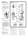
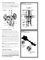
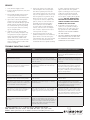
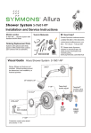
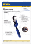
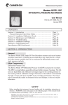
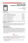
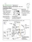
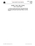
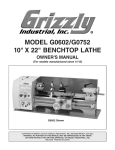
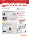
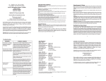
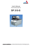
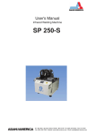
Temptrol®
Single Handle Pressure-Balancing Mixing Valve for Shower or Tub/Shower Application
INSTALLATION, OPERATION & SERVICE INSTRUCTIONS
Symmons valves and shower heads comply to all known standards, codes and
specifications: CSA B-125, ANSI A112.18.1M, ASSE 1016, EPA ‘92 etc.
Symmons shower heads are equipped with a 2.5 GPM (9.5 L/min) water and energy
saving flow restrictor..
LIFETIME LIMITEd WARRANTy
Symmons warrants to the original consumer purchaser that any TEMPTROL® series* or SYMMETRIX®
product will be free of defects in material and workmanship during normal domestic use for the life of
your home. All other products and purchasers including industrial, commercial or business use are
warranted for a period of 5 years from the date of purchase. At our option, we will either have you send
the defective part or product prepaid to us for inspection, or we may elect to send you the replacement
part or product without investigation. A replacement for any defective part will be supplied FREE OF
CHARGE for installation by the purchaser. Defect or damage caused by the use of replacement parts
other than Symmons Genuine Replacement Parts will void this warranty. This warranty excludes product
damage due to installation error, product abuse, or product misuse whether performed by a contractor,
service company or yourself.Symmons further warrants that any TEMPTROL or SYMMETRIX product will
be leak free and drip free during normal domestic use for the life of your home. If the product should
develop a leak or drip, Symmons will provide FREE OF CHARGE the parts necessary to return it to good
working condition.Proof of purchase (original sales receipt) and a copy of the warranty registration card
from the original consumer purchaser must accompany all warranty claims. This warranty is applicable
only to Symmons TEMPTROL or SYMMETRIX products purchased after July 1, 1998 and shall be effective
from the date of purchase as shown on the purchaser’s receipt.Damage to the chrome and/or other
decorative finishes on Symmons products may be a result of improper handling or abusive treatment.
Finishes should only be cleaned with a soft, damp cloth or sponge. Use of polish, abrasive cleaners,
solvents, or acid cleaners will damage the finish and void this warranty.There are no other express
warranties on this product and ALL WARRANTIES OF MERCHANTABILITY AND OTHER IMPLIED
WARRANTIES ARE LIMITED IN ACCORDANCE WITH APPLICABLE LAW. SYMMONS INDUSTRIES, INC.,
EXPRESSLY DISCLAIMS CONTINGENT LIABILITY AND CONSEQUENTIAL DAMAGE OF EVERY KIND. Since
some states do not allow limitations on how long an implied warranty lasts or an exclusion or limitation
of incidental or consequential damages the above limitation or exclusion may not be applicable. This
warranty gives specific legal rights. Other rights may vary from state to state.To obtain warranty service,
write to Symmons Industries, Inc., 31 Brooks Drive, Braintree, MA 02184-3804 or call our Customer
Service Department at 1-800-SYMMONS. If writing to us, please include proof of purchase, the model
number of the product with a brief description of the problem, your name, address and phone number.
*Temptrol series includes Allura®, Olde Braintree Brass®, Temptrol, Temptrol Deluxe and Temptrol II
shower and tub/shower systems.
IMPORTANT: After completion of installation step 4, follow these instructions to set the
Temptrol Limit Stop Screw. This valve is equipped with a limit stop screw to be used to
limit valve handle from being turned to excessively hot water discharge temperatures.
To adjust, remove dome cover, open valve to maximum desired temperature and turn
in limit stop screw until it seats.
WARNING: Failure to adjust the limit stop screw properly may result
in serious scalding.
WARNING: This shower system may not protect the user from scalding
when there is a failure of other temperature controlling devices
elsewhere in the plumbing system.
For ADA compliance (Americans with Disabilities Act) consult ADAAG or your state
regulations for proper product choice and mounting locations.
Please read all instructions carefully before starting
installation. Save this manual for future reference.
Installation of:
Shower systems and
Tub/Shower systems
Figure 2
Model A: Tub/Shower System
Tools required for installation of this product
are: Phillips screw driver, tubing cutter,
teflon tape, soldering equipment, adjustable
wrench and channel-lock pliers.
4 7/8"
124mm
1. Install piping and fittings with valve body
as shown in Figure 2 or 3. IMPORTANT:
Valve rough-in is 2-3/8” +/- 1/2”
from CENTERLINE OF SUPPLIES TO
FACE OF FINISH WALL. Install so that
line indicated on rough-in plaster shield
(T-176) on valve is flush with finish wall
as shown in Figure 1 (See Figure 5 for
fiberglass wall installation).
6 3/8"
162mm
approx.
44 7/8"
1140mm
Figure 1
plaster shield
(T-176)
3" (75mm) Min
4" (101mm) Max
finish wall face
2 38 '' +
60mm
1
''
2
CL supplies
Tub/Shower System (Figure 2)
Model A
Pipe shower head from outlet marked
“S” and to tub spout from outlet marked
“T”. The diverter mechanism in this
valve is designed so that it cannot be
subject to any back pressure, other than
is imposed by the spout supplied with
this package. DO NOT SUBSTITUTE
OTHER OUTLET ACCESSORIES FOR
THE TUB SPOUT (SUCH AS HOSE
AND SPRAY, SHOWER HEAD, BODY
SPRAY, LEDGE SPOUTS, ETC.) OR
ANY PIPE ADAPTER OR ADDITIONAL
FITTINGS (SUCH AS PEX, ETC.)
THAT CAN CAUSE BACK PRESSURE
THROUGH THE VALVE. Install HOT on
left and COLD on right according to valve
markings.
Shower System (Figure 3)
Model B
Pipe to shower head from outlet marked
“S”. DO NOT REMOVE PLUG FROM
OUTLET MARKED “T”. Install HOT on left
and COLD on right according to valve
markings.
Tub/Shower, Shower or Tub
System (Figure 2A) Model C
Tub/Shower System: The valve in this
system has a built-in choke for use with a
diverter spout. Follow piping instructions
for Model A valve.
fIGure 2A
model C: diverter spout installation
Shower System: Pipe shower head
from outlet marked “S”. Install either the
included copper sweat or 1/2”-14 NPT
plug (pipe sealer required) into the outlet
marked “T” (see figure 3A).
Tub only System: Pipe tub spout from
outlet marked “T”. Install either the
included copper sweat or 1/2”-14 NPT
plug (pipe sealer required) into the outlet
marked “S” (figure 3A).
2. When finishing tile wall PULL OFF
ENTIRE PROTECTIVE PLASTER SHIELD
(T-176). If finish wall obstructs removal
of plaster shield, break off outer edge
along perforations (if necessary, carefully
use sharp blade to facilitate removal).
Page 2
After plaster shield is removed FILL AREA
AROUND VALVE BODY WITH GROUT OR
PLASTER.
3. TURN ON HOT AND COLD SUPPLIES,
valve will not operate unless both hot
and cold water are turned on.
4. Unscrew dome cover (T-19/20) and
tighten packing nut (T-17) for positive
frictional resistance to handle turn
throughout adjustment cycle and at shutoff position. Check valve cap, packing
nut, diverter spindle o-ring and all valve,
pipe and fitting connections for leaks.
5. SET LIMIT STOP SCREW AS DIRECTED
AFTER “IMPORTANT” IN BOLD TYPE ON
PAGE ONE. Reattach dome cover back
onto packing nut.
6. Mount gasket (T-27B) onto back of
escutcheon with opening at bottom as
shown in Figure 4. The use of this gasket
should not preclude sealing valve body in
wall as directed in installation instruction
step #2.
Figure 3
Model B: Shower System
4 7/8"
124mm
Figure 4
6 3/8"
162mm
T-27B
approx.
28 7/8"
733mm
7. Assemble dial plate and escutcheon by
sliding volume control handle with clip
(T-27CL) into slot in escutcheon as shown
in Figure 9. Remove protective coating
from dial plate.
8. ALLOW VALVE TO RUN IN WARM
POSITION FOR A FEW MINUTES TO
TOTALLY FLUSH SYSTEM. IF SYSTEM IS
QUITE DIRTY, REMOVE VALVE SPINDLE
OR STOP SPINDLES (IF SO EQUIPPED) TO
INSURE PROPER FLUSHING. See service
instructions.
8. Install escutcheon on valve making sure
diverter/volume shaft (A) aligns with
mating key slot in top of diverter/volume
spindle (B) (Models A and B only).
A.
B.
Push assembled escutcheon against wall
and secure to valve with two escutcheon
screws (T-28). Mount temperature control
handle on valve spindle spline as shown
in figure 9. Install shower arm, flange and
shower head. See Figures 2 and 3.
9. Do not install positive shut-off devices
on the outlet of this valve or devices that
do not allow the valve to flow at least 1
GPM at 50 psi inlet pressure. EXCEPTION:
If a self-closing or slow-closing valve is
installed on the outlet, the supplies of the
valve must be equipped with checks to
eliminate hot to cold by-pass in the event
the valve’s handle is not turned to off after
use. Contact your factory representative
or Symmons directly for information on
available checks.
FIBERGLASS WALL INSTALLATION
Figure 3A
Install plug here for
tub only installation
Copper sweat plug
or
1/2"-14 NPT plug
(pipe sealer required)
Install plug here for
shower only installation
Figure 5
T-177 Wall Mounting Flange
1
''2mm
16
3
to 4 ''19mm
THICK WALL
13
For 16 '' 21mm to 1" 25mm
thick wall order part no. T-193
When installing Temptrol® in fiberglass or
panel walls and it is desired to sandwich
wall between valve body and escutcheon,
cut hole in wall as shown in Figure 5 and
mount valve with T-177 wall mounting
flange from rear. Note: It is always
recommended to secure valve piping
to rough construction and not
depend on fiberglass wall for valve
mounting security. On panel walls over
1” thick, install in conventional manner.
HOLE SIZE
3" (75mm) Min
4" (101mm) Max
Page 3
BACK TO BACK INSTALLATION
To simplify piping on back to back installations use one standard valve (hot on left, cold on right) and one with reverse
coring (hot on right, cold on left) as shown in Figure 6 and
7. Order reverse core valve by adding the suffix REV-X
after the plate number. (e.g. S-96-2-REV-X Temptrol® tub and
shower unit with reverse coring.)
Figure 7
Back to Back Installation
6 14 ''
159mm
MINIMUM WALL
THICKNESS
3 18 '' +
Figure 6
1
''
2
1
'' 13mm
2
79mm
shower
discharge
STANDARD
VALVE
REVERSE
CORE
VALVE
hot and cold
inlets
HOT
HOT
2 38 '' +
1
''
2
60mm
COLD
5
2 8 '' +
COLD
1
''
2
COLD
67mm
tub discharge
OPERATION OF VALVE
The main handle of the Temptrol valve is for control of
temperature only. From the OFF position, the handle is
turned counter-clockwise through a minimum cold position,
through a warm and hot position for a maximum turn of
approximately one revolution. This allows for wide range of
temperature adjustments to suit the requirements of the user.
Figure 8
Seat Removal Tools
Model A (tub and shower) is equipped with a combination
diverter and volume control. The small lever handle below
the temperature control handle can be moved to the left for
tub flow and to the right for shower flow. For volume reduction in either tub or shower position, move the small lever
handle below the temperature control handle slowly toward
the center or vertical position to obtain the desired reduction
in water volume.
Model B (shower only) is equipped with a built-in volume
control. The small lever handle below the temperature
control handle can be moved from left to right to obtain a
reduction in water volume.
Model C (tub or shower) does not have the added feature
of volume control built into the valve.
NOTCH
T-35A
T-35B
FOUR BROACHED
NOTCHES TO
ENGAGE FOUR
CORNERS
OF HOT SEAT
TOOL.
CARE AND CLEANING
The lustrous finish on your Temptrol valve should be treated
with care. It can be readily damaged by improper handling or
abusive treatment. To clean the finish wipe gently with a soft
damp cloth and blot dry with a soft towel. Use only a mild
soap solution if required. DO NOT USE ABRASIVE CLEANERS. Use of polish, abrasive cleaners, solvents
or acid cleaners will damage the finish and
VOID the Symmons warranty.
Page 4
EIGHT BROACHED NOTCHES
TO ENGAGE FOUR CORNERS
OF COLD SEAT TOOL IN TWO
POSITIONS.
IndIVIduAL PArTS
SC-15A
T-1
T-2
T-3
T-5
T-6
T-7
T-8
TA-10
T-11
T-12A
T-16
T-17
T-19/20
T-21C
T-23A
IndIVIduAL PArTS
TA-4
Handle set screw
Hot renewable seat
Cold seat O-ring
Cold renewable seat
Hot washer screw
Hot washer
Cold washer retainer
Cold washer
Flow control spindle
Cap gasket
Cap assembly
Packing, O-ring and washer
Packing nut
Dome cover and lock nut
Diverter retainer
Diverter spindle (Model A)
(beige or gray)
Diverter spindle (Model B)
(black)
Spindle O-ring
Escutcheon
Diverter handle clip
Gasket
Escutcheon screws
Dial (Model A)
Dial (Model B)
Dial (Model C)
T-23B
T-24
T-27
T-27CL
T-27B
T-28
T-29A
T-29B
T-29C
ComPoSITe PArTS
TA-9
TA-10
TA-25A
(T-23A)
TA-25B
ComPoSITe PArTS
RC-14X
T-52
T-101
T-31
Single blade lever handle:
Set screw (SC-15A)
Stop spindle assembly/
escutcheon screw retainer
(T-52A)
Stop plaster shield (T-55B)
Acrylic handle:
Handle screw (T-32)
Plug button (T-33)
T3-31L
T3-31S
Hot seat (T-1)
Cold seat (T-3)
Cold seat O-ring (T-2)
Hot washer screw (T-5)
Hot washer (T-6)
Cold washer retainer (T-7)
Cold washer (T-8)
Cap gasket (T-11)
Spindle assembly
Diverter/volume spindle
O-ring (T-24) for Model A
tub/shower valve (beige
or gray)
Volume spindle (T-23B)
O-ring (T-24) for Model B
shower valve (black)
Temperature control handle:
Handle screw (T-32)
Plug button (T3-33R)
Loop style lever handle:
Insert (T3-31 INS)
Handle screw (T-32)
Plug button (T-33)
Solid style lever handle:
Insert (T3-31 INS)
Handle screw (T-32)
Plug button (T-33)SC-15A
Figure 9
Parts Breakdown
T-35A
T-34
T-35B
T-1 T-2 T-3
T-5 T-6 T-7 T-8
TA-4
TA-9
INCLUDES T-11
TA-10
T-11
T-16
T-17
T-19/20
T-12A
T-177
T-52A
T-55B
T-21C
MAIN
SECTION
OF VALVE
T-23A
T-23B T-24
TA-25A, TA-25B
T-176
TO BE DISCARDED
BEFORE INSTALLING
TRIM
FRON T VIE W OF
DIVERTER-VOLUM E
SPINDL E
T-52
T-55C
T-27CL
T3-31 INS
T-27B
T-27
T-28
(2)
T-29A T-29A-SS
T-29B T-29B-SS
T-29C T-29C-SS
SC-15A
(for T3-31L
and T3-31S
only)
T-30
T-31
T3-31L
Page 5
T3-31S
T-101
T-32
T-33
RC-14X
4%-042/,¤¤3%2)%33%26)#%).3425#4)/.3
4%-042/, 3%2)%33%26)#%).3425#4)/.3
SERVICE
3HUTOFFWATERSUPPLYTOVALVE
)NSPECTTOPSURFACESOFHOTANDCOLD
SEATSANDREPLACEIFNECESSARY)MPOR
3HUTOFFWATERSUPPLYTOVALVE
2EMOVEHANDLEPLUGBUTTON4AND )NSPECTTOPSURFACESOFHOTANDCOLD
TANT7HENREPLACINGHOTANDCOLD
SEATSANDREPLACEIFNECESSARY)MPOR
HANDLE4
2EMOVEHANDLEPLUGBUTTON4AND
SEATSALWAYSREPLACEBOTHSEATS%VENIF
TANT7HENREPLACINGHOTANDCOLD
HANDLE4
2EMOVEDIAL;4!"#=ANDESCUTCH
ONLYONESEATAPPEARSWORNBOTHSEATS
SEATSALWAYSREPLACEBOTHSEATS%VENIF
EON4BYREMOVINGESCUTCHEON
2EMOVEDIAL;4!"#=ANDESCUTCH
MUSTBEREPLACED5SEPART.O4!
ONLYONESEATAPPEARSWORNBOTHSEATS
SCREWS42EMOVEALLREMAININGTRIM
EON4BYREMOVINGESCUTCHEON
!FTERLONGYEARSOFSERVICEIFSPINDLE
MUSTBEREPLACED5SEPART.O4!
SCREWS42EMOVEALLREMAININGTRIM
/PENVALVETOABOUTWARMPOSITION
!FTERLONGYEARSOFSERVICEIFSPINDLE
ISVERYLOOSEINCOLDSEATREPLACEWITH
/PENVALVETOABOUTWARMPOSITION
ANDUNSCREWCAP4!7ARNING
ISVERYLOOSEINCOLDSEATREPLACEWITH
PARTNO4!5SESEATREMOVALTOOL
ANDUNSCREWCAP4!7ARNING
&AILURETODOTHISWILLDAMAGECAPAND
PARTNO4!5SESEATREMOVALTOOL
;4!"=FORREMOVALANDREPLACE
&AILURETODOTHISWILLDAMAGECAPAND
SPINDLE3PINDLEASSEMBLY4!WILL
;4!"=FORREMOVALANDREPLACE
MENTOF4!)FSEATSAREDIFlCULT
SPINDLE3PINDLEASSEMBLY4!WILL
BEREMOVEDWITHCAP,EAVEPACKING
MENTOF4!)FSEATSAREDIFlCULT
TOREMOVEANDTOOLSHIFTSDAMAGING BEREMOVEDWITHCAP,EAVEPACKING
NUT4INPLACEWHILEUNSCREWING
TOREMOVEANDTOOLSHIFTSDAMAGING
NOTCHESRELOCATETOOLINSECONDPOSI
NUT4INPLACEWHILEUNSCREWING
CAPTOAVOIDDISTORTION
NOTCHESRELOCATETOOLINSECONDPOSI
TIONOFNOTCHES4IGHTENBOTHSEATSTO
CAPTOAVOIDDISTORTION
TIONOFNOTCHES4IGHTENBOTHSEATSTO
FOOTPOUNDSOFTORQUE
/RDINARYSERVICETOELIMINATEDRIP
FOOTPOUNDSOFTORQUE
/RDINARYSERVICETOELIMINATEDRIP
PINGORNOTSHUTTINGOFFREQUIRESONLY
4HEPERFORATEDENDOFTHE4!
PINGORNOTSHUTTINGOFFREQUIRESONLY
THEREPLACEMENTOFPARTSSUPPLIEDIN 4HEPERFORATEDENDOFTHE4!
SPINDLEASSEMBLYHOUSESTHEBALANCING
THEREPLACEMENTOFPARTSSUPPLIEDIN
SPINDLEASSEMBLYHOUSESTHEBALANCING
WASHERANDGASKETKIT4!(OLD
PISTONWHICHISTHEHEARTOFTHISPRES WASHERANDGASKETKIT4!(OLD
PISTONWHICHISTHEHEARTOFTHISPRES
SPINDLEWITH4HANDLEWHILE
SUREBALANCINGVALVE4HEPISTONSHOULD
SPINDLEWITH4HANDLEWHILE
SUREBALANCINGVALVE4HEPISTONSHOULD
REMOVINGHOTWASHERSCREWANDCOLD
BEFREETOMOVEBACKANDFORTHAND
REMOVINGHOTWASHERSCREWANDCOLD
BEFREETOMOVEBACKANDFORTHAND
WASHERRETAINERREMOVERETAINERWITH
SHOULDCLICKWHENTHESPINDLEASSEMBLY
WASHERRETAINERREMOVERETAINERWITH
SHOULDCLICKWHENTHESPINDLEASSEMBLY
CHANNELLOCKPLIERS
CHANNELLOCKPLIERS
ISSHAKEN)FDEPOSITSBLOCKTHISACTION
TAPTHEHANDLEENDOFTHESPINDLE
ISSHAKEN)FDEPOSITSBLOCKTHISACTION
AGAINSTASOLIDOBJECTTOFREETHEPISTON
TAPTHEHANDLEENDOFTHESPINDLE
3OAKINGINHOUSEHOLDVINEGARWILL
AGAINSTASOLIDOBJECTTOFREETHEPISTON
HELPFREEFOREIGNMATTER)FTHISDOES
3OAKINGINHOUSEHOLDVINEGARWILL
NOTFREEPISTONREPLACE4!SPINDLE
HELPFREEFOREIGNMATTER)FTHISDOES
ASSEMBLY$/./44!-0%27)4(
NOTFREEPISTONREPLACE4!SPINDLE
ASSEMBLY$/./44!-0%27)4(
0%2&/2!4%$#9,).$%2/.4(%
0%2&/2!4%$#9,).$%2/.4(%
30).$,%!33%-",9/2!44%-04
30).$,%!33%-",9/2!44%-04
2%-/6!,/&4(%0)34/.
2%-/6!,/&4(%0)34/.
2EASSEMBLEREVERSINGABOVEPRO
2EASSEMBLEREVERSINGABOVEPRO
CEDUREBESURESPINDLEASSEMBLYIS
CEDUREBESURESPINDLEASSEMBLYIS
DRAWNCLOSETOTHECAPBEFORESCREW
DRAWNCLOSETOTHECAPBEFORESCREW
INGCAPBACKINTOVALVE7!2.).'
INGCAPBACKINTOVALVE7!2.).'
&!),52%4/$/4()37),,$!-!'%
&!),52%4/$/4()37),,$!-!'%
#!0!.$30).$,%
#!0!.$30).$,%
53%/.,939--/.3'%.5).%2%0!)2
53%/.,939--/.3'%.5).%2%0!)2
0!243&!),52%4/$/3/7),,6/)$
0!243&!),52%4/$/3/7),,6/)$
!,,7!22!.4)%3!.$)-0!)202/0%2
!,,7!22!.4)%3!.$)-0!)202/0%2
/0%2!4)/./&9/526!,6%
/0%2!4)/./&9/526!,6%
42/5",%3(//4).'#(!24
Trouble Shooting 42/5",%3(//4).'#(!24
Chart
0ROBLEM
0ROBLEM
#AUSE
#AUSE
3OLUTION&OLLOWSERVICEINSTRUCTIONS
3OLUTION&OLLOWSERVICEINSTRUCTIONS
6ALVEWILLNOTPASSWATER
6ALVEWILLNOTPASSWATER
(OTANDCOLDWATERNOTTURNEDON
(OTANDCOLDWATERNOTTURNEDON
4URNONBOTHSUPPLIES6ALVEWILLNOTOPERATE
4URNONBOTHSUPPLIES6ALVEWILLNOTOPERATE
UNLESSBOTH(/4AND#/,$WATERPRESSUREIS
UNLESSBOTH(/4AND#/,$WATERPRESSUREIS
TURNEDON
TURNEDON
(OTANDCOLDWASHERSAREWORNORFOREIGN
2EPLACE(OTAND#OLDWASHERSINSPECTTOP
(OTANDCOLDWASHERSAREWORNORFOREIGN
2EPLACE(OTAND#OLDWASHERSINSPECTTOP
MATTERSOLDERCHIPSETCAREBETWEENWASHERS SURFACEONHOTANDCOLDSEATSANDREPLACEIF
MATTERSOLDERCHIPSETCAREBETWEENWASHERS SURFACEONHOTANDCOLDSEATSANDREPLACEIF
ANDSEATSURFACES
NECESSARY
NECESSARY
ANDSEATSURFACES
6ALVELEAKSWHENSHUTOFF
6ALVELEAKSWHENSHUTOFF
4EMPERATURECONTROLHANDLEISTURNEDFROM
4EMPERATURECONTROLHANDLEISTURNEDFROM
COLDTOHOTORHOTBACKTOCOLDANDVOLUME
COLDTOHOTORHOTBACKTOCOLDANDVOLUME
FROMSPOUTORHEADISNOTCONSTANT
FROMSPOUTORHEADISNOTCONSTANT
0RESSUREBALANCINGPISTONHOUSEDINSPINDLE
0RESSUREBALANCINGPISTONHOUSEDINSPINDLE
ASSEMBLYISBLOCKEDFROMFREEMOVEMENTBY
ASSEMBLYISBLOCKEDFROMFREEMOVEMENTBY
FOREIGNMATTER
FOREIGNMATTER
7ITHVALVEOPENHALFWAYREMOVEHANDLEAND
7ITHVALVEOPENHALFWAYREMOVEHANDLEAND
TAPSPINDLEWITHPLASTICHAMMER)FPROBLEM
TAPSPINDLEWITHPLASTICHAMMER)FPROBLEM
NOTSOLVEDREMOVESPINDLEASSEMBLYCOM
NOTSOLVEDREMOVESPINDLEASSEMBLYCOM
PLETELYANDTAPHANDLEAGAINSTSOLIDOBJECTTO
PLETELYANDTAPHANDLEAGAINSTSOLIDOBJECTTO
FREEPISTON3OAKINGINHOUSEHOLDVINEGARWILL
FREEPISTON3OAKINGINHOUSEHOLDVINEGARWILL
HELPFREEFOREIGNMATTER
HELPFREEFOREIGNMATTER
6ALVEDELIVERSSUFlCIENTQUANTITYOFCOLDBUT
6ALVEDELIVERSSUFlCIENTQUANTITYOFCOLDBUT
LITTLEHOTORTHEREVERSEOFTHIS
LITTLEHOTORTHEREVERSEOFTHIS
3AMEASABOVE
3AMEASABOVE
3AMEASABOVE
3AMEASABOVE
4EMPERATUREVARIESWITHOUTMOVINGHANDLE
4EMPERATUREVARIESWITHOUTMOVINGHANDLE
3AMEASABOVE
3AMEASABOVE
3AMEASABOVE
3AMEASABOVE
6ALVEDELIVERYTEMPERATUREREDUCESGRADUALLY /VERDRAWONHOTWATERSUPPLYIERUNNING
/VERDRAWONHOTWATERSUPPLYIERUNNING
6ALVEDELIVERYTEMPERATUREREDUCESGRADUALLY
DURINGUSEMUSTBETURNEDONTOHOTTERPOSI OUTOFHOTWATER
OUTOFHOTWATER
DURINGUSEMUSTBETURNEDONTOHOTTERPOSI
TIONSTOMAINTAINCONSTANTTEMPERATURE
TIONSTOMAINTAINCONSTANTTEMPERATURE
2EDUCEMAXIMUMmOWBYUSINGVOLUME
2EDUCEMAXIMUMmOWBYUSINGVOLUME
CONTROLADJUSTMENTONVALVEORSHOWERHEAD
CONTROLADJUSTMENTONVALVEORSHOWERHEAD
4HISWILLALLOWLONGERPERIODOFUSEBEFORE
4HISWILLALLOWLONGERPERIODOFUSEBEFORE
OVERDRAWINGHOTWATERSUPPLY
OVERDRAWINGHOTWATERSUPPLY
6ALVEDELIVERSHOTWATERWHENINITIALLYOPENED 6ALVEISPIPEDINCORRECTLYIETHEHOTSUPPLYIS
6ALVEISPIPEDINCORRECTLYIETHEHOTSUPPLYIS )FPIPINGISACCESSIBLECORRECTPIPINGCONNEC
)FPIPINGISACCESSIBLECORRECTPIPINGCONNEC
6ALVEDELIVERSHOTWATERWHENINITIALLYOPENED
ANDWATERTURNSCOLDERWHENTHEHANDLEIS
PIPEDTOTHECOLDINLETTOTHEVALVEANDTHECOLDTIONSTOTHEVALVE)FPIPINGISNOTACCESSIBLE
TIONSTOTHEVALVE)FPIPINGISNOTACCESSIBLE
ANDWATERTURNSCOLDERWHENTHEHANDLEIS
PIPEDTOTHECOLDINLETTOTHEVALVEANDTHECOLD
ROTATEDINACOUNTERCLOCKWISEDIRECTION
SUPPLYISPIPEDTOTHEHOTINLETOFTHEVALVE
CONTACTFACTORYTOORDERAREVERSESEATAND
ROTATEDINACOUNTERCLOCKWISEDIRECTION
SUPPLYISPIPEDTOTHEHOTINLETOFTHEVALVE
CONTACTFACTORYTOORDERAREVERSESEATAND
TOOL4+)4/LDERINSTALLATIONSMAYREQUIRE
TOOL4+)4/LDERINSTALLATIONSMAYREQUIRE
REPLACEMENTOFTHEHOTSEAT4ASWELL
REPLACEMENTOFTHEHOTSEAT4ASWELL
)NTUBSHOWERVALVESWHENDIVERTERISSETIN
)NTUBSHOWERVALVESWHENDIVERTERISSETIN
SHOWERPOSITIONATRICKLEOFWATERRUNSFROM
SHOWERPOSITIONATRICKLEOFWATERRUNSFROM
TUBSPOUT
TUBSPOUT
!DESIGNFUNCTIONOFTHISVALVEISTOALLOW
!DESIGNFUNCTIONOFTHISVALVEISTOALLOW
ATRICKLEOFWATERFROMTHETUBSPOUTWHEN
ATRICKLEOFWATERFROMTHETUBSPOUTWHEN
DIVERTERISSETFORSHOWERPOSITION4HISTRICKLEOF
DIVERTERISSETFORSHOWERPOSITION4HISTRICKLEOF
WATERISNECESSARYTOENSURESAFEOPERATIONIN
WATERISNECESSARYTOENSURESAFEOPERATIONIN
THATTHEVALVEWILLBESHUTOFFATMAINHANDLE
THATTHEVALVEWILLBESHUTOFFATMAINHANDLE
AND./4WITHDIVERTERHANDLE
AND./4WITHDIVERTERHANDLE
Symmons Industries, Inc. ■ 31 Brooks Drive ■ Braintree, MA 02184
796-6667, (781) 848-2250 ■ Fax (800) 961-9621, (781) 843-3849
(800)
Website: www.symmons.com ■ Email: c u s t o m e r [email protected]
© 2008 Symmons Industries, Inc.
Printed in U.S.A.
■
ZV- 89
■
061108