Transcript
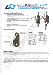
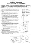
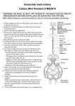
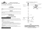
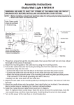
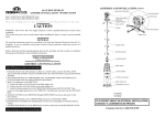
Assembly Instructions
Selby Collection Pendant # PSY067
WARNING: BE SURE TO SHUT OFF POWER AT THE MAIN FUSE OR CIRCUIT
BREAKER BOX BEFORE INSTALLING OR SERVICING THIS FIXTURE.
NOTE: 1. Before installing, consult local electrical codes for wiring and grounding requirements.
2. READ AND SAVE THESE INSTRUCTIONS.
Contents of Spare Parts:
Outlet Box
House Grounding Wire
Wire Nut
Screw
Assembly Kit (1 SET)
(4297MM)
Mounting Strap
Lock Nut
Mounting Screw
1. Thread two screws through the mounting strap, then secure
them with two lock nuts. Adjust the length of the screws if
necessary.
2. Attach the mounting strap to the outlet box by using two
mounting screws.
3. Measure the desired length of the cord (A) from the canopy to
the top end of the cap nut. Leave additional 8" cord (B) above
the canopy, then cut off the unnecessary cord. (See Fig.2)
4. Mark the 3" cord (C) from the top of the cord. Use a knife to peel
off the insulation of the cord (C) carefully to show three inside
wires out. (See Fig.2)
Caution: Cutting too deep may cut off three inside wires and
destroy the insulation surface of the three inside wires.
5. Peel off the three wires from the top at about 5/8" length(D) to
expose the copper for wiring. (See Fig.2)
6. Pull the cord down slightly until the strain relief touches the
inside of the canopy. Then secure the plastic screw. (See Fig.1)
7. Pull out the outlet wires and the house grounding wire from
the outlet box. Make wire connections using the wire nuts:
a. The clear wire marked "L" from the fixture to the black
wire from the power source.
b. The clear wire with white line and marked "N" from the
fixture to the white wire from the power source.
c. The clear grounding wire with green line and marked
" " from the fixture to the green grounding wire from
power source.
Carefully put wires back into the
outlet box.
Cord
8. Attach the canopy to the mounting
strap by inserting the screws, then
Strain Relief
secure it with the ball nuts.
Canopy
9. Install a bulb (not included). Note
relamping label at socket or
packaging area for maximum
allowed wattage.
Cap Nut
Plastic Screw
10. Turn on the power at the main
fuse or circuit breaker box.
Fig.1
Canopy
Plastic Screw
Ball Nut
Cap Nut
Cord
A
Cap Nut
Socket
Shade
Bulb Type B Max.60W
(not included)
D (5/8")
C (3")
B (8")
Cord
Canopy
Fig.2