1
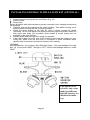
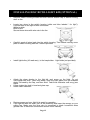
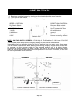
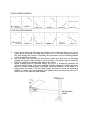
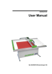
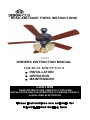
READ AND SAVE THESE INSTRUCTIONS
153791
OWNERS INSTRUCTION MANUAL
FOR DUAL MOUNT FAN’S
INSTALLATION
OPERATION
MAINTENANCE
CAUTION
READ INSTRUCTIONS CAREFULLY FOR SAFE
INSTALLATION AND FAN OPERATION. IF UNSURE CONSULT
A QUALIFIED ELECTRICIAN
These instructions are suitable for
UL/cUL Listed Ceiling fans
TABLE OF CONTENTS
Safety Tips -----------------------------------------------------------------------------------2
Unpacking Your Fan ----------------------------------------------------------------------3
Material Required ---------------------------------------------------------------------------4
Electrical Outlet box------------------------------------------------------------------------4
Install Mounting Bracket------------------------------------------------------------------5
Installing the Fan-----------------------------------------------------------------------------6
Electrical connections----------------------------------------------------------------------9
Blade Attachment---------------------------------------------------------------------------10
Installing Light kit---------------------------------------------------------------------------11
Operation--------------------------------------------------------------------------------------12
Maintenance----------------------------------------------------------------------------------13
Trouble Shooting---------------------------------------------------------------------------14,15
Part List----------------------------------------------------------------------------------------16
Page 1
SAFETY TIPS
TABLE OF CONTENTS
1.
To avoid possible electric shock, turn off the electricity at the main fuse box or
circuit panel before you begin the fan installation or before servicing the fan or
installing accessories.
2. CAUTION: READ ALL INSTRUCTIONS AND SAFETY INFORMATION
CAREFULLY BEFORE INSTALLING YOUR FAN AND SAVE THESE
INSTRUCTIONS.
3. Make sure all electrical connections comply with local codes or ordinances and
the national electrical code. If you are unfamiliar with electrical wiring, please use
a qualified and licensed electrician.
4. Make sure you have a location selected for your fan that allows clear space for
the blades to rotate, and at least seven (7) feet of clearance between the floor
and the fan blade tips. The fan should be mounted at least thirty (30) inches from
walls or other upright structures.
5. WARNING: The outlet box and ceiling support joist used must be securely
mounted, and capable of supporting a minimum of 50 pounds.
6. WARNING: To reduce the risk of fire, electrical shock, or personal injury mount to
outlet box marked” Acceptable For Fan Support” and use mounting screws (and
locked washers) provided with the outlet box.
7. Electrical diagrams are for reference only. Light kits that are not packed with the
fan must be UL listed and marked suitable for use with the model fan you are
installing.
8. After installation is complete, check that all connections are absolutely secured.
9. After making electrical connections, spliced conductors should be turned upward
and pushed carefully up into outlet box. The wires should be turned spread apart
with the grounded conductor and the equipment-grounding conductor on one side
of the outlet box.
10. WARNING: To reduce the risk of fire, electrical shock. Do not use this fan with
any solid-state fan speed control device, or rheostat.
11. Do not insert anything into the fan blades while they are rotating.
12. WARNING: To reduce the risk of personal injury, do not bend the blade brackets
when installing the brackets, balancing the blades, or cleaning the fan. Do not
insert foreign objects in between rotating fan blades.
13. To avoid personal injury or damage to the fan and other items, be cautious when
working around or cleaning the fan.
14. Do not use water or detergents when cleaning the fan or fan blades. A dry dust
cloth or lightly dampened cloth will be suitable for most cleaning.
15. Instructions for supply connections: conductor of a fan identified as grounded
conductor to be connected to a grounded conductor of power supply, conductor of
fan identified as ungrounded conductor to be connected to an ungrounded
conductor of power supply, conductor of fan identified for equipment grounding to
be connected to an equipment-grounding conductor.
NOTE: The important safety precautions and instructions appearing in this manual are
not meant to cover all possible conditions and situations that may occur. It must be
understood that common sense and caution are necessary factors in the installation
and operation of this fan.
CAUTION: To reduce the risk of injury to person, install fan so that the blade is at least
2.1 Meters (7 Feet) above the floor.
Page 2
UNPACKING
SAFETY YOUR
TIPS FAN
1.
2.
Unpack your fan and check the contents. Do not discard the carton. If
warranty replacement or repair is ever necessary the fan should be returned in
original packaging. Remove all parts and hardware. Do not lay motor housing
on its side: the decorative casting may shift.
Examine all parts. You should have the following:
1.
2.
3.
4.
Mounting Bracket
Downrod/Ball assembly
Ceiling canopy
Fan Housing Motor, and switch housing. Remove rubber shipping spacers from
motor. Keep them in case you need to return fan.
5. Set of Blades
6. Blade Arms
7. Light Kit
8. Glass
9. Adaptor
10. Cap
11. Decorative nut
12. Parts Pack Containing:
A/ Mounting bracket hardwares (wire nuts)
B/ Blade attachment hardwares (screws with washers for each blade).
C/ Blade arm attachment hardware (motor screws and lock washers may already
be in fan motor)
D/ Pull chain/Ball
Page 3
TOOLS AND MATERIALS REQUIRED
*Phillips screw driver
*Blade screw driver
*Adjustable pliers or wrench
*Step ladder
*Wire cutter
*Electrical tape
ELECTRICAL OUTLET BOX
1. If there is an existing outlet box, ensure it is clearly marked” Suitable For Fan
Support”. If not, it must be replaced with an approved one.
2. Secure the outlet box (or make sure the existing box is secured) directly to the
building structure. Use appropriate fasteners and building materials. Wood joist
and outlet box must be able to support a minimum of 50 pounds.
3. Figure 1,2 and 3 are examples of different ways to mount the outlet box in different
ways to mount the outlet box in different situations. A longer down rod may be
required in sloped ceiling situations to maintain proper blade clearance.
4. To hang the fan in locations where no ceiling joists is available. A hanger support
bar may be required (Fig. 4)
Outlet Box
Outlet Box
Fig.1
Fig.2
Provide Strong
Support
Recessed
Outlet Box
Ceiling Mounting
Plate
Outlet Box
Fig.3
Fig.4
Page 4
INSTALL MOUNTING BRACKET
1. To avoid possible electrical shock, be sure electricity is turned off at the main
power panel before wiring.
All wiring must be in accordance with National and Local Electrical Codes, and the
ceiling fan must be grounded as a precaution against possible electrical shock.
2. Attach hanger bracket to outlet, box using screws provided with the outlet box
(Fig. 5)
UL LISTED ELECTRICAL
OUTLET BOX
“ACCEPTABLE FOR CEILING FAN ONLY”
HANGER
BRACKET
SPRING WASHER
(PROVIDED WITH OUTLET BOX)
SCREW
(PROVIDED WITH OUTLET BOX)
Page 5
SELECT TYPE OF INSTALLATION
INSTALLING THE FAN
HANG DOWN STYLE
1 Slide the canopy on the downrod(Fig.6) Thread the power leads from the fan
through the canopy and downrod. Take extra care not to pull on power wires. Damage
and loose connections could result from any abnormal pressure on these wires. Set
downrod into downrod collar yoke. Route until the holes match. Being careful not to
damage wiring, insert connector pin through the holes (See Fig. 6A. 6B). Secure the
pin by inserting the stop pin through the connector pin.
Downrod
Power leads
Mounting
Collar Yoke
Connecting
Pin
Ball
Downrod
Fig.6A
Stop Pin
Canopy
Fig.6
Fig.6B
WARNING: Do not force connector pin through downrod. Use of force could cause
damage to wires inside. Make sure the stop pin is properly engaged to prevent it from
falling out.
2 Tighten downrod setscrew. Some models have a locknut for the setscrew. To insure
the setscrew fully seats against the downrod. It is necessary to back off the locknut
until it contact the setscrew head prior to tightened the setscrew. When setscrew is
tightened against downrod.locknut should then be tightened against connector yoke.
Some models have 2 downrod setscrews. Repeat for both (Fig.7)
Page 6
DOWNROD SETSCREW
Lock Nut
Motor Setscrew
Fig.7
3. Tighten motor set screw. Check the strength of this connection (pre-tightened at
factory) by holding the motor housing in position and turning the downrod counter
clockwise. If this connection slips, retighten motor setscrew and locknut. Follow the
same procedures as mentioned above for downrod setscrew.
4. Install ball into hanger bracket opening. The tab opposite of the hanger bracket
opening should fit in slot on ball (Fig 8) .
Hanger Bracket
Tab
Safely Cable(For
cUL_listed fan only)
Ball
Ball Slot
Fig.8
5. Make wire connections (refer to section titled” Electrical Connections”) For
cUL-listed fan, please secure the safety cable to the junction box.
6. Slide canopy up, and fasten to hanger bracket with the 4 screws provided.
WARNING: To avoid damaging the blade arms and blades, do not install either until
fan is fastened to ceiling. To avoid motor shift, handle fan by downrod or switch
housing only.
Page 7
HUGGER STYLE
1. Put 2 screws in the hanger bracket. Leaving them partially out. (Fig. 9.1).
2. Remove three of the six screws and lock washers (every other one) from the top
housing (Fig. 9.2)
3. Place the ceiling canopy over the collar on the top of the motor housing. Align the
mounting holes with the holes in the motor and fasten, using the three screws and
lock washers which are removed in Step 2 (Fig. 9.3)
4. Move the fan assembly up and connect the wires from fan to the wires from ceiling.
(Fig. 9.4)
5. Make wire connections (refer to section titled” ELECTRICAL CONNECTIONS”) For
cUL-listed fan, please secure the safety cable to the junction box.
6. Place the canopy up on the hanger bracket by inserting the slotted opening of the
canopy on the screws. (Fig.9.5)
7. Insert the remaining screws through the remaining canopy holes and tighten all 4
screws.
Screw and
Lockwasher
(3 of 6 places)
Screws
Mounting bracket
Fig.9.1
Fig.9.2
Screw and
Lockwasher
(last 3 places)
Upper
Canopy
Fig.9.3
Fig.9.4
Slotted Hole
Page 8
ELECTRICAL CONNECTIONS
1.
Four wires are connected to the top of the fan.
Black: ” Hot” Power/Live for the fan
Blue: “ Hot” Power/ Live for the light kit
White: “Common”/Neutral for the fan and the light kit
Green/Green & Yellow: “Ground” /Earth wire
4.
Fan controlled by
pull chain switch.
Light controlled by
chain switch on light
BLK
Power lines
120 v
WH
GREEN
GROUND
Light controlled from
wall switch. Fan controlled
by pull chain
Wireing Box
Power lines
120 v
WH
3.
If the fan and light are connected to the same circuit, the black and blue wires
should be connected together to the black wire in the ceiling using a wire nut to
make the connection.
The white wire from the fan should be connected to the white wire in the ceiling,
using a wire nut to make the connection.
The green wire from the fan should be connected to the ground wire in the ceiling,
using a wire nut to make the connection.
BLK
2.
Green
Ground
BLK
Light
Switch
Ground to
mounting
bracket
FAN
BLUE
BLK
FAN
BLUE
BLK
WH
WH
Power lines
120 v
WH
Wireing Box
Green
Ground
BLK
Fan
BLK
Ground to
Downrod on mounting bracket
WH
RED
BLUE
Light
WH
WH
LIGHT
FITTER
LIGHT
FITTER
Fan and light controlled by
independent wall switches.
Ground to
mounting
bracket
WH
RED
BLUE
BLK
WH
BLUE
Wire Box
FAN
BLUE
BLK
WH
WH
LIGHT
FITTER
Page 9
BLADE ATTACHMENT
1.
2.
3.
4.
Place screw through the blade and start the screw into the blade arm repeat this
procedure without tightening the screw until all 3 screws have been started into
the blade arm (Fig.11). As most fan use concealed screw blades arms, screws
may not go through the whole blade arms.
Tighten each screw starting with center screw.
Fasten blade assembly to motor with provided screws. Repeat procedure for
remaining blades. (Fig. 11A)
Make sure the blades are more than /at least 7 feet from the floor, avoid any
object in the path of the blades.
SCREWS
BLADE
BLADE ARM
Fig.11
Attach 4(5 or 6) blade assemblies to motor using the
8(10 or 12) screws provided Make sure all screws are
tightened securely.
Blade assembly
Blade mounting
screws and washers
Fig.11A
Page 10
INSTALLING GENERAL TURTLE LIGHT KIT (OPTIONAL)
1.
2.
Locate two wires in the switch housing (white and blue labeled “ for light”).
Connect them to the light kit wire connectors (Fig. 12)
White to white
Blue to blue
Secure all splices with electrical tape to prevent connectors from vibrating loose during
fan operation.
3. Carefully push all wires back into the switch housing. Then attach housing cover
plate to switch housing with the 3 screws provided.
4. Attach the glass shades to the light kit, using 3 thumb screws per shade
(provided). Do not over-tighten the thumb screws as glass may break. Install (40
watt max). light bulbs (not provided). Glass shade & thumb screws are not
provided on the spot light fan.
5. Restore power and your light kit is ready for operation.
6. If the light kit does not work, turn off the electricity and lower the canopy on your
ceiling fan. Make sure the blue wire is connected to black household wires
(please refer to electrical connections section in this manual).
WARNING:
All suspended fan (not hugger) with 190W light limiter. If the total wattage of the light
bulb (s) is more than 190W, the light is OFF until the total wattage reduce to below
190W.
This light kit is for
reference only, some
model get different
light kit, but they are
installed in similar
way
Page 11
INSTALLING DISC BOWL LIGHT KIT(OPTIONAL)
1.
Remove switch housing screws and then remove bottom cap of switch housing
shell on fan.
2.
Locate two wires in the switch housing (white and blue labeled “ for light”).
Connect them to the light kit wire connectors
White to white
Blue to blue
Secure those wires with wire nuts in the fan.
3.
Carefully push all wires back into the switch housing. Then attach housing cover
plate to switch housing with the 3 screws provided.
4.
Install light bulbs, (40 watt max) , to the lampholder. . Light bulbs (not provided).
5.
Attach the glass shades to the light kit, and screw up the finial. Do not
over-tighten the finial , glass may break. Slide the bowl glass over the threaded
nipple, followed by the cap, and then finial. Twist finial clockwise until snug (see
figure
Lower chains thru hole in bowl and glass cap.
Attach chain extension
6.
7.
8.
9.
Restore power and your light kit is ready for operation.
If the light kit does not work, turn off the electricity and lower the canopy on your
ceiling fan. Make sure the blue wire is connected to black household wires
(please refer to electrical connections section in this manual).
Page 12
OPERATION
1.
2.
3.
Restore electrical power by turning on the electricity at the main fuse box.
Turn on the wall switch.
Your fan has two controls on the switch housing
SPEED CONTROL
Pull Chain Switch
(Tug gently)
Pull Speed
1 High
2 Medium
3 Low
4 Off
Switch Box
DIRECTION CONTROL
Reverse Slide Switch
(Up and down)
Up for upward air flow
to recirculate air
upward
Down for downward air
flow for a cooling effect
NOTE: ON FANS WITH 3 SPEEDS: 1 Pull-High 2. Pull-Medium 3. Pull-Low 4 .Pull-Off
Turn off and let fan stop before changing setting of the reverse slide switch.
Your ceiling fan is a sensible choice to cool as well as help you warm your living area.
You will have a reduction in both heating and cooling costs by regular use of your fan.
In summer, put the reverse switch in the forward position so air is blown down,
producing a cooling breeze. In winter, reverse the fan so an upward airflow will push
warm air off the ceiling and balance the temperature in the room. In winter, run the fan
at lower speed than in the summer.
SUMMER
WINTER
DOWNDRAFT
UPDRAFT
Counter Clockwise Rotation
Counter Clockwise Rotation
Page 13
MAINTENANCE
1.
2.
3.
4.
The fan natural movements may cause some connections to work loose. A
clicking or rattling noise is a certain sign of loosening screws. Check the support
connections, brackets and blade attachment twice a year, and tighten all screws
as necessary. Make sure all screws attaching the glass screws are tightened.
Clean your fan periodically. Use only a cloth dampened with a mild detergent
solution. Never use solvents. Dust with a soft cloth or brush. Metal finishes are
finished with a lacquer to prevent tarnishing.
You will never need to oil your fan. Its permanently sealed bearing will prevent
silent, trouble free operation for many years.
Make sure the power is turned off at the main fuse or circuit panel before you
attempt any repairs.
Page 14
TROUBLE SHOOTING
MAINTENANCE
FAN DOES NOT START
1.
2.
3.
4.
Check all fuses or circuit breakers. Replace if MISSING.
Turn off electrical power and check all wire connections to fan and in switch
housing.
Make sure pull chain switch is on, and reverse slide switch is up or down, not in
the middle.
Unscrew the switch box cover and check all wire connectors, if the wire
connectors are loose, tighten it firmly.
FAN FOUND NOISY
1.
2.
3.
4.
5.
6.
7.
8.
9.
Always takel a few days” break in” time for any new fan at medium or high speed.
Try to diagnose the exact location of the noise by listening carefully from several
sides (blades, motor, light kit, etc). Fan noise can come from a light kit.
Make sure all screws in the fan assembly and light kit are tight and properly
threaded. If not, back out and retighten. Tighten these screws at least once a year
because they may loosen slowly over time and cause clicking noise.
Make sure the light kit is securely fastened to the fan, and all glass screws are
finger tightened only. Do not tighten with pliers or a screwdriver.
Make sure mounting bracket is installed snugly to junction box.
Make sure wire nuts in switch housing or canopy are not rattling against each
other or against wall of housing. Wrap with electrical tape if necessary.
Use of standard light rheostat or unapproved wall control will always cause
harmonic distortions, or a humming noise. Many fan motors do not work quietly
with solid-state variable controls. If a quiet wall control is desired, use only
approved wall controls.
Make sure the canopy is not touching the ceiling.
Assure that the screws fastening blade holders to motor are tight
Make sure all light bulbs are fully screwed in.
FAN TURNS BUT DOES NOT MOVE MUCH AIR
1.
2.
3.
The fan may be running in reverse, so air is directed upward.
The room may contain items that obstruct the airflow.
The fan may be too small for the size of the room.
FAN SHAKES OR WOBBLES
1.
2.
3.
4.
A small amount of wobble is considered acceptable and should not be
considered a defect. Use of any light kit, especially a large 4 or 5 light kit, will
usually induce some wobble.
Make sure mounting bracket is tight at junction box/ceiling with no movement at
all. Tighten screws if necessary.
Make sure all screws holding the blades to the blade arm and blade arm to
motor are tight. Also, make sure light/glass screws are tight
Some fan movement is normal. However, interchanging an adjacent (side by
side) blade pair may redistribute the weight and result in smoother operation, as
next page
Page 15
FOR 4 BLADES MODELS
Numbered tape
placement
Switch 1-2
Switch 3-4
Switch 2-1
Switch 2-4
Switch 4-3
Switch 2-1
Switch 2-4
Switch 4-3
FOR 5 BLADES MODELS
Numbered tape
placement
5.
6.
7.
Switch 2-1
Switch 3-4
If the above does not eliminate the wobble, clip a balancing kit on any one of
blade about the middle of blade edge. Let fan run. If it is still wobbling, stop the
fan, and change the location. Repeating this procedure on the remaining blades
until the wobble is removed.
You can also look up at the fan from below, make sure that none of the blade
holders are bent so that a blade is out of position. Correction may be made by
GENTLY bending the blade holder back into position.
Blade tracking may be checked simply by use of a household yardstick as
shown in below Figure. Place the yardstick vertically against the ceiling and even
with the outside leading edge of a blade. Note the distance of the edge of a
blade same as others. Turn the blade slowly by hand to check the remaining
blades. If a blade us in an alignment, the blade holder may be gently bent up or
down to be in line with the other blades.
YARDSTICK
MEASURING
POINT
Page 16