1
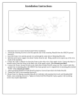
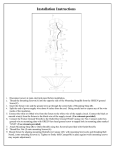
READ AND SAVE THESE INSTRUCTIONS
Hercules - 96SGD
It is highly recommended that a professional install this fan.
Thank you for purchasing a Gulf Coast Fans Inc. product. It will provide
years of cost efficient comfort. With over a decade of experience in
ensuring quality workmanship at an affordable price, we stand behind our
product and we hope you will too.
IMPORTANT PRECAUTIONS
1
Read these instructions carefully before you start.
2
Turn off the power at the source before installation, servicing, or cleaning.
3
WARNING--TO REDUCE THE RISK OF FIRE OR ELECTRIC SHOCK, DO NOT USE
THIS FAN WITH ANY SOLID STATE SPEED CONTROL DEVICE. USE ONLY GULF
COAST CONTROLS.
4
WARNING--TO REDUCE THE RISK OF PERSONAL INJURY, DO NOT BEND THE
BLADE IRONS WHEN INSTALLING ON BLADES, BALANCING THE BLADES, OR
CLEANING THE FAN. DO NOT INSERT FOREIGN OBJECTS IN BETWEEN
ROTATING FAN BLADES.
5
WARNING--TO REDUCE THE RISK OF FIRE, ELECTRIC SHOCK, OR PERSONAL
INJURY, MOUNT FAN TO AN OUTLET BOX MARKED "ACCEPTABLE FOR FAN
SUPPORT" AND USE THE MOUNTING SCREWS PROVIDED WITH THE OUTLET
BOX.
6
If you don't feel comfortable hanging and wiring this fan, we recommend that you hire a
qualified electrician to install it.
7
All wiring and electrical connections must meet the National Electrical Code and any
local codes that may apply.
8
This fan must be mounted on a ceiling at least 10 feet high.
Gulf Coast Fans 2014 - Portions â 1993
Page 1
To begin with, the site of installation must be clear of any obstructions. Walls,
cabinet or cupboard doors, and AC/heating vents (strong air currents will cause
fan to wobble ) are common obstructions.
Also, you will need a securely mounted outlet box that is listed for fan support.
The only tools you will need are: A medium Phillips screwdriver, wire
cutter/stripper, common sense, and a little caution.
I. Inventory the parts
A. Remove all of the parts from the top styrofoam and remove the styrofoam.
Use this top piece to support the fan during preliminary assembly.
Screw Package
2 Wood Screws
2 #8 Machine Screws
2 Spring Washers
2 Star Washers
2 Flat Washers
1 Wood Screws
1 Spring Washers
1 Flat Washers
21 Blade Screws
B. Remove all parts from plastic bags, including the blades,
packaged separately, and screw package.
21 Blade Washers
11 Motor Screws
3 Wirenuts
CANOPY
BOTTOM CUP
Remote Control
Clevis pin
Safety clip
HANGING BRACKET
w/2 CANOPY SCREWS
YOKE COVER
II. Preliminary Assembly.
BALL &
DOWNROD
ASSY
Washer
Transmitter w/9V Battery
BLADE
ARMS
FIG. 1
A. Remove the three (or five) shipping
blocks from the face of the motor
and discard them.
Wall Bracket
2 Bracket Mounting
Screws
REMOVE SHIPPING
BLOCKS (DISCARD)
B. Remove the three (3) 1/8"-32x1/4" screws from the
switch cup plate on motor assembly. Fig. 2.
FIG. 2
SWITCH CUP
SCREWS
C. Place the motor (with the bottom cup mounting plate down) in the top
styrofoam. Loosen the two set screws in the coupler (Fig. 1). If you
are replacing the downrod with a longer one, now is the time to do so.
FIG. 3
D. Feed the wires through the yoke cover, canopy and downrod. Seat the
downrod into the yoke with the holes in each aligned. Insert the clevis pin, and
secure with the washer and safety clip (Fig. 2) Tighten the coupler set screws
against the downrod. Slide the yoke cover down to cover the yoke.
E. At this time you may want to shorten the wires from the fan
to 6" from the ball. This helps when you tuck the wires into
outlet box.
F. Snap the Blade Arm onto the Blade's face that you want to
show. Using four (4) screws and washers per blade, attach
the blade securely to the Blade Arm. Repeat until all five
Blades are assembled onto Blade Arms. (Fig 5)
FIG. 4
FIG. 5
Gulf Coast Fans 2014 - Portions â 1993
Page 2
II. Preliminary Assembly
continued from page 2.
WARNING - To Reduce The Risk Of Fire, Electric Shock, Or Personal
Injury Mount Fan To An Outlet Box Marked "Acceptable For Fan
Support" And Use The Mounting Screws Provided With The Outlet Box.
For the future connection of the safety cable, partially install 1 wood screw, 1 flat washer and 1 spring
washer, leaving 1/8" to 1/4" exposed. Position this screw where it will be covered by the canopy, will
not interfere with the hanging bracket, and is secured into a wood support member. Inside of outlet
box is a common place. See Fig 6.
F. Remove one canopy screw and loosen the other. Take the hanging
bracket and secure it to the outlet box (marked Acceptable For Fan
Support) using the mounting screws provided with the outlet box (Fig 6).
Tighten them evenly. If you are mounting the fan directly to the building
structure, use the wood screws provided, and secure to a joist. Make sure
all of the wires are accessible and are not being pinched. Also, make sure
the bracket doesn't wobble.
Screw for
Safety Cable
Hanging
Bracket
FIG. 6
Expand the loop of the safety cable and place loop over screw head and
under flat washer. Tighten loop of safety cable. Tighten wood screw to
secure safety cable. See Fig 7.
Canopy
Screw
III. Hanging the Fan
FIG. 7
Holding the fan firmly, carefully lift it up to hanging bracket. Place
the ball into cradle of the bracket. Turn the entire motor assembly
until it locks into place. The tab on the bracket must be in the groove
in the ball. Make sure the wires are not being pinched. Also Fig 7.
IV. Wire connections
This fan includes a remote control, and requires basic mains wiring. Keep in mind, the supply wire
colors may vary. (The wire colors in parentheses are commonly found in existing structures.)
Use the large orange wirenuts to make the connections.
FIG. 8
BLACK (from fan)
1. Black wire from fan to hot supply (black)
2. White wire from fan to neutral supply (white)
3. Green ground wires to outlet box ground (bare)
SUPPLY HOT/LIVE
WHITE (from fan)
SUPPLY NEUTRAL
GREEN (from bracket)
GROUND/EARTH
GREEN (from ball)
Now tuck the wires and wirenuts carefully into outlet box. Make sure wirenuts remain tightly on connections.
CANOPY
V.
With the motor in place and the wires out of the way, slide the
canopy up to the hanging bracket. The canopy screw in the bracket
will come through the large end of the key slot in the canopy. Fig. 9.
Turn the canopy slightly, counter-clockwise, to hold in place, and
insert remaining canopy screw. Tighten the screws.
VI. The next step is to mount the blade assemblies on the motor. Rotate
the motor face so that two empty screw holes align with the cut-outs
on the bottom cup mounting plate. Insert one motor screw into one of
the holes in a blade arm's base. Holding the blade assembly in one
hand, place screwdriver tip into screw head to keep screw held in. Lift
blade assembly into place, and screw it into the appropriate hole in the
motor. Fig 10. Now insert another screw into the other hole and
tighten both screws. Repeat this with the rest of the blade assemblies,
and retighten all of the screws.
VII. The final assembly is attaching the bottom cup and it's
easy. If you are adding a light kit, now is the time to attach
it to the switch cup. Lift the cup into place, aligning the
three screw holes in the cup with those on the mounting
plate. Insert one of the screws removed earlier and
thread into switch cup plate. Insert the remaining switch
cup screws and tighten all. Fig. 11.
FIG. 9
Fig. 10
Fig. 11
Gulf Coast Fans 2014 - Portions â 1993
Page 3
DIP
Switches
1
There are 16 possible code frequencies, which are set using the 4 DIP
switches located in the battery compartment of the transmitter. You will
Battery
only need to change the DIP switch settings if you install more than Compartment
one fan in the area, or if you encounter radio frequency interference
from another RF source.
4. Switch on the main power to activate the receiver, indicated by
one beep.
5. Within 3 minutes after the power is turned on (one beep), press
the transmitter's “ON/OFF” key (Fig 13) and do not release
(min. 5 seconds) until receiver issues four beeps which
indicates successful code match.
6. After successful code match, the fan automatically returns to
the original speed as indicated on LCD screen.
7. Press any transmitter button to check for proper
functioning.
8. For code changes, repeat steps 1 to 8.
Fig 12
ON
2
3
4
Press & Hold
9V
BATTERY
VIII. The Remote Control
A. To set the operating frequency and code-match the receiver:
1. Remove the battery cover from the back of the transmitter.
2. Install 9V Battery
3. Set the code using the DIP switches of transmitter. Fig 12.
Battery Cover
Fig 13
B. There are 5 buttons and the function of each button is described below. The receiver will beep for
each function triggered by the push of a button on the transmitter.
1
1. SPEED?: This button is to switch the fan speed from high to low. There
2
are 6 speeds in total.
Note: When the fan is off, we can start the fan by pushing this button.
Choose your speed according to the LCD.
3
2. SPEED : This button is to switch the fan speed from low to high.
There are 6 speeds in total. When set to the highest speed, the LCD
4
5
display will show "MAX".
Note: When the fan is off, we can start the fan by pushing this button.
Choose your speed according to the LCD.
Fig 14
3. FAN/OFF : When the fan is "OFF", push this button to start the fan.
When the fan is "ON", push this button to turn it off.
?
4. FOR/REV: This is a forward/reverse direction button. Press this button to
change from forward to reverse or from reverse to forward.
When the fan is running counter-clockwise (looking up at it), the airflow is downward, which is
recommended for best efficiency and for summertime. Clockwise rotation gives upward airflow for
gentle circulation suitable for winter.
5. LIGHT: This is an on/off button for light. Push this button to turn on and turn off the light.
If you are using incandescent bulbs, a dimming cycle can be used by pressing and holding this
button. (Dimming function is not suitable for CFL or LED lamps.)
C. Memory Function: This control has memory function. When the power is turned off, the control will
automatically record the last fan and light mode. Next time when the fan is turned on, the control will
automatically set to the previous fan speed and brightness.
IX.
Troubleshooting
Fan
Check power supply.
won't
Check wirenut connections.
run Re-set remote frequency code.
Fan
Allow 24 hrs to fully seat bearings
makes Screw(s) is(are) loose somewhere.
noise - Ball is not seated properly.
Solid-state control in the circuit.
Fan
Bracket is loose at the ceiling.
wobbles Loose screw at top of fan.
Ball is not seated properly.
We stand behind our product and
always strive to satisfy our customer.
Gulf Coast Fans, Inc.
300Dunbar Ave
Oldsmar Florida 34677
(813)-855-7384
Gulf Coast Fans 2014 - Portions â 1993
Page 4