1
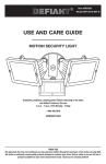
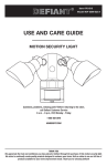
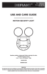
Item #997389
Model #DF-5311-BZ-D
USE AND CARE GUIDE
MOTION SECURITY LIGHT
Questions, problems, missing parts? Before returning to the store,
call Defiant Customer Service
8 a.m. - 6 p.m., EST, Monday - Friday
1-866-308-3976
HOMEDEPOT.COM
THANK YOU
We appreciate the trust and confidence you have placed in Defiant through the purchase of this motion security light.
We strive to continually create quality products designed to enhance your home. Visit us online to see our full line of
products available for your home improvement needs. Thank you for choosing Defiant!
Table of Contents
Tools Required .......................................3
Hardware Included.................................4
Package Contents ..................................5
Mounting Locations ...............................5
Installation ................................................6
Operation...................................................8
Care and Cleaning ..................................11
Troubleshooting ......................................11
Table of Contents ......................................2
Safety Information ....................................2
Precautions ............................................2
Warranty ...................................................2
2-Year Warranty .....................................2
Specifications ...........................................3
Pre-Installation .........................................3
Planning Installation ..............................3
Safety Information
PRECAUTIONS
WARNING: Turn the power off at the circuit breaker or
fuse. Place tape over the circuit breaker switch and verify
power is off at the light fixture.
Please read and understand this entire manual before
attempting to assemble, install, or operate this light
fixture.
WARNING: Risk of fire. Do not aim the bulb at a
combustible surface within 3 ft. (1 m).
This light fixture requires 120-volts AC.
Some codes require installation by a qualified electrician.
This light fixture must be properly grounded.
WARNING: Risk of fire. Keep the bulb at least 2 in.
(51 mm) from combustible materials.
This light fixture is intended for use with the enclosed
gasket and with a junction box marked for use in wet
locations.
WARNING: Risk of fire. This fixture is designed for wall
mounting only. DO NOT install on a ceiling or soffit.
Use a clean glove or cloth when handling the new bulb.
Use isopropyl (rubbing) alchohol to clean the bulb if it is
touched with bare hands.
CAUTION: Keep the motion sensor at least 1 in. (25 mm)
away from the bulb.
For proper operation, this light fixture should be:
Ƒ
Installed outdoors to a wall
CAUTION: To avoid water damage and the risk of
electrical shock, the motion sensor controls must be facing
the ground when the installation is complete.
Ƒ
Installed 8 ft. (2.4 m) above the ground (If the light
fixture is mounted higher than recommended,
aiming the sensor down will reduce the coverage
area.)
CAUTION: Burn hazard. Allow the light fixture and the
bulb to cool before touching.
Ƒ
Do not leave the “ON-TIME” switch in the “TEST”
position. The frequent ON/OFF cycling of the light
fixture will reduce the life of the bulb
Ƒ
Use only T3 500W (maximum), tungsten halogen
bulb (120 VAC)
CAUTION: Do not cut any wires with factory installed
wire connectors or remove the wire connectors.
NOTICE: Do not connect this light fixture to a dimmer switch or
timer.
NOTE: The bulb is included, but needs to be installed. The
bulb is located behind the glass cover of the lamp head.
Warranty
2-YEAR WARRANTY
Contact the Customer Service Team at 1-866-308-3976 or visit www.homedepot.com.
2
Specifications
Range
Up to 70 ft. (21.3 m) - Varies with surrounding temperature
Sensing angle
Up to 270°
Electrical load - incandescent
Up to 500 watt maximum
Power requirements
120 VAC, 60 Hz
Operating modes
Test, Auto, Manual
Time delay
1, 5, 20 minutes
Replacement bulb
T3 500W, halogen 120 VAC
Pre-Installation
PLANNING INSTALLATION
Before installing the light fixture, ensure that all parts are present (see Hardware Included on page 4). If any part is
missing or damaged, do not attempt to assemble, install, or operate this light fixture.
Estimated installation time: 30 minutes
TOOLS REQUIRED
Phillips
screwdriver
Flathead
screwdriver
Pliers
Wire strippers/
cutters
Circuit tester
Work gloves
Electrical tape
Silicone sealant
Ladder
Safety goggles
Drill
3/16” (5 mm)
Drill bit
3
HOMEDEPOT.com
Please contact 1-866-308-3976 for further assistance.
Pre-Installation (continued)
HARDWARE INCLUDED
NOTE: Hardware shown to actual size.
AA
BB
CC
DD
FF
EE
GG
Part
Description
AA
Wire connector
Quantity
3
BB
Bolt
1
CC
Mounting bracket screw
2
DD
Mounting bracket screw
2
EE
Mounting bracket screw
2
FF
Gasket (not to scale)
1
GG
T3 halogen bulb (not to scale)
1
4
Pre-Installation (continued)
PACKAGE CONTENTS
A
B
C
Part
Description
Quantity
A
Bulb holder
1
B
Canopy
1
C
Motion sensor
1
MOUNTING LOCATIONS
Ƒ
Determine the mounting location.
Ƒ
Position bulb holder (A) in the general direction
of the desired light coverage and tighten the lock
nut (1) and the screw (2).
Ƒ
If needed, lift the motion sensor (C) up and
rotate it so the controls face the ground after
installation. Tighten the clamp screw (3) when
done. Do not overtighten.
Wall Mount
A
2
1
NOTE: If the motion sensor (C) pops out of the ball joint,
loosen the clamp screw (3), push the motion sensor (C)
back into the ball joint, and tighten the clamp screw (3). Do
not overtighten.
C
3
5
HOMEDEPOT.com
Please contact 1-866-308-3976 for further assistance.
Installation
Bulb Holder to
2 Attaching
Fixture Arm
1 Drilling Canopy Holes
Ƒ
WARNING: Turn the power off at the circuit breaker or
fuse. Place tape over the circuit breaker switch and verify
power is off at the light fixture.
Ƒ
Ƒ
Ƒ
Remove the existing light fixture.
Determine which of the knockouts need to
be used to match the mounting holes on the
junction box.
If needed, drill the necessary holes into the
canopy (B) using a drill (not included) and a
3/16” (5 mm) drill bit (not included).
Ƒ
Pull the bulb holder (A) wires through the
canopy (B) while placing the bulb holder (A)
and fixture arm (3) together. Make sure none of
the wires are pinched between the two pieces.
Make sure the gasket (4) is properly placed
between the bulb holder (A) and fixture arm (3)
and secure with bolt (BB).
A
BB
4
3
B
B
3 Wiring the Light Fixture
4 Mounting the Light Fixture
Ƒ
CAUTION: Do not cut any wires with factory installed
wire connectors or remove the wire connectors.
Ƒ
Ƒ
Ƒ
Route the light fixture wires through the large
hole in the gasket (FF).
Connect the light fixture wires to the junction
box wires with wire connectors (AA):
Ƒ White to white
Ƒ
Black to black
Ƒ
Bare or green ground wire to house ground
Align the drilled holes on the canopy (B) with
the holes on the junction box.
Secure the canopy (B) to the junction box using
the mounting screws (CC, DD, or EE) that best
fit the junction box. Do not overtighten.
NOTE: Make sure all the wires are inside the junction box
before attaching the canopy (B) to the junction box.
B
AA
CC, DD, or EE
AA
6
Installation (continued)
Around the Light
5 Caulking
Fixture
Ƒ
Caulk around the canopy (B) and mounting
surface with silicone sealant (not included).
B
and Replacing the
6 Installing
Bulb
9
A
1
5
5
CAUTION: Burn hazard. Allow the light fixture and the
bulb to cool before touching.
NOTICE: Use two hands when removing the glass cover. The glass
cover is only being held in place by the glass retaining clips.
8
2
7
NOTE: The bulb is included, but needs to be installed. The
bulb is located behind the glass cover of the lamp head.
6
GG
Use a clean glove or cloth when handling the new
bulb. Use isopropyl (rubbing) alchohol to clean the bulb
if it is touched with bare hands.
Ƒ
Ƒ
Ƒ
Ƒ
Ƒ
While holding the glass cover (6) with one
hand, unlatch the glass retaining clips (5).
Remove the glass cover (6).
Remove the bulb (GG) from the box.
Place one end of the bulb (GG) on the contact
in the right bulb socket (7). While pushing the
bulb (GG) against the contact, lower the other
end of the bulb (GG) onto the contact in the
left bulb socket (8). The bulb (GG) should spin
easily if it is seated properly.
Make sure the gasket (9) is seated properly
in the groove around the edge of the bulb
holder (A). Center the glass cover (6) on the
bulb holder (A) and secure using the retaining
clips (5).
To remove the bulb (GG), push the bulb (GG) to
the right until the left side of the bulb (GG) is
clear of the left bulb socket (8).
7
HOMEDEPOT.com
Please contact 1-866-308-3976 for further assistance.
Operation
Sensor Controls
2 Rotating
Downward
1 Adjusting the Bulb Holder
CAUTION: To avoid water damage and risk of electrical
shock, the motion sensor controls must be facing the
ground when installation is complete.
WARNING: Risk of fire. Do not aim the bulb at a
combustible surface within 3 ft. (1 m).
Ƒ
WARNING: Risk of fire. Keep the bulb at least 2 in.
(51 mm) from combustible materials.
Rotate the motion sensor (C) so the controls
face toward the ground.
NOTICE: All clearances must be maintained. See Safety Information
on page 2.
CAUTION: Burn hazard. Allow the light fixture and the
bulb to cool before touching.
CAUTION: Keep the sensor at least 1 in. (25 mm) away
from the bulb.
CAUTION: Keep bulb holder 30° below horizontal to
avoid water damage and electrical shock.
Ƒ
Ƒ
Ƒ
C
Turn the power on at the circuit breaker or fuse
and turn on the wall switch.
Loosen the lock nut (1) and screw (2) to
adjust the bulb holder (A) for the desired light
coverage. Make sure the bulb holder (A) is
horizontal after all adjustments have been
made.
Tighten the lock nut (1) and screw (2).
NOTE: Do not rotate the bulb holder more than 180° from
the factory setting.
NOTE: The halogen light must be mounted horizontally
(+/- 4°).
1
2
A
A
CORRECT
INCORRECT
8
Operation (continued)
the Motion Sensor
3 Setting the Sensor for Testing 4 Adjusting
Detection Zone
Ƒ
When the “ON-TIME” switch is set to the “TEST”
position, the light fixture will operate during the day
or night. The light will stay on for 5 seconds after all
motion is stopped.
Ƒ
Ƒ
Ƒ
Ƒ
Ƒ
Set the “ON-TIME” switch to the “TEST”
position.
Turn the “RANGE” dial to the “MIN” position.
Aim the motion sensor (C) in the general
direction of the area to be covered.
Ƒ
Ƒ
NOTE: The motion sensor will need to completely warm
up (90 seconds) before beginning the setup process.
Ƒ
Turn on the circuit breaker or fuse and the light
switch.
Perform a “walk test”. Walk in an arc across
the front of the motion sensor (C).
Watch the light. The light will come on when
motion has been detected.
Stop, wait for the light to turn off, and then
begin walking again.
Continue this process until the detection zone
has been established.
Adjust the sensor up, down, or side to side to
change the motion sensor (C) detection zone.
C
RANGE
MIN
MAX
TEST 1 5 20
MINUTES
ON-TIME
C
5 Adjusting the RANGE Dial
Ƒ
Ƒ
C
To increase the detection zone, turn the
“RANGE” dial toward the “MAX” position.
To decrease the detection zone, turn the
“RANGE” dial toward the “MIN” position.
RANGE
NOTE: The motion sensor (C) is more sensitive to motion
moving across the front of the sensor. The motion sensor
(C) is less sensitive to motion moving directly toward the
front of the sensor.
MIN
MAX
NOTE: The higher the “RANGE” setting (sensitivity), the
greater the possibility of false triggering. To reduce false
triggering, rotate the “RANGE” control toward the “MIN”
setting.
9
HOMEDEPOT.com
Please contact 1-866-308-3976 for further assistance.
Operation (continued)
6 Adjusting the ON-TIME Switch 7 Using Manual Mode
The “ON-TIME” switch determines the amount of time
the light will stay on full bright after all motion has
stopped.
Ƒ
Manual mode overrides the motion sensor (C) and
“ON-TIME” control so the light will operate full bright.
This feature only works at night and only for one night
at a time. The motion sensor (C) will reset to motion
sensing mode after 6 hours or sunrise, whichever
comes first. Manual mode can be toggled on and off
using a wall switch.
Set the “ON-TIME” switch to the 1, 5, or 20
minute position.
Ƒ
C
Ƒ
TEST 1 5 20
MINUTES
To turn manual mode on, switch the light off
at the wall switch for 3 to 4 seconds and then
back on.
To turn manual mode off, switch the light off
at the wall switch for 3 to 4 seconds and then
back on.
NOTE: If the power to the light fixture is off for more than
5 seconds, allow the motion sensor to warm up prior to
switching to manual mode.
ON-TIME
Turn the switch
OFF for 3 to 4
seconds
10
Turn the
switch
back ON
Care and Cleaning
Ƒ
To prolong the original appearance, clean with clear water and a soft, damp cloth only.
Ƒ
Do not use paints, solvents, or other chemicals on this light fixture. They could cause a premature
deterioration of the finish. This is not a defect in the finish and will not be covered by the warranty.
Ƒ
Do not spray with a hose or power washer.
Troubleshooting
Problem
The light will not come on.
The light comes on during the
day.
The light comes on for no
apparent reason.
Possible Cause
Solution
Ƒ
The light switch is turned off.
Ƒ
Turn the light switch on.
Ƒ
The bulb is loose or burned out.
Ƒ
Check the bulb and replace
if burned out.
Ƒ
The fuse is blown or the circuit breaker
is turned off.
Ƒ
Replace the fuse or turn the
circuit breaker on.
Ƒ
Daylight turn-off (photocell) is in effect.
Ƒ
Recheck after dark.
Ƒ
The circuit wiring is incorrect, if this is
a new installation.
Ƒ
Verify the wiring is correct.
Ƒ
The motion sensor is aimed in the
wrong direction.
Ƒ
Re-aim the motion sensor
to cover the desired area.
Ƒ
The outside air temperature is close to
the same as a person’s body heat.
Ƒ
Increase the “RANGE”
setting.
Ƒ
The motion sensor may be installed in a
relatively dark location.
Ƒ
The light fixture is operating normally under these
circumstances.
Ƒ
The “ON-TIME” switch is in the “TEST”
position.
Ƒ
Set the “ON-TIME” switch
to the 1, 5, or 20 minute
setting.
Ƒ
The motion sensor may be sensing
small animals or automobile traffic.
Ƒ
Re-aim the motion sensor.
Ƒ
The “RANGE” dial is set too high.
Ƒ
Decrease the “RANGE”
setting.
Ƒ
The outside temperature is much
warmer or cooler than a person’s body
heat (summer or winter).
Ƒ
Decrease the “RANGE”
setting.
Ƒ
The light fixture is wired through a
dimmer or timer.
Ƒ
Do not use a dimmer or
timer to control the light
fixture. Replace the dimmer
or timer with a standard on/
off wall switch.
11
HOMEDEPOT.com
Please contact 1-866-308-3976 for further assistance.
Troubleshooting (continued)
Problem
The light stays on continuously.
The light flashes on and off.
The light flashes once then stay
off in manual mode.
Possible Cause
Solution
Ƒ
The bulb is positioned too close to the
motion sensor or pointed at nearby
objects that cause heat to trigger the
motion sensor.
Ƒ
Reposition the bulb away
from the motion sensor or
nearby objects.
Ƒ
The motion sensor may be picking up
a heat source like an air vent, dryer
vent, or brightly painted, heat-reflective
surface.
Ƒ
Decrease the “RANGE”
setting or reposition the
motion sensor.
Ƒ
The motion sensor is in manual mode.
Ƒ
Switch the motion sensor
to auto. See Using Manual
Mode on page 10.
Ƒ
The light fixture is wired through a
dimmer or timer.
Ƒ
Do not use a dimmer or
timer to control the light
fixture. Replace the dimmer
or timer with a standard on/
off wall switch.
Ƒ
The light fixture is on the same circuit
as a motor, transformer, or fluorescent
bulb.
Ƒ
Install the light fixture on
a circuit without motors,
transformers, or fluorescent
bulbs.
Ƒ
Heat or light from the bulb may be turning the motion sensor on and off.
Ƒ
Reposition the bulb away
from the motion sensor.
Ƒ
Heat is being reflected from other
objects and may be turning the motion
sensor on and off.
Ƒ
Reposition the motion
sensor.
Ƒ
The motion sensor is in “TEST” mode
and warming up.
Ƒ
Flashing is normal under
these conditions.
The motion sensor is detecting light from
the bulb.
12
Reposition the bulb to keep the
area below the motion sensor
relatively dark.
13
HOMEDEPOT.com
Please contact 1-866-308-3976 for further assistance.
Questions, problems, missing parts? Before returning to the store,
call Defiant Customer Service
8 a.m.-6 p.m., EST, Monday-Friday
1-866-308-3976
HOMEDEPOT.COM
Retain this manual for future use.
205295-04A
Articulo #997389
Modelo #DF-5311-BZ-D
GUÍA PARA EL USO Y CUIDADO
LUZ DE SEGURIDAD POR MOVIMIENTO
¿Tiene preguntas, problemas o piezas perdidas? Antes de la devolución al
almacén llame a Servicio al Cliente de Defiant
8 a.m.- 6 p.m., Hora del Este, de lunes a viernes
1-866-308-3976
HOMEDEPOT.COM
GRACIAS
Agradecemos la fe y la confianza que usted ha depositado en Defiant al comprar esta luz de seguridad por
movimiento. Procuramos crear continuamente productos de calidad diseñados para mejorar su hogar. Visítenos en
internet para ver nuestra línea completa de productos disponibles que necesita para el mejoramiento de su hogar.
¡Gracias por escoger Defiant!
Contenido
Herramientas Requeridas ....................16
Ferretería Incluida................................17
Contenido del Paquete .........................18
Sitios Para el Montaje ..........................18
Instalación ..............................................19
Operación ...............................................21
Cuidado y limpieza .................................24
Análisis de averías .................................24
Contenido ................................................15
Información de seguridad ......................15
Precauciones .......................................15
Garantía...................................................15
2 Años de Garantía ...............................15
Especificaciones .....................................16
Antes de la instalación ...........................16
Planificación de la Instalación .............16
Información de seguridad
PRECAUCIONES
Por favor lea y entienda todo este manual antes de tratar
de ensamblar, instalar u operar este aparato de luz.
Este aparato de luz requiere 120 voltios CA.
ADVERTENCIA: Desconecte la energía eléctrica en el
disyuntor o en el fusible. Coloque cinta aislante sobre el
interruptor disyuntor y compruebe que no haya energía
eléctrica en el aparato de luz.
ADVERTENCIA: Riesgo de incendio. No enfoque la
bombilla a una superficie combustible que esté hasta a
3 pies (1 m).
Algunos códigos exigen que la instalación la realice un
electricista calificado.
Este aparato de luz debe estar correctamente conectado
a tierra.
ADVERTENCIA: Riesgo de incendio. Mantenga la
bombilla alejadas al menos 2 pulgadas (51mm) de
materiales combustibles.
Este aparato de luz está concebido para usarlo con el
empaque adjunto y con una caja de conexiones indicada
para uso en sitios húmedos.
ADVERTENCIA: Riesgo de incendio. Este aparato de luz
está diseñado para montarse solamente en una pared. NO
lo instale en el techo o en el cielo raso.
Use un guante o un paño limpio cuando manipule la
bombilla nueva. Use alcohol isopropílico para limpiar la
bombilla si la toca con las manos desprotegidas.
PRECAUCIÓN: Mantenga el detector de movimiento al
menos a 1 pulgada (25mm) alejado de la bombilla.
Para que opere correctamente, este aparato de luz debe ser:
Ƒ
Instalado en el exterior en una pared.
Ƒ
Instalado a 8 pies (2,4m) por encima del suelo
(Si el aparato de luz es montado más arriba de lo
recomendado, al enfocar el detector hacia abajo se
reducirá el área de cobertura)
Ƒ
Ƒ
PRECAUCIÓN: Para evitar daños por el agua y el
riesgo de una descarga eléctrica, los controles del detector
de movimiento deben estar de cara al suelo cuando la
instalación esté terminada.
PRECAUCIÓN: Peligro de quemaduras. Deje que el
aparato de luz y la bombilla se enfríen antes de tocarlos.
No deje el interruptor de “DURACIÓN” (“ON-TIME”)
en la posición “PRUEBA” (“TEST”). La alternancia
frecuente entre ENCENDIDO/APAGADO (ON/OFF)
reducirá la vida de la bombilla.
PRECAUCIÓN: No corte ningún cable conductor que
tengan capuchones para cable instalados de fábrica ni
retire estos capuchones.
Use solamente la bombilla halógena de tungsteno
T3 de 500 W (máximo) y (120 VCA)
AVISO: No conecte este aparato de luz a un interruptor reductor de
luz ni a un temporizador.
NOTA: La bombilla está incluida, pero necesita ser
instalada. La bombilla está detrás de la tapa de vidrio del
cabezal de lámpara.
Garantía
2 AÑOS DE GARANTÍA
Póngase en contacto con el personal de servicio al cliente al 1-866-308-3976 o visite el sitio www.homedepot.com.
16
Especificaciones
Alcance
Hasta 70 pies (21,3 m) – Varía con la temperatura circundante
Ángulo de detección
Hasta 270°
Carga eléctrica-Incandescente
Hasta 500 vatios máximo
Requisitos de la energía eléctrica
120 VCA, 60 Hz
Fases de operación
Prueba, automática, manual
Retardo de tiempo
1, 5, 20 minutos
Bombilla de recambio
T3 de 500W, halógena 120 VCA
Antes de la instalación
PLANIFICACIÓN DE LA INSTALACIÓN
Antes de instalar el aparato de luz, esté seguro que estén todas las piezas (vea Ferretería incluida en la página 17).
Si cualquier pieza falta o está dañada, no intente ensamblar, instalar ni operar este aparato de luz.
Tiempo estimado para la instalación: 30 minutos
HERRAMIENTAS REQUERIDAS
Destornillador
phillips
Destornillador
plano
Alicates
Peladores/
cortadores de
cables
Probador de
circuitos
Guantes de
trabajo
Cinta aislante
Sellador de
silicona
Escalera
Gafas de
seguridad
Taladro
Broca de 3/16
de pulgada
(5 mm)
17
HOMEDEPOT.com
Por favor, póngase en contacto al 1-866-308-3976 para obtener más ayuda.
Antes de la instalación (continuación)
FERRETERÍA INCLUIDA
NOTA: La ferretería se muestra en su tamaño real
AA
BB
CC
DD
EE
FF
Pieza
GG
Descripción
Cantidad
AA
Capuchón para cable
3
BB
Perno
1
CC
Tornillo del soporte de montaje
2
DD
Tornillo del soporte de montaje
2
EE
Tornillo del soporte de montaje
2
FF
Empaque (no está a escala)
1
GG
Bombilla halógena T3 (no está a escala)
1
18
Antes de la instalación (continuación)
CONTENIDO DEL PAQUETE
A
B
C
Pieza
Descripción
Cantidad
A
Porta bombilla
1
B
Escudete
1
C
Detector de movimiento
1
SITIOS PARA EL MONTAJE
Ƒ
Determine el sitio para el montaje.
Ƒ
Coloque el porta bombillas (A) en la dirección
general para la cobertura de luz deseada y
apriete la contratuerca (1) y el tornillo (2).
Ƒ
Si es necesario, levante el detector de
movimiento (C) y gírelo de forma que los
controles queden de cara al suelo luego de
la instalación. Apriete el tornillo sujetador (3)
cuando se provea. No apriete demasiado.
Montaje en
pared
A
2
1
C
3
NOTA: Si el detector de movimiento (C) se sale de la
unión esférica, afloje el tornillo sujetador (3), empuje de
nuevo el detector de movimiento (C) hacia la unión esférica
y apriete el tornillo sujetador (3). No apriete en exceso.
19
HOMEDEPOT.com
Por favor, póngase en contacto al 1-866-308-3976 para obtener más ayuda.
Instalación
de los agujeros del
1 Taladro
escudete
del porta bombillas al
2 Sujeción
brazo del aparato de luz
Ƒ
ADVERTENCIA: Desconecte la energía eléctrica en el
disyuntor o en el fusible. Coloque cinta aislante sobre el
interruptor disyuntor y compruebe que no haya energía
eléctrica en el aparato de luz.
Ƒ
Ƒ
Ƒ
Retire el aparato de luz existente.
Determine cuales discos removibles necesitan
ser usados para que coincidan con los
agujeros de montaje de la caja de conexiones.
Si es necesario, taladre los agujeros
necesarios en el escudete (B) con un taladro
(no incluido) y una broca de 3/16 de pulgada
(5mm) (no incluida).
Ƒ
Hale los cables del porta bombillas (A) a
través del escudete (B) mientras une entre si
el porta bombillas (A) y el brazo del aparato de
luz (3). Esté seguro que ningún cable quede
remordido entre las dos piezas.
Esté seguro que el empaque (4) esté
correctamente colocado entre el porta
bombillas (A) y el brazo del aparato de luz (3) y
asegurado con el perno (BB).
A
BB
4
3
B
B
3 Cableado del aparato de luz 4 Montaje del aparato de luz
Ƒ
PRECAUCIÓN: No corte ningún cable conductor que
tengan capuchones de cable instalados de fábrica ni retire
estos capuchones.
Ƒ
Ƒ
Ƒ
Pase los cables del aparato de luz a través del
agujero grande en la junta (FF).
Conecte los cables del aparato de luz a los
cables de la caja de conexiones con los
capuchones para cables (AA):
Ƒ Blanco con blanco
Ƒ
Negro con negro
Ƒ
Cable de conexión a tierra desnudo o
verde con la conexión a tierra doméstica
Alinee los agujeros perforados en el escudete
(B) con los orificios de la caja de conexiones.
Asegure el escudete (B) a la caja de
conexiones con los tornillos de montaje (CC,
DD o EE) que mejor se ajusten a la caja de
conexiones. No apriete excesivamente.
NOTA: Esté seguro que todos los alambres estén dentro
de la caja de conexiones antes de acoplar el escudete (B) a
la caja de conexiones.
B
AA
CC, DD, or EE
AA
AA
20
Instalación (continuación)
alrededor del aparato
5 Calafatee
de luz
Ƒ
Calafatee alrededor del escudete (B) y en
la superficie de montaje con un sellador de
silicona (no incluido)..
B
y recambio de la
6 Instalación
bombilla
9
A
1
5
5
PRECAUCIÓN: Peligro de quemaduras. Deje que el
aparato de luz y la bombilla se enfríen antes de tocarlos.
AVISO: Use ambas manos cuando retire la tapa de vidrio. La tapa
de vidrio se sostiene en su sitio solamente mediante las presillas de
retención del vidrio.
8
NOTA: La bombilla está incluida, pero necesita ser
instalada. La bombilla está ubicada detrás de la tapa de
vidrio del cabezal de la lámpara.
6
2
7
GG
Use un guante o un paño limpio cuando manipule la
nueva bombilla. Use alcohol isopropílico para limpiar
la bombilla si la toca con las manos desprotegidas.
Ƒ
Ƒ
Ƒ
Ƒ
Ƒ
Mientras sostiene la tapa de vidrio (6) con una
mano, desenganche las presillas de retención
del vidrio (5). Retire la tapa de vidrio (6).
Retire la bombilla (GG) de la caja.
Coloque un extremo de la bombilla (GG) sobre
el contacto del zócalo derecho de la bombilla
(7). Mientras empuja la bombilla (GG) contra el
contacto, baje el otro extremo de la bombilla
(GG) sobre el contacto del zócalo izquierdo (8)
de la bombilla. La bombilla (GG) debería girar
con facilidad si es asentada correctamente.
Asegúrese de que el empaque (9) esté
asentado correctamente en la ranura que
rodea el borde del porta bombillas (A). Centre
la tapa de vidrio (6) en el porta bombillas (A)
y asegúrela con las presillas de retención del
vidrio (5).
Para retirar la bombilla (GG), empuje la
bombilla (GG) a la derecha hasta que el lado
izquierdo de la bombilla (GG) esté libre del
zócalo izquierdo (8) de la bombilla.
21
HOMEDEPOT.com
Por favor, póngase en contacto al 1-866-308-3976 para obtener más ayuda.
Operación
hacia abajo de los
1 Regulación del porta bombillas 2 Giro
controles del detector
ADVERTENCIA: Riesgo de incendio. No enfoque la
bombilla a una superficie combustible que esté hasta a
3 pies (1 m).
PRECAUCIÓN: Para evitar daños por el agua y el
riesgo de una descarga eléctrica, los controles del detector
de movimiento deben estar de cara al suelo cuando la
instalación esté terminada.
ADVERTENCIA: Riesgo de incendio. Mantenga la
bombilla alejadas al menos 2 pulgadas (51mm) de
materiales combustibles.
Ƒ
Gire el detector de movimiento (C) de manera
que los controles estén orientados hacia suelo.
AVISO: Todos los espacios libres deben ser mantenidos. Vea
Información sobre seguridad en la página 15.
PRECAUCIÓN: Peligro de quemaduras. Deje que el
aparato de luz y la bombilla se enfríen antes de tocarlos.
PRECAUCIÓN: Mantenga el detector de movimiento al
menos a 1 pulgada (25mm) alejado de la bombilla.
PRECAUCIÓN: Mantenga el porta bombillas a 30° por
debajo de la línea horizontal para evitar daños por el agua
y una descarga eléctrica.
Ƒ
Ƒ
Ƒ
Conecte la energía eléctrica en el disyuntor o en
el fusible y encienda el interruptor de la pared.
Afloje la contratuerca (1) y el tornillo (2) para
regular el porta bombillas (A) para la cobertura
de luz deseada. Esté seguro que el porta
bombillas (A) quede horizontal luego de haber
realizado todos los ajustes.
Apriete la contratuerca (1) y el tornillo (2).
C
NOTA: No gire el porta bombillas más de 180° del ajuste
hecho en fábrica.
NOTA: La luz halógena debe ser montada
horizontalmente (+/- 4°).
1
2
A
A
CORRECTO
INCORRECTO
22
Operación (continuación)
del detector para
de la zona de
3 Calibración
4 Regulación
prueba
detección del detector de
movimiento
Cuando el interruptor de “DURACIÓN” (“ON-TIME”) se
fija en la posición “PRUEBA” (“TEST”) el aparato de luz
operará durante el día o la noche. La luz permanecerá
encendida 5 segundos después que todo movimiento
se ha detenido.
Ƒ
Ƒ
Ƒ
Fije el interruptor de “DURACIÓN” en la
posición “PRUEBA (“TEST”).
Gire el cuadrante “ALCANCE” (“RANGE”) a la
posición “MIN”.
Enfoque el detector de movimiento (C) en la
dirección general del área a ser cubierta.
Ƒ
Ƒ
Ƒ
Ƒ
Ƒ
NOTA: El detector de movimiento necesitará calentarse
completamente (90 segundos) antes de empezar el
proceso de puesta a punto.
Ƒ
C
Conecte el disyuntor o el fusible y el
interruptor de la lámpara.
Haga una “prueba caminando”. Camine
transversalmente a la parte frontal del detector de
movimiento (C) siguiendo la trayectoria de un arco.
Observe la luz. La luz se encenderá cuando el
movimiento es detectado.
Deténgase, espere que la luz se apague, y
luego empiece a caminar de nuevo.
Continúe este proceso hasta que la zona de
detección haya sido establecida.
Ajuste el detector hacia arriba, abajo, o a los
lados para cambiar la zona de detección del
detector de movimiento (C).
RANGE
MIN
MAX
TEST 1 5 20
MINUTES
ON-TIME
C
5
Ƒ
Ƒ
Regulación del cuadrante
ALCANCE (RANGE)
C
Para aumentar la zona de detección, gire el
cuadrante “ALCANCE” (“RANGE”) hacia la
posición “MÁX”.
Para disminuir la zona de detección, gire el
cuadrante “ALCANCE” (“RANGE”) hacia la
posición “MÍN”
RANGE
MIN
MAX
NOTA: El detector de movimiento (C) es más sensible al
movimiento transversal a la parte frontal del detector. El
detector de movimiento (C) es menos sensible al movimiento
que se dirige directamente hacia la parte frontal del detector.
NOTA: Mientras mayor sea la calibración del “ALCANCE”
(“RANGE”) (sensibilidad), mayor será la posibilidad de
falsas alarmas. Para reducir las falsas alarmas, gire el
control del “ALCANCE” (“RANGE”) hacia la calibración
“MÍN”.
23
HOMEDEPOT.com
Por favor, póngase en contacto al 1-866-308-3976 para obtener más ayuda.
Operación (continuación)
del interruptor de
6 Regulación
7 Uso del la fase manual
DURACIÓN
La fase manual anula el detector de movimiento (C) y
el control de duración (“ON-TIME”), de esta forma la
lámpara operará con todo su brillo. Esta característica
funciona solamente en la noche y solamente una noche
a la vez. El detector de movimiento (C) se reiniciará en
la modalidad de detección de movimiento después de
6 horas o cuando salga el sol, lo que ocurra primero. La
fase manual puede también alternar entre encendido y
apagado mediante el interruptor de pared.
El interruptor de DURACIÓN determina el lapso de
tiempo que la luz permanece encendida con todo su
brillo luego que ha cesado el movimiento.
Ƒ
Coloque el interruptor de DURACIÓN en la
posición 1, 5 o 20 minutos.
C
Ƒ
Ƒ
TEST 1 5 20
MINUTES
ON-TIME
Para encender la fase manual, apague la
luz con el interruptor de pared entre 3 a 4
segundos y luego vuelva a encenderla.
Para apagar la fase manual, apague la luz con
el interruptor de pared entre 3 a 4 segundos y
luego vuelva a encenderla.
NOTA: Si la energía eléctrica al aparato de luz es
apagada por más de 5 segundos, deje que el detector de
movimiento se caliente antes del cambio a la fase manual.
Apague el
interruptor
entre 3 a 4
segundos
24
Vuelva a
encender el
interruptor
Cuidado y limpieza
Ƒ
Para mantener la apariencia original, limpie solamente con agua limpia y un paño húmedo y suave.
Ƒ
No use pinturas, solventes ni otros químicos en este aparato de luz. Podrían ser la causa de una prematura
deterioración del acabado. Esto no es un defecto del acabado y no será cubierto por la garantía.
Ƒ
No rocíe con manguera ni con una lavadora eléctrica.
Análisis de averías
Problema
La lámpara no se enciende.
La luz se enciende durante el
día.
La luz se enciende sin razón
aparente.
Causa Probable
Solución
Ƒ
El interruptor de la luz está apagado.
Ƒ
Encienda el interruptor de
la luz.
Ƒ
La bombilla está floja o quemada.
Ƒ
Revise la bombilla y cámbiela si está quemada.
Ƒ
El fusible está quemado o el disyuntor
está desconectado.
Ƒ
Cambie el fusible o conecte
el disyuntor.
Ƒ
El apagado de la luz diurna (fotocélula)
está vigente.
Ƒ
Vuelva a revisar al amanecer.
Ƒ
El cableado del circuito es incorrecto, si
esta es una instalación nueva.
Ƒ
Verifique que el cableado
esté correcto.
Ƒ
El detector de movimiento está enfocando a la dirección incorrecta.
Ƒ
Vuelva a enfocar el detector
de movimiento para que
cubra el área deseada.
Ƒ
La temperatura del aire exterior está
cercana al calor corporal de una
persona.
Ƒ
Aumente la calibración del
alcance (“RANGE”).
Ƒ
El detector de movimiento puede estar
instalado en un sitio relativamente
oscuro.
Ƒ
El aparato de luz está operando normalmente bajo
estas circunstancias.
Ƒ
El interruptor de duración (“ON-TIME”)
está en la posición prueba (“TEST”).
Ƒ
Coloque el interruptor de
duración (“ON-TIME”) en
la calibración 1, 5 o 20
minutos.
Ƒ
El detector de movimiento puede estar
detectando pequeños animales o
tráfico automotor.
Ƒ
Vuelva a enfocar al detector
de movimiento.
Ƒ
El cuadrante alcance (“RANGE”) está
calibrado demasiado alto.
Ƒ
Reduzca la calibración del
alcance (“RANGE”).
Ƒ
La temperatura exterior está más
caliente o más fría que el calor corporal
de una persona (verano o invierno).
Ƒ
Reduzca la calibración del
alcance (“RANGE”).
Ƒ
El aparato de luz está cableado a
través de un reductor de luz o de un
temporizador.
Ƒ
No use un reductor de luz
o un temporizador para
controlar el aparato de luz.
Cambie el reductor de luz o
el temporizador por un interruptor de pared estándar
de encendido/apagado.
25
HOMEDEPOT.com
Por favor, póngase en contacto al 1-866-308-3976 para obtener más ayuda.
Análisis de averías (continuación)
Problema
La luz queda encendida
continuamente.
La luz destella encendiéndose y
apagándose.
La luz destella una vez, luego se
apaga en la fase manual.
Causa Probable
Solución
Ƒ
La bombilla está colocada demasiado
cerca del detector de movimiento o
apuntando a objetos cercanos que
generan calor y activan el detector de
movimiento.
Ƒ
Reposition the bulb away
from the motion sensor or
nearby objects.
Ƒ
El detector de movimiento puede estar
absorbiendo calor de una fuente de
calor como una ventosa de aire, una
secadora de aire, o una superficie
pintada con colores brillantes y que
refleja el calor.
Ƒ
Reduzca la calibración del
alcance (“RANGE”) o vuelva
a colocar el detector de
movimiento.
Ƒ
El detector de movimiento está en la
fase manual.
Ƒ
Cambie el detector de
movimiento a automático.
Vea Uso de la fase manual
en la página 23.
Ƒ
El aparato de luz está cableado a
través de un reductor de luz o de un
temporizador.
Ƒ
No use un reductor de luz
o un temporizador para
controlar el aparato de luz.
Cambie el reductor de luz o
el temporizador por un interruptor de pared estándar
de encendido/apagado.
Ƒ
El aparato de luz está en el mismo
circuito que un motor, transformador o
tubo fluorescente.
Ƒ
Instale el aparato de luz
en un circuito sin motores,
transformadores o tubos
fluorescentes.
Ƒ
El calor o la luz de la bombilla puede
estar encendiendo o apagando al
detector de movimiento.
Ƒ
Vuelva a colocar la bombilla
alejada del detector de
movimiento.
Ƒ
El calor reflejado desde otro objeto
puede estar encendiendo y apagando
al detector de movimiento.
Ƒ
Vuelva a colocar el detector
de movimiento.
Ƒ
El detector de movimiento está en la
fase “TEST” (PRUEBA) y calentándose.
Ƒ
El prenderse y apagarse
es normal bajo estas
condiciones.
El detector de movimiento está detectando
la luz de la bombilla.
26
Vuelva a colocar la bombilla
para mantener el área debajo
del detector de movimiento
relativamente oscura.
27
HOMEDEPOT.com
Por favor, póngase en contacto al 1-866-308-3976 para obtener más ayuda.
¿Tiene preguntas, problemas o piezas faltantes? Antes de la devolución al almacén llame al
Servicio al Cliente de Defiant de
8 a.m.-6 p.m., Hora del Este, de lunes a viernes.
1-866-308-3976
HOMEDEPOT.COM
Guarde este manual para uso futuro.
205295-04A