1
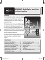
Español
XTRA SMART TM Wireless Weather Sensor System
Installation and Setup Guide
Introduction
The XTRA SMARTTM Wireless Weather Sensor system is designed
exclusively for your Toro EC.XTRATM indoor model timer to
continuously monitor and adjust automatic watering to suit
current watering needs.
The Wireless Sensor system consists of a remote Weather Sensor
that detects current sunlight level, temperature and rainfall,
then transmits this information wirelessly to the Smart PodTM
plugged into the EC·XTRA timer. The Smart Pod then adjusts the
running time to provide the optimum amount of water required
for the next scheduled sprinkler operation.
To familiarize yourself with XTRA SMART Weather Sensor system,
take just a few moments to read through this guide in
its entirety.
Wireless
Weather Sensor
Smart Pod
TM
Table of Contents
Weather Sensor Feature Overview............................... 2
Smart Pod Feature Overview.......................................... 3
Scheduling Advisor and Smart Pod Setup................ 4–5
Weather Sensor System Installation............................ 6
Pairing the Smart Pod and Weather Sensor............. 6
Adjusting the Rain Sensor Threshold.......................... 6
Installing the Weather Sensor........................................ 6–7
Weather Sensor Doc Rev A.indd 1
Weather Sensor System Operations.............................. 8
Battery Service Information.............................................. 9
Warranty Information.......................................................... 10
FCC Information..................................................................... 10
Specifications.......................................................................... 11
Smart Pod Indicator Reference Table............................ 12
12/23/10 3:44 PM
Weather Sensor Feature Overview
1. Rain Sensor Test Pin
Pressing the test pin simulates operation of
the Rain Sensor by transmitting a signal to
the Smart Pod.
1
3
2
4
5
2. Rain Sensor Adjustment Cap
The Rain Sensor sensitivity is adjustable to
suspend watering at 1/8”, 1/4”,, 1/2” and 3/4”
(3 mm, 6 mm, 12 mm and 19 mm) of
accumulated rainfall.
3. Solar Collector
Solar radiation and temperature are used
by the Smart Pod to calculate and adjust
watering to suit current weather conditions.
4. Battery Compartment
A 9V Alkaline battery (installed) can provide
Weather Sensor operation up to five years.
Note: See battery service information on
page 9 for additional information.
6
5.QuickClipTM Mounting Bracket
The QuickClipTM bracket design enables the
Weather Sensor to be easily installed and
aligned.
6.Antenna
2
Weather Sensor Doc Rev A.indd 2
12/23/10 3:44 PM
Smart Pod Feature Overview
1. Antenna
2.EC·XTRA Timer Connector
The Smart Pod is connected securely to the EC·XTRA timer
by inserting the connector plug into the special receiver port,
located on the right (facing) side of the timer housing.
1
2
3. Enter Button
Pressing the Enter button transfers the watering schedule,
downloaded to the Smart Pod from the Scheduling AdvisorTM
PC program, to the EC·XTRA timer. In addition, the sensor
bypass mode is toggled On and Off with the Enter button.
3
4. LED Indicators
All Weather Sensor system functions and status conditions
are identifiable through various operating combinations of the
and green
indicators.
red
4
5
Note: See the Smart Pod Indicator Reference Table provided on
page 12 for detailed information.
To Computer
USB Port
5. USB Cable – The provided USB cable is used to transfer the
custom watering schedule, created in the Scheduling AdvisorTM
PC program, to the Smart Pod.
3
Weather Sensor Doc Rev A.indd 3
12/23/10 3:44 PM
Scheduling Advisor and Smart Pod Setup
Note: Prior to installing and testing the Weather Sensor system, the Scheduling AdvisorTM program must be
downloaded from www.ecxtra.com, installed and running on your PC.
1. On the EC·XTRA web page, locate the Download New
Scheduling Advisor box in the lower left corner, then
click Learn More to begin the download process.
2. Install the Scheduling Advisor program on your PC
as prompted by the Installer Wizard.
will be placed on the Windows
3. A shortcut icon
desktop during program installation. Click on the icon to
open the Scheduling Advisor program.
4. When the program opens, select the New Schedule
option. The Scheduling Advisor will guide you through
the watering schedule setup process.
Important: Entering your ZIP code is required, as it directs
the Scheduling Advisor to retrieve historic weather data from
the internet for your specific ZIP code area.
Based on the data collected, the Scheduling Advisor
generates a default watering schedule tailored for the highest
water demand rate expected for the year.
The Weather Sensor system then continuously monitors
and adjusts the watering run time to suit current weather
conditions and watering demand.
Note: Due to variables associated with internet connectivity,
the Scheduling Advisor may require multiple attempts to
access and retrieve the required weather data.
4
Weather Sensor Doc Rev A.indd 4
12/23/10 3:44 PM
5. When your watering schedule has been completed, the
file will be automatically saved to the PC hard disk.
6. Connect the Smart Pod to the PC using the provided
USB cable.
Note: The USB connection to the Smart Pod is confirmed
indicator is On. The Scheduling Advisor
when the green
displays Smart Pod Recognized, and switches
the Pod symbol from black to green.
7. Click on Send Schedule to begin transferring the
watering schedule to the Smart Pod. The green
indicator will blink rapidly during the transfer process.
8. A confirmation box will be displayed when the transfer
process has been successfully completed. Click OK to
continue, then disconnect the USB cable.
9. With the EC·XTRA control dial in the RUN position,
carefully plug the Smart Pod into the timer receptacle
and green
indicators will
as shown. The red
blink in unison.
10.Press and release the ENTER button to begin transferring the watering schedule to the EC·XTRA. The green
indicator will blink momentarily, and the timer will
display donE when the transfer process is complete.
Important: The ENTER button must be pressed within two minutes of the initial Smart Pod/EC·XTRA
connection to accomplish the watering schedule transfer. If the two-minute period elapses without pressing the
ENTER button, remove the Smart Pod, then repeat steps 9 and 10 above.
5
Weather Sensor Doc Rev A.indd 5
12/23/10 3:44 PM
Pairing the Smart Pod and Weather Sensor
Note: The Smart Pod must be initially paired (matched) to the Weather Sensor to enable wireless communication.
The pairing process helps prevent the Smart Pod from receiving unwanted signals from other wireless devices
operating within the system reception range.
and green
indicators blink alternately.
1. Press and hold the Smart Pod ENTER button until the red
2. Press the Rain Sensor test pin to signal to the Smart Pod. Signal reception and pairing is confirmed when the
red
indicator responds with a sequence of rapid blinking with intermittent On and Off.
Adjusting the Rain Sensor Threshold
The Rain Sensor is preset to suspend watering at 1/4” (6 mm) of accumulated rainfall. Three alternate settings
of 1/8” (3 mm), 1/2” (12 mm) and 3/4” (19 mm) are provided. Prior to installing the Weather Sensor, adjust the
threshold to the preferred setting as required.
Note: Increasing the threshold setting results in extending the length of
timer required for the sensor to shut off or postpone watering during rain,
as well as extending the dry-out period before scheduled watering will
resume. In areas where heavy fog or mist is common, the 1/8” (3 mm)
setting may not provide accurate rain detection, and is not recommended.
1/4” (6.4mm)
1. Turn the cap slightly, releasing it from the two retaining pins.
2. Adjust the cap to engage the pins at the preferred slot setting.
1/2” (13mm)
Installing the Weather Sensor
Important: The Weather Sensor must have full exposure to sun, wind and rain, and must not be installed inside a
rain gutter, or in any location where immersion, runoff, or contact with irrigation spray will occur. Avoid installation
near a heat source, such as a heater vent or chimney. Also avoid installation near any large metal structure or high
current-draw equipment that may generate signal interference. Ensure the antenna wire hangs unobstructed below
the Weather Sensor.
6
Weather Sensor Doc Rev A.indd 6
12/23/10 3:44 PM
Note: The communication range of the Wireless Weather Sensor system is 500’ (152 m) LOS (line of sight). Some loss
of range can be expected due to interference from obstacles in the signal path. Test the signal reception from the
proposed installation site prior to mounting the Weather Sensor, as described in the following procedure.
1. Start a manual watering operation for a zone that can be seen from the proposed Weather Sensor
location. Press and hold the Rain Sensor test pin to send a signal to the Smart Pod. If the signal is received,
watering should shut off within a short time. If not, repeat the test from a slightly different location, until
communication is established.
2.(A) For rain gutter installation: back
the bracket thumbscrew out to clear
the rain gutter edge. Holding the
Weather Sensor in position, tighten
the thumbscrew securely.
(B) For solid structure installation:
remove the thumbscrew and secure
the bracket using the provided
stainless screws (or other appropriate
stainless fasteners).
A
B
3. With the mounting bracket securely fastened, check the vertical alignment of the Weather Sensor. To adjust,
loosen the phillips screw at the bracket joint, adjust to vertical, then tighten the screw securely.
7
Weather Sensor Doc Rev A.indd 7
12/23/10 3:44 PM
Weather Sensor System Operations
The XTRA Smart Weather Sensor system provides two important elements of weather information to the
EC·XTRA timer: Rain/Freeze Hold, and Watering Schedule Management.
• Rain/Freeze Sensor Feature
The Rain/Freeze sensor signals the Smart Pod to suspend automatic watering when
it has detected a specified amount of rainfall, or the temperature drops to nearindicator will be On while automatic watering is suspended,
freezing. The red
and turn Off when the automatic watering schedule resumes.
Note: To bypass the Rain/Freeze sensor function while watering is suspended, press
indicator will begin
the ENTER button to select the Sensor Bypass mode. The red
blinking, and watering operation will resume as scheduled. To return to sensor-controlled
operation, press the ENTER button again.
Important: Freeze sensors should always be used in conjunction with visual checks of the sprinkler system. While
the Weather Sensor is designed to postpone watering when air temperature is detected near freezing, watering can
still occur under certain conditions. For example, the air temperature may rise above the sensor shut-off point, while
the temperature of the landscape and walkways remains below freezing. Or, a drop in air temperature may occur so
rapidly, the sensor is unable to suspend scheduled watering in time. Watering in these conditions can result in icing!
• Watering Schedule Management Feature
The EC·XTRA watering schedule is managed by the Weather Sensor system by
continuously monitoring key weather conditions, and sending this information
to the Smart Pod/EC·XTRA. The watering run time duration is evaluated and
automatically adjusted up or down according to the current demand for irrigation.
When an adjustment occurs, the percent symbol (%) is visible in the timer display.
Note: To view the actual % adjustment value, turn the EC·XTRA dial to Season Adjust.
Refer to the EC·XTRA User’s Guide for detailed Season Adjust feature information.
8
Weather Sensor Doc Rev A.indd 8
12/23/10 3:44 PM
Battery Service Information
In normal operating conditions, the Weather Sensor battery can last up to five years. A weak battery
condition is indicated if the Smart Pod’s green
indicator begins blinking slowly at a steady rate. A loss of
communication can result from a weak battery condition, and is indicated when the green
indicator
is Off with an intermittent flash.
• Replacing the Battery
1. The battery is stored in the upper half of the
sensor housing. To access the battery, release
and remove the upper housing by twisting it
clockwise.
2. Disconnect the battery wire clip. Remove and
replace the used battery with a fresh 9V Alkaline battery. Reconnect the battery wire clip.
3. To reassemble the sensor housing, thread the
antenna wire through the lower housing, exiting the center hole in the bottom grid.
4. Mate the two halves squarely, aligning the
translucent dome above the mounting
bracket.
5. Turn the upper housing counterclockwise to
securely engage the lower housing.
Note: Properly discard the used battery as
prescribed by the battery manufacturer.
9V
9
Weather Sensor Doc Rev A.indd 9
12/23/10 3:44 PM
Warranty Information
The Toro Company and its affiliate, Toro Warranty Company, pursuant to an agreement between them, jointly warrants, to the
owner, against defects in material and workmanship for a period of one year from the date of purchase.
Neither The Toro Company nor Toro Warranty Company is liable for failure of products not manufactured by them even though such
products may be sold or used in conjunction with Toro products.
During such warranty period, we will repair or replace, at our option, any part found to be defective.
Return the defective part to the place of purchase.
Our liability is limited solely to the replacement or repair of defective parts. There are no other express warranties.
This warranty does not apply where equipment is used, or installation is performed, in any manner contrary to Toro’s specifications
and instructions, nor where equipment is altered or modified.
Neither The Toro Company nor Toro Warranty Company is liable for indirect, incidental or consequential damages in connection
with the use of equipment, including but not limited to: vegetation loss, the cost of substitute equipment or services required during
periods of malfunction or resulting non-use, property damage or personal injury resulting from installer’s negligence.
Some states do not allow the exclusion or limitation of incidental or consequential damages, so the above limitation or exclusion may
not apply to you.
All implied warranties, including those of merchantability and fitness for use, are limited to the duration of this express warranty.
Some states do not allow limitations of how long an implied warranty lasts, so the above limitation may not apply to you. This
warranty gives you specific legal rights and you may have other rights which vary from state to state.
FCC Information: This equipment generates and uses radio frequency energy and if not installed and used properly, that is, in strict accordance with the
manufacturer’s instructions, may cause interference to radio and television reception. It has been type tested and found to comply with the limits for a FCC
Class B computing device in accordance with the specifications in Subpart J of Part 15 of FCC Rules, which are designed to provide reasonable protection
against such interference in a residential installation. However, there is no guarantee that interference will not occur in a particular installation. If this equipment does cause interference to radio or television reception, which can be determined by turning the equipment off and on, the user is encouraged to try to
correct the interference by one or more of the following measures:
• Reorient the receiving antenna
• Relocate the irrigation controller with respect to the receiver
• Move the irrigation controller away from the receiver
• Plug the irrigation controller into a different outlet so that the irrigation controller and receiver are on different branch circuits.
If necessary, the user should consult the dealer or an experienced radio/television technician for additional suggestions. The user may find the following
booklet prepared by the Federal Communications Commission helpful: “How to Identify and Resolve Radio-TV Interference Problems.”This booklet is
available from the U.S. Government Printing Office, Washington, DC 20402. Stock No. 004-000-00345-4 International: This is a CISPR 22 Class B product.
Weather Sensor: FCC ID: OF7WS9 • IC ID (Canada): 3575A-WS9
Smart Pod: FCC ID: OF7SP9 • IC ID (Canada): 3575A-SP9
10
Weather Sensor Doc Rev A.indd 10
12/23/10 3:44 PM
Specifications
Smart Pod:
• 1.5” (3,8 cm) W x 4.75” (12 cm) H (over 2” [5,1 cm] antenna) x 0.75” (1,9 cm) D
• Mini USB cable receptacle
• Operating temperature range: 14° – 104° F ( -10°– 40°C)
Weather Sensor:
• 2.75” (7 cm) W x 7” (17,8 cm) H (over 2” [5 cm] antenna) x 6.25” (15,9 cm) D (over 4” [10,2 cm] mounting bracket)
• 9V Alkaline battery
• RF reception range: 500’ (152 m) LOS (line of sight)
• Operating temperature range: 14° – 140° F ( -10°– 60°C)
PC System Requirements (minimum):
•*Windows® 2000, Vista, XP or Windows® 7
• Microsoft® .Net 3.5 Framework
• USB 1.0 Port
• 900 MHz, Intel® or Pentium® Processor
• 64 MB RAM
• 200 MB Free Disk Space
• 1024 x 768 16-bit Color Monitor
• Windows-supported pointing device (e.g. mouse)
• Internet access
*Windows® and Microsoft® are registered trademarks of the Microsoft® Corporation in the United States and/or other countries.
Intel® and Pentium® are registered trademarks of the Intel Corporation in the United States and or/other countries.
11
Weather Sensor Doc Rev A.indd 11
12/23/10 3:44 PM
Smart Pod Indicator Reference Table
Red
Off
Off
Off
Blinking
Off
Blinking
Blinking (rapidly)
Off
On
Blinking
On
Off
Blinking
Green
Off
On
On
Blinking (in unison with Red)
Blinking (rapidly)
Blinking (rapidly)
On
Off (with intermittent flash)
On
On
Blinking
Blinking
Blinking (alternately with Red)
Weather Sensor System Status
Smart Pod not connected
Smart Pod connected to computer USB
Smart Pod connected to timer - normal mode
Smart Pod in data transfer mode – press ENTER button
Smart Pod transferring watering schedule to timer
Smart Pod in pairing mode – press Rain Sensor test pin
Smart Pod receiving signal from weather sensor
Smart Pod lost communication with weather sensor
Rain/Freeze Sensor On – watering suspended
Rain/Freeze Sensor On - sensor in bypass mode
Low battery condition – watering suspended
Low battery condition – normal mode
Low battery condition – sensor in bypass mode
The Toro Dedication to Quality
Toro is committed to developing and producing the highest quality, best performing, most dependable products
on the market. Because your satisfaction is our first priority, we have provided the Toro Helpline to assist you with
any questions or problems that may arise. If for some reason you are not satisfied with your purchase or have
questions, please contact us toll free at 1-800-367-8676.
© 2010 The Toro Company • www.toro.com
12
Weather Sensor Doc Rev A.indd 12
Form Number 373-0592 Rev. A
12/23/10 3:44 PM
Español
Sensor meteorológico inalámbrico XTRA SMARTTM
Guía de instalación y configuración
Introducción
El Sensor meteorológico inalámbrico XTRA SMART™ ha sido diseñado
exclusivamente para su temporizador de interiores Toro EC·XTRA™.
Monitoriza y ajusta constantemente el sistema de riego automático
según las necesidades de cada momento.
El sistema consta de un sensor meteorológico remoto que detecta
el nivel de luz solar directa, la temperatura y la lluvia y transmite
esta información de forma inalámbrica al Smart Pod™ conectado al
temporizador EC·XTRA. El Smart Pod luego ajusta el tiempo de riego,
a fin de proporcionar la cantidad óptima de agua para la siguiente
operación de riego programado.
Sensor meteorológico
inalámbrico
Smart Pod™
Para familiarizarse con el sistema meteorológico XTRA SMART, tome
unos momentos para leer esta guía en su totalidad.
Tabla de contenidos
Características del Sensor meteorológico............................. 2
Características del Smart Pod...................................................... 3
Configuración de Scheduling Advisor y Smart Pod........... 4–5
Instalación del Sensor meteorológico..................................... 6
Emparejado del Smart Pod y el Sensor meteorológico... 6
Ajuste del umbral del Sensor de lluvia.................................... 6
Instalación del Sensor meteorológico..................................... 6–7
Weather Sensor Spa.indd 1
Operaciones del Sensor meteorológico................................... 8
Información sobre la pila................................................................. 9
Información sobre la garantía....................................................... 10
Información FCC.................................................................................. 10
Especificaciones.................................................................................. 11
Indicadores del Smart Pod – Tabla de consulta..................... 12
12/23/10 3:44 PM
Características del Sensor meteorológico
1. Pulsador de prueba del Sensor de lluvia
El pulsador de prueba simula el funcionamiento
del Sensor de lluvia transmitiendo una señal al
Smart Pod.
2. Tapón de ajuste del Sensor de lluvia
La sensibilidad del Sensor de lluvia es ajustable, y
permite suspender el riego a diferentes niveles de
lluvia acumulada – 3 mm, 6 mm, 12 mm y 19 mm
(1/8", 1/4",, 1/2" y 3/4").
1
3
2
4
6
5
3. Colector solar
El Smart Pod utiliza la radiación solar y la
temperatura para calcular y ajustar el riego según
las condiciones meteorológicas actuales.
4. Compartimento de la pila
Una pila alcalina de 9 V (instalada) proporciona la
alimentación del Sensor meteorológico durante
hasta cinco años.
Nota: Para más información, consulte
Mantenimiento de la pila en la página 9.
5. Soporte de montaje QuickClip™
El diseño especial del soporte QuickClip™
facilita la instalación y la alineación del Sensor
meteorológico.
6.Antena
2
Weather Sensor Spa.indd 2
12/23/10 3:44 PM
Características del Smart Pod
1. Antena
2. Conector para el temporizador EC·XTRA
El Smart Pod se conecta firmemente al temporizador EC·XTRA
introduciendo el conector en el enchufe especial situado en el lado
derecho de la carcasa del temporizador.
1
2
3
3. Tecla Enter
Cuando se pulsa la tecla Enter, se transfiere el calendario de riego,
descargado al Smart Pod desde el programa Scheduling Advisor™,
al temporizador EC·XTRA. La tecla Enter también sirve para activar y
desactivar el modo de anulación del sensor.
4. Indicadores LED
Todas las funciones y condiciones de estado del Sensor
meteorológico pueden identificarse mediante diversas
combinaciones de los indicadores rojo
y verde
.
4
Nota: La Tabla de consulta de indicadores LED del Smart Pod de la
contraportada contiene información detallada al respecto.
5
5. Cable USB — El cable USB suministrado se utiliza para transferir
el calendario de riego personalizado, creado por el programa
Scheduling Advisor™, al Smart Pod.
Al puerto USB de
la computadora
3
Weather Sensor Spa.indd 3
12/23/10 3:44 PM
Configuración de Scheduling Advisor y Smart Pod
Nota: Antes de instalar y probar el Sensor meteorológico, es necesario descargar el programa Scheduling Advisor™ de
www.ecxtra.com, e instalarlo y ejecutarlo en su PC.
1. En la página web de EC·XTRA, localice el recuadro Download
New Scheduling Advisor (descargar nuevo Scheduling
Advisor) en la esquina inferior izquierda, luego haga clic en
Learn more (Saber más) para iniciar el proceso de descarga.
2. Instale el programa Scheduling Advisor en su PC siguiendo
las instrucciones del Asistente de instalación.
3. Se colocará un icono de acceso directo
en el escritorio de
Windows durante la instalación del programa. Haga clic en el
icono para abrir el programa Scheduling Advisor.
4. Cuando el programa se abra, seleccione la opción New
Schedule (Calendario nuevo). Scheduling Advisor le guiará
a través del proceso de configuración del calendario de riego.
Importante: Es necesario introducir su código ZIP, para
que Scheduling Advisor pueda recuperar de Internet datos
meteorológicos históricos sobre la región específica de su
código ZIP. Dependiendo de los datos recopilados,
Scheduling Advisor genera un calendario de riego
predeterminado calibrado según la mayor demanda de agua
prevista para el año. El Sensor meteorológico luego monitoriza
y ajusta constantemente el tiempo de riego dependiendo de
las condiciones meteorológicas y la demanda de riego en cada
momento.
Nota: Debido a variaciones de conectividad a Internet,
Scheduling Advisor puede necesitar varios intentos para localizar
y recuperar los datos meteorológicos necesarios.
4
Weather Sensor Spa.indd 4
12/23/10 3:44 PM
5. Una vez creado su programa de riego, el archivo se
guardará automáticamente en el disco duro de su PC.
6. Conecte el Smart Pod a la PC usando el cable USB
suministrado.
Nota: La conexión USB al Smart Pod queda confirmada
cuando se enciende el indicador verde
. Scheduling Advisor
muestra el mensaje Smart Pod Recognized (Smart Pod
reconocido), y cambia los símbolos del Pod de negro a verde.
7. Haga clic en Send Schedule (Enviar calendario) para
empezar a transferir el calendario de riego al Smart Pod.
El indicador verde
parpadeará rápidamente durante
el proceso de transferencia.
8. Se mostrará un mensaje de confirmación cuando el proceso
de transmisión se haya completado con éxito. Haga clic en
OK para continuar, luego desconecte el cable USB.
9. Con el dial de control del EC·XTRA en la posición de RUN
(Marcha), enchufe cuidadosamente el Smart Pod en el
conector del temporizador, según se indica. Parpadearán
al unísono los indicadores rojo
y verde
.
10.Pulse y suelte la tecla ENTER para empezar a transferir
el calendario de riego al EC·XTRA. El indicador verde
parpadeará momentáneamente y el temporizador
mostrará donE (Terminado) cuando se termine el proceso
de transferencia.
Importante: Es imprescindible pulsar la tecla Enter en menos de dos minutos después de conectar el Smart Pod al
EC·XTRA para poder realizar la transferencia del calendario de riego. Si el periodo de dos minutos finaliza sin haberse pulsado
la tecla ENTER, retire el Smart Pod y repita los pasos 9 y 10 anteriores.
5
Weather Sensor Spa.indd 5
12/23/10 3:44 PM
Emparejado del Smart Pod y el Sensor meteorológico
Nota: Es necesario emparejar inicialmente el Smart Pod con el Sensor meteorológico para habilitar la comunicación
inalámbrica. El proceso de emparejado ayuda a impedir que el Smart Pod reciba señales indeseadas de otros dispositivos
inalámbricos que se encuentren dentro del alcance de recepción del sistema.
1. Pulse y mantenga pulsado el botón ENTER del Smart Pod hasta que parpadeen de forma alternativa los indicadores
rojo
y verde
.
2. Pulse el pulsador de prueba del Sensor de lluvia para enviar una señal al Smart Pod. La recepción de la señal y el
emparejado quedan confirmados cuando el indicador rojo
responda con una secuencia de parpadeos rápidos,
encendiéndose y apagándose de forma intermitente.
Ajuste del umbral del Sensor de lluvia
El ajuste predeterminado del Sensor de lluvia es suspender el riego al alcanzar 1/4" (6 mm) de precipitación acumulada.
Tiene 3 ajustes alternativos, de 3 mm (1/8"), 12 mm (1/2") y 19 mm (3/4"). Antes de instalar el Sensor meteorológico,
modifique el umbral si es preciso.
Nota: Si se aumenta el umbral, se extiende el tiempo necesario para que el sensor
apague o suspenda el riego durante la lluvia, además de extender el periodo de
secado antes de reanudar el riego programado. En zonas donde acostumbra
3mm
3mm
6mm
a haber niebla o bruma espesa, es posible que el ajuste de 3 mm (1/8") no permita
6mm
12mm
19mm
la detección precisa de la lluvia, y no se recomienda utilizarlo.
1. Gire el tapón ligeramente para liberarlo de las dos clavijas de retención.
6 mm (1/4")
13 mm (1/2")
2. Mueva el tapón para introducir las clavijas en la ranura del ajuste
deseado.
Instalación del Sensor meteorológico
Importante: El Sensor meteorológico debe estar totalmente expuesto al sol, al viento y a la lluvia, y no debe instalarse dentro
de un canalón o en un lugar donde pueda quedar expuesto a inmersión, escorrentía, o contacto con el agua de riego pulverizada.
Evite instalarlo cerca de una fuente de calor, como chimeneas o conductos de ventilación de calentadores. Evite también su
instalación cerca de grandes estructuras metálicas o equipos con alto consumo eléctrico que pueden generar interferencias en las
señales. Asegúrese de que el cable de la antena cuelga sin obstrucciones por debajo del Sensor meteorológico.
6
Weather Sensor Spa.indd 6
12/23/10 3:44 PM
Nota: El alcance de las comunicaciones del Sensor meteorológico inalámbrico es de 152 m (500') en línea visual directa.
Es normal que se produzca alguna merma en el alcance debido a interferencias causadas por obstáculos en el camino de la
señal. Pruebe la recepción de la señal desde el lugar de instalación previsto antes de montar el Sensor meteorológico, según
se describe en el procedimiento siguiente.
1. Inicie el riego manual en una zona que pueda verse desde el lugar previsto para la instalación del Sensor
meteorológico. Mantenga pulsado el pulsador de prueba del Sensor de lluvia para enviar una señal al Smart Pod.
Si se recibe la señal, el riego debe detenerse en poco tiempo. Si no es así, cambie un poco la posición y repita la
prueba hasta que se establezca la comunicación.
2.(A) Instalación en canalones:
desenrosque el tornillo del soporte para
poder instalar el equipo en el borde del
canalón. Sujete el Sensor meteorológico
en posición, y apriete firmemente el
tornillo.
(B) Instalación en estructuras macizas:
retire el tornillo y sujete el soporte
usando los tornillos inoxidables
suministrados (u otras sujeciones
inoxidables apropiadas).
A
B
3. Con el soporte firmemente sujeto, compruebe la verticalidad del Sensor meteorológico. Para ajustarla, afloje el tornillo
Phillips de la articulación del soporte, ajuste la posición vertical y apriete firmemente el tornillo.
7
Weather Sensor Spa.indd 7
12/23/10 3:44 PM
Operaciones del Sensor meteorológico
El sistema de Sensor meteorológico XTRA Smart suministra dos elementos importantes de información meteorológica
al temporizador EC·XTRA: Suspensión por lluvia/helada, y Gestión del Calendario de riego.
• Sensor de lluvia/heladas
El Sensor de lluvia/heladas indica al Smart Pod que suspenda el riego automático si
detecta una cantidad determinada de lluvia o si la temperatura desciende a cerca de cero
grados. El indicador
rojo se enciende durante la suspensión del riego automático,
y se apaga al reanudarse el calendario de riego automático.
Nota: Para anular el funcionamiento del Sensor de lluvia/heladas durante la suspensión del
riego, pulse la tecla Enter para seleccionar el Modo de anulación del sensor. El indicador
rojo
empezará a parpadear, y el riego se reanudará según el calendario. Para volver al
modo de operación controlado por el sensor, Pulse la tecla Enter de nuevo.
Importante: Los Sensores de heladas deben combinarse siempre con comprobaciones visuales del sistema de riego.
Aunque el Sensor meteorológico está diseñado para suspender el riego cuando se detecta que la temperatura del aire se acerca
a los cero grados, todavía puede producirse el riego bajo ciertas condiciones. Por ejemplo, la temperatura del aire podría subir
por encima del umbral de desconexión del sensor, aun cuando la temperatura del campo y de los caminos esté por debajo de
los 0º C. Por otra parte, la caída en la temperatura del aire podría producirse tan rápidamente que el sensor no puede suspender
el riego programado a tiempo. Si se riega en estas condiciones, ¡podría dar lugar a la formación de hielo!
• Gestión del calendario de riego
El Sensor meteorológico gestiona el calendario de riego del EC·XTRA monitorizando
condiciones climatológicas clave de forma continua y enviando esta información al Smart
Pod y al EC·XTRA. El tiempo de riego se evalúa y ajusta automáticamente hacia arriba o
hacia abajo, según la demanda de riego actual. Cuando se produce un ajuste, la pantalla
del temporizador muestra el símbolo de porcentaje (%).
Nota: Para ver el valor porcentual del ajuste, gire el dial del EC·XTRA a Season Adjust (Ajuste
estacional). Consulte la Guía del usuario del EC·XTRA para obtener información detallada sobre la
función de ajuste estacional.
8
Weather Sensor Spa.indd 8
12/23/10 3:44 PM
Información sobre la pila
En condiciones de uso normales, la pila del Sensor meteorológico puede durar hasta cinco años. Cuando la pila del
Smart Pod está casi agotada, el verde
empieza a parpadear lentamente a velocidad constante. Una pila casi
agotada puede causar una pérdida de la comunicación, en cuyo caso el verde
parpadea de forma intermitente.
• Para cambiar la pila
1. La pila está alojada en la sección superior de la
carcasa del sensor. Para tener acceso a la pila,
levante y retire la carcasa superior girándola en
el sentido de las agujas del reloj.
2. Desconecte el conector a presión de la pila.
Retire la pila gastada y coloque una pila alcalina
nueva de 9V. Vuelva a conectar el conector a
presión.
4. Para montar la carcasa del sensor, pase el cable
de la antena por la carcasa inferior, y a través
del agujero central de la rejilla inferior.
5. Junte ambas mitades de la carcasa, con la
cúpula translúcida encima del soporte de
montaje.
6. Gire la carcasa superior en el sentido contrario a
las agujas del reloj para que encaje firmemente
en la carcasa inferior.
Nota: Deseche correctamente la pila gastada
siguiendo las indicaciones del fabricante de la
misma.
9V
9
Weather Sensor Spa.indd 9
12/23/10 3:44 PM
Información sobre la garantía
The Toro Company y su afiliado, Toro Warranty Company, bajo un acuerdo entre sí, garantizan conjuntamente este producto al propietario
contra defectos de materiales o mano de obra durante un periodo de un año a partir de la fecha de la compra.
Ni The Toro Company ni Toro Warranty Company son responsables de la falla de productos no fabricados por ellos, aun cuando dichos
productos se vendan o utilicen conjuntamente con productos Toro.
Durante el periodo de garantía, repararemos o sustituiremos a nuestra discreción cualquier pieza que resulte ser defectuosa.
Devuelva la pieza defectuosa al lugar de la compra.
Nuestra responsabilidad se limita exclusivamente a la sustitución o la reparación de piezas defectuosas. No existe ninguna otra garantía
expresa.
Esta garantía no tendrá validez en los casos en que el equipo se use, o la instalación se haya realizado, de una manera contraria a las
especificaciones o instrucciones de Toro, así como tampoco si el equipo ha sido alterado o modificado.
Ni The Toro Company ni Toro Warranty Company son responsables de daños indirectos, incidentales o consecuentes respecto al uso de los
equipos, incluyendo pero sin limitarse a: la pérdida de masa vegetal, el costo de equipos o servicios sustitutorios necesarios durante períodos de
avería o la pérdida consiguiente de uso, daños materiales o lesiones personales que son el resultado de la negligencia del instalador.
Algunos estados no permiten la exclusión de daños incidentales o consecuentes, y por tanto esta exclusión puede no ser aplicable en su caso.
Cualquier garantía implícita, incluyendo las de comerciabilidad y aptitud para un uso determinado, queda limitada a la vigencia de esta
garantía expresa.
Algunos estados no permiten limitaciones a la vigencia de una garantía implícita, y por tanto esta exclusión puede no ser aplicable en su caso.
Esta garantía le otorga derechos legítimos específicos, y es posible que usted tenga otros derechos que varían de un estado a otro.
Información FCC: Este equipo genera y utiliza radiofrecuencias y, si no se instala y utiliza de modo apropiado, es decir, en estricta conformidad con las instrucciones
del fabricante, puede provocar interferencias en la recepción de radio y televisión. Se ha comprobado y verificado que cumple los límites de un dispositivo informático
FCC Clase B de acuerdo con las especificaciones de la Subparte J de la Parte 15 de las Normas FCC, diseñadas para proporcionar una protección razonable contra
dichas interferencias en una instalación residencial. No obstante, no hay garantía alguna de que no pueda haber interferencias en una instalación determinada. Si este
equipo provoca alguna interferencia en la recepción de radio o televisión (lo que podrá comprobar apagando y encendiendo el equipo), se recomienda al usuario que
corrija la interferencia aplicando una o varias de las siguientes medidas:
• Vuelva a orientar la antena receptora
• Varíe la posición del controlador de riego respecto al receptor
• Aleje el controlador de riego del receptor
• Enchufe el controlador de riego en una toma diferente, de modo que el controlador y el receptor se hallen en diferentes circuitos derivados
Si es necesario, el usuario debe consultar al distribuidor o a un técnico experto en radio/televisión. Al usuario puede resultarle útil el siguiente folleto preparado por
la Federal Communications Commission (Comisión Federal de Comunicaciones) de EE. UU.: "How To Identify and Resolve Radio-TV Interference Problems"
(Cómo identificar y resolver problemas de interferencia en radios/TV). Puede solicitar este folleto a la U.S. Government Printing Office, Washington, DC 20402.
Artículo Nº 004-000-00345-4 Internacional: Éste es un producto CISPR 22 Clase B.
Sensor meteorológico: ID FCC: OF7WS9 • ID IC (Canadá): 3575A-WS9
Smart Pod: ID FCC: OF7SP9 • ID IC (Canadá): 3575A-SP9
10
Weather Sensor Spa.indd 10
12/23/10 3:44 PM
Especificaciones
Smart Pod:
• 3,8 cm (1.5") Ancho x 12 cm (4.75") Alto (antena más de 5,1 cm [2"]) x 1,9 cm (0.75") Profundo
• Conector para cable Mini USB
• Intervalo de temperaturas de operación: -10°–40°C (14°–104° F)
Sensor meteorológico:
• 7 cm (2.75") Ancho x 17,8 cm (7") Alto (antena más de 5 cm [2"]) x 15,9 cm (6.25") Profundo (soporte de montaje más
de 10,2 cm [4"])
• Pila alcalina de 9V
• Intervalo de recepción RF: 500 pies (152 m) (línea visual directa)
• Intervalo de temperaturas de operación: -10°–60°C (14°–140° F)
PC – Requisitos de sistema (mínimo):
•*Windows® 2000, Vista, XP o Windows® 7
• Microsoft® .Net 3.5 Framework
• Puerto USB 1.0
• Procesador Intel® o Pentium®, 900 MHz
• 64 MB RAM
• 200 MB de espacio libre en disco
• Monitor a color de 1024 x 768, color de 16 bits
• Dispositivo señalador soportado por Windows (por ejemplo, un ratón)
• Acceso a Internet
*Windows® y Microsoft® son marcas registradas de Microsoft® Corporation en los Estados Unidos y/u otros países.
Intel® y Pentium® son marcas registradas de Intel Corporation en los Estados Unidos y/u otros países.
11
Weather Sensor Spa.indd 11
12/23/10 3:44 PM
Indicadores del Smart Pod – Tabla de consulta
Rojo
Verde
Apagado
Apagado
Apagado
Encendido
Apagado
Encendido
Parpadeando
Parpadeando (al unísono con el LED rojo)
Apagado
Parpadeando (rápidamente)
Parpadeando
Parpadeando (rápidamente)
Parpadeando (rápidamente) Encendido
Apagado
Apagado (con parpadeo intermitente)
Encendido
Encendido
Parpadeando
Encendido
Encendido
Parpadeando
Apagado
Parpadeando
Parpadeando
Parpadeando (alternando con el LED Rojo)
Estado del sistema del Sensor meteorológico
Smart Pod no conectado
Smart Pod conectado a la computadora por USB
Smart Pod conectado al temporizador – modo normal
Smart Pod en modo de transferencia de datos – pulse la tecla ENTER
Smart Pod está transfiriendo el calendario de riego al temporizador
Smart Pod en modo de emparejado – pulse el pulsador de prueba del Sensor de lluvia
Smart Pod está recibiendo la señal del sensor meteorológico
Smart Pod perdió la comunicación con el sensor meteorológico
Sensor de lluvia/heladas Activado – riego suspendido
Sensor de lluvia/heladas Activado – sensor en modo de anulación
Pila casi agotada – riego suspendido
Pila casi agotada – modo normal
Pila casi agotada – sensor en modo de anulación
El compromiso Toro con la calidad
Toro está comprometido a desarrollar y producir los productos más fiables, de mejor rendimiento y de más alta
calidad del mercado. Puesto que su satisfacción es nuestra primera prioridad, hemos puesto en marcha el Servicio de
Ayuda Toro, que le ayudará a resolver cualquier duda o problema que pueda presentarse. Si por alguna razón no está
satisfecho con su compra o si tiene alguna pregunta, por favor llámenos al teléfono gratuito 1-800-367-8676.
© 2010 The Toro Company • www.toro.com
12
Weather Sensor Spa.indd 12
Form Number (Nº de impreso) 373-0592 Rev. A
12/23/10 3:44 PM