1
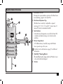
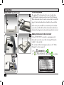
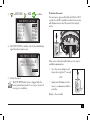
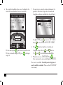
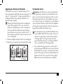
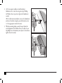
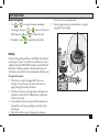
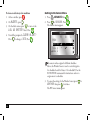
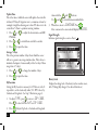
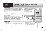
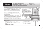
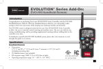
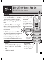
EVOLUTION® Series Add-On:
EVO-WS Weather Sensor
Introduction
Congratulations on purchasing Toro’s new EVOLUTION Series
Controller with the EVO-WS Weather Sensor Add-On. With the
Weather Sensor Add-On, you will quickly realize savings in
both time and money while keeping your garden healthy and
beautiful.
The EVO-WS Wireless Weather Sensor system is designed
exclusively for your Toro EVOLUTION Series Controller to
continuously monitor and adjust automatic watering to suit
current watering needs.
The Wireless Sensor system consists of a remote Weather
Sensor. The sensor detects current sunlight level, temperature and
rainfall, then transmits this information wirelessly to the
Smart Connect™ (offered seperately) device plugged into the
EVOLUTION Series Controller. The controller then adjusts the
running time to provide the optimum
amount of water required for the
next watering day.
To familiarize yourself with
EVO-WS Weather Sensor system,
please take a few moments to read
through this guide in its entirety.
LISTED
FCC-ID: OF7WS9
IC: 3575A-WS9
Specifications
• Dimensions:
2.75” (7 cm) W x 7” (17,8 cm) H (over 2” [5 cm] antenna) x 6.25” (15,9 cm) D (over 4” [10,2 cm] mounting
bracket)
• 9V Alkaline battery (included)
• RF reception range:
1000’ (305 m) LOS (line of sight)
• Operating temperature range:
14° – 140° F ( -10°– 60°C)
1
Table of Contents
Specifications1
Weather Sensor Overview3
Installation4
Smart Connect™4
The SD Card Explained
4
Adding the Sensor to the Controller
4
Adjusting the Rain Sensor Threshold
7
Weather Sensor7
Basic Operation9
Menu Navigation9
Battery Replacement9
Getting to the Sensors Menu
10
Weather Sensor Menu
11
Current Adjust 2
11
Temperature 11
Rain Status11
Freeze Off11
Dryout Days11
Water Adjust11
Update Time12
Average % Days
12
My Location12
Signal Strength12
Battery Level12
Review13
Resetting to Factory Defaults
13
Wireless Communication Problems
13
Toro Warranty and Support
14
Installation Notes15
Weather Sensor Overview
1
3
2
4
5
1. Rain Sensor Test Pin
Pressing the test pin simulates operation of the Rain Sensor
by transmitting a signal to the Smart Pod.
2. Rain Sensor Adjustment Cap
The Rain Sensor sensitivity is adjustable to suspend
watering at 1/8”, 1/4”,, 1/2” and 3/4” (3 mm, 6 mm, 12
mm and 19 mm) of accumulated rainfall.
3. Solar Collector
Solar radiation and temperature are used by the Smart Pod
to calculate and adjust watering to suit current weather
conditions.
4. Battery Compartment
A 9V Alkaline battery (installed) can provide Weather
Sensor operation up to five years.
See battery service information on page 9 for additional
information.
5. QuickClip™ Mounting Bracket
The QuickClip bracket design enables the Weather Sensor
to be easily installed and aligned.
6. Antenna
6
3
Installation
EVOLUTION® Smart Connect™
1
2
SD Card Explained
The supplied SD card contains forty years of weather data
for all latitudes, longitudes, and zip codes in North America.
When the weather sensor's location is entered in the controller
(page 6), historical weather data is loaded into the controller.
In the event your controller loses connectivity to the weather
sensor, the controller will use the the historical weather data to
determine the irrigation run time until connectivity is restored.
3
5
4
Adding the Sensor to the Controller
For the EVOLUTION® controller to communicate with
the weather sensor, the sensor (with its unique ID) must be
“added” to the controller.
(For assistance with menu navigation, please see the "Menu
Navigation" section on page 9.)
1. Press
ADVANCED then
.
2.
to ADD/REMOVE DEVICE.
→
→
ADVANCED
ZONE DETAILS
SCHEDULE STARTS
SCHEDULE DETAILS
SENSORS
ADD/REMOVE DEVICE
4
to confirm.
to WEATHER.
3.
to ADD.
to confirm.
→
ADD/REMOVE DEVICE
WEATHER
ADD
SOIL 1
ADD
SOIL 2
ADD
SOIL 3
ADD
AUX 2
ADD
To activate the sensor:
For new sensors, press and hold the Test Pin for 10-15
seconds. A red LED, viewable from the lower vent area,
will illuminate twice after 10 seconds (if not already
active).
4. The EVOLUTION® controller waits for the identification
signal from the weather sensor.
ADD/REMOVE DEVICE
PRESS TEST PIN OR
WAIT FOR SIGNAL
. .
CANCEL
5. Activate the sensor.
The EVO-WS Weather Sensor is shipped with the
battery circuit deactivated. It is necessary to activate the
sensor prior to installation.
!
If the sensor is already installed, there are two ways to
establish communication:
• Go to the sensor and press and
release the test pin for 15 seconds
- OR • Simply wait 30 minutes for the
sensor to communicate with the
controller.
Return to the controller.
5
6. The controller should detect the sensor. Confirm that the
device ID detected matches the sensor’s actual ID.
ADD/REMOVE DEVICE
WEATHER
DEVICE ID 05 43 31
STATUS
INACTIVE
CORRECT?
YES
SN: 054331
If it does match, press
and continue to add the sensor.
If it does not match, change to NO, press
, and repeat
steps 3-6.
7. The next step is to enter the location information. It is
possible to enter either by zip code or Latitude and
Longitude coordinates (available from Google Maps®).
MY LOCATION
ZIP CODE
ZIP CODE
92504
CONTINUE
TYPE
To adjust TYPE, press
to move to ZIP CODE.
Press
to select LONG/LATor ZIP CODE.
8. Press
. Adjust the Zip Code or Latitude and
Longitude values with the
and
buttons.
Use
and
to switch between number fields.
9. When done, move to CONTINUE. Press
.
After a moment, the screen should display SUCCESS.
The sensor is now added. To actually control irrigation, it
must be added to a schedule. (Please see the EVOLUTION®
user manual.)
6
Adjusting the Rain Sensor Threshold
The Weather Sensor is preset to suspend watering at 1/4” (6
mm) of accumulated rainfall. Three alternate settings of 1/8” (3
mm), 1/2” (12 mm) and 3/4” (19 mm) are provided. Prior to
installing the Weather Sensor, adjust the threshold to the
preferred setting as required.
Increasing the threshold setting results in extending the
length of timer required for the sensor to shut off or
postpone watering during rain, as well as extending the
dry-out period before scheduled watering will resume.
In areas where heavy fog or mist is common, the 1/8” (3
mm) setting may not provide accurate rain detection, and
is not recommended.
1. Turn the cap slightly, releasing it from the two retaining pins.
2. Adjust the cap to engage the pins at the preferred slot setting.
1/4” (6.4mm)
1/2” (13mm)
The Weather Sensor
! Important: The Weather Sensor must have full exposure
to sun, wind and rain, and must not be installed inside a rain
gutter, or in any location where immersion, runoff, or contact
with irrigation spray will occur. Avoid installation near a heat
source, such as a heater vent or chimney. Also avoid installation
near any large metal structure or high current-draw equipment
that may generate signal interference. Ensure the antenna wire
hangs unobstructed below the Weather Sensor.
The communication range of the Wireless Weather Sensor
system is 1000’ (305 m) LOS (line of sight). Some loss of
range can be expected due to interference from obstacles
in the signal path. Test the signal reception from the
proposed installation site prior to mounting the Weather
Sensor, as described in the following procedure.
1. Start a manual watering operation for a zone that can be
seen from the proposed Weather Sensor location. Press and
hold the Rain Sensor test pin to send a signal to the Smart
Connect. If the signal is received, watering should shut off
within a short time. If not, repeat the test from a slightly
different location, until communication is established.
7
2. (A) For rain gutter installation: back the bracket
thumbscrew out to clear the rain gutter edge. Holding
the Weather Sensor in position, tighten the thumbscrew
securely.
(B) For solid structure installation: remove the thumbscrew
and secure the bracket using the provided stainless screws
(or other appropriate stainless fasteners).
3. With the mounting bracket securely fastened, check the
vertical alignment of the Weather Sensor. To adjust, loosen
the phillips screw at the bracket joint, adjust to vertical, then
tighten the screw securely.
8
A
B
Basic Operation
Menu Navigation
• Use
or
to navigate the menu commands.
• To change a value, press
field, then press
and
• Remember to press
or
to move to the desired
to adjust the value.
dome above the mounting bracket.
5. Turn the upper housing counterclockwise to securely
engage the lower housing.
to input the desired value.
Battery
Under normal operating conditions, the Weather Sensor battery
can last up to five years. A weak battery condition in the sensor
is indicated on the EVOLUTION controller: the red LED will
flash and you will be prompted to check the Alerts screen. A
weak battery can result in loss of communication with the sensor.
9V
To replace the battery:
1. The battery is stored in the upper half of the sensor
housing. To access the battery, release and remove the
upper housing by twisting it clockwise.
2. Disconnect the battery wire clip. Remove and replace the
used battery with a fresh 9V Alkaline battery. Reconnect
the battery wire clip.
3. To reassemble the sensor housing, thread the antenna wire
through the lower housing, exiting the center hole in the
bottom grid.
4. Mate the two halves squarely, aligning the translucent
9
To clear a weak battery alert condition
1. At the controller, press
.
2. On ALERTS, press
.
3. On the Alerts screen, press
to move to the
LOW WS BATTERY alert. Press
.
4. You will be prompted to CLEAR ALERT?
Press
to change to YES. Press
.
Getting to the Sensors Menu
1. Press
ADVANCED then
2. Press
to SENSORS. Press
The Sensors screen appears.
.
C
-
→
SENSORS
A
B
ALERTS
CLEAR ALL
RAIN
LOW WS BATTERY
WEATHER
-
SOIL 1
-
SOIL 2
.
The sensors can be assigned to different schedules.
Above, the Weather Sensor is used to control irrigation
for schedules A and Soil Sensor 1 for schedule B. See the
EVOLUTION user manual for instructions on how to
assign sensors to schedules.
3. To access the settings for the Weather Sensor, press
WEATHER then press
four times.
The WS Sensor menu appears.
10
to
Weather Sensor Menu
→
SENSORS
CURRENT ADJUST
TEMPERATURE RAIN STATUS FREEZE
OFF AT
DRYOUT DAYS
Rain Status
Displays the state of the rain sensor: “Dry” or “Wet”.
--81°F
DRY
39°F
02
Current Adjust
The percentage that the weather sensor is going to adjust the
irrigation runtime. Possible values range between OFF and
+150, though realistically, values will display between ±35%.
For example, if the evapotranspiration (ET) historical data
calls for a hot season, but the week has in fact been cloudy, the
“Current Adjust” might show "-20%" to reflect the decreased
runtime. It can also display “OFF”.
Temperature
Displays the current temperature at the sensor location.
Temperature unit (Celcius or Farenheit) can be changed in the
controller preferences settings (see the EVOLUTION® user
manual).
Freeze Off
The temperature at which irrigation will be turned off due to
cold temperatures. Selections range from 35°-45°F in 2 degree
increments.
1. Press
or
to raise or lower the temperature value.
2. Press
to input the value.
Dryout Days
After a rain, it is not always necessary to resume irrigation right
away. Setting a Dryout Days period, from zero to 14 days,
delays the automatic resumption of irrigation.
1. Press
or
to increase or decrease the number of
days to “dryout”.
2. Press
to input the value.
Water Adjust
Water Adjust allows the runtime of all stations in all schedules
to be adjusted by a maximum of ±35%. So, for example, if
the programmed runtime for station 1 is 10 minutes, setting
a Water Adjust of +35% would adjust that run time to 13
minutes, 30 seconds. This is useful for seasonal changes.
1. Press
or
to increase or decrease the percentage
of irrigation runtime.
2. Press
to input the value.
11
Update Time
This is the time at which the sensor will update the controller
with new ET data. If irrigation were to commence at 6am, for
example, it might be advantageous to have ET data sent to the
controller at 5:45am to optimize watering runtimes.
1. Press
or
to adjust the hour, minute, and AM/
PM fields.
2. Press
3. Press
or
to switch from one field to another.
to input the value.
2. Press
to input the value.
My Location
Setting the My Location is necessary for ET data to work. It
is possible to set the location by either U.S. ZIP Code or by
Latitude and Longitude. (See Step 7 illustration, page 6.)
1. To adjust TYPE, press
to move to ZIP CODE.
Press
to select LONG/LATor ZIP CODE.
2. Press
12
. Adjust Zip Code or Latitude and Longitude
3. When done, move to CONTINUE. Press
.
After a moment, the screen should display SUCCESS.
Signal Strength
Indicates signal strength as a series of bars ( ).
WEATHER SENSOR
AVERAGE % DAYS
ID
MY LOCATION
SIGNAL STRENGTH
BATTERY LEVEL
4.5V
→
Average % Days
This is the previous number of days from which the sensor
will use to generate an average runtime value. This is done to
minimize the impact of unseasonably cold or hot days. Values
range from 1-7 (days).
1. Press
or
to change the number of days.
values with the
and
buttons.
Use
and
to switch between number fields.
Battery Level
Displays the charge level of the battery in the weather sensor,
with 9V being fully charged. (See above illustration.)
Review Screen
The Review screen allows operators to review settings
for the various sensors added to the controller.
1. Press the Review button.
2. Press
to the WEATHER SENSOR. Press
3. Use
to scroll through the various sensor settings.
→
REVIEW
WEATHER SENSOR
ADJUST --RAIN STATUS
WET
SENSOR TEMP
81°F
SIGNAL STRENGTH
Resetting to Factory Defaults clears ALL SENSOR
SETTINGS and ALL ADDED IDs.
1. Go to the Sensors screen (page 10) and scroll down to
SMART CONNECT. Press
.
!
SENSORS
A
B
SOIL 1
-
SOIL 2
SOIL 3
SMART CONNECT
C
-
→
REVIEW
SCHEDULE A
SCHEDULE B
AUX 2
RAIN SENSOR
WEATHER SENSOR
.
Resetting to Factory Defaults
2. Change the value to YES and press
.
Wireless Communication Problems
The effective range of the EVO-WS Weather Sensor is 1,000 feet. That
range can be impacted by walls and/or electrical appliances that cause
radio interference.
If you experience wireless communication problems, try the following:
• Install the sensor as close to the controller location as possible. If
the signal strength is not good in one location, try another location
nearby. Sometimes moving the sensor only a few feet can greatly
improve signal strength.
13
Toro Support
Toro Commitment to Quality
Toro is committed to developing and producing the highest quality, best performing, most dependable products on the market. Because your satisfaction
is our first priority, we have provided the Toro Helpline to assist you with any
questions or problems that may arise. If for some reason you are not satisfied
with your purchase or have questions, please contact us toll free at
1-877-345-8676.
Warranty
The Toro Company and its affiliate, Toro Warranty Company, pursuant to
an agreement between them, jointly warrants, to the owner, against defects
in material and workmanship for a period of five years from the date of
purchase. Neither The Toro Company nor Toro Warranty Company is liable
for failure of products not manufactured by them, even though such products
may be sold or used in conjunction with Toro products.During such warranty
period, we will repair or replace, at our option, any part found to be defective. Return the defective part to the place of purchase. Our liability is limited
solely to the replacement or repair of defective parts. There are no other
express warranties. This warranty does not apply where equipment is used, or
installation is performed, in any manner contrary to Toro’s specifications and
instructions, nor where equipment is altered or modified. Neither The Toro
Company nor Toro Warranty Company is liable for indirect, incidental or
consequential damages in connection with the use of equipment, including
but not limited to: vegetation loss, the cost of substitute equipment or services required during periods of malfunction or resulting non-use, property
damage or personal injury resulting from installer’s negligence.
Some states do not allow the exclusion or limitation of incidental or consequential damages, so the above limitation or exclusion may not apply to you.
All implied warranties, including those of merchantability and fitness for use,
14
are limited to the duration of this express warranty. Some states do not allow
limitations of how long an implied warranty lasts, so the above limitation
may not apply to you. This warranty gives you specific legal rights and you
may have other rights which vary from state to state.
FCC Part 15 Rules
This equipment has been tested and found to comply with the limits for a
Class B digital device, pursuant to Part 15 of the FCC Rules. These limits
are designed to provide reasonable protection against harmful interference
in a residential installation. This equipment generates, uses and can radiate
radio frequency energy and, if not installed and used in accordance with
the instructions, may cause harmful interference to radio communications.
However, there is no guarantee that interference will not occur in a particular
installation. If this equipment generates interference to radio or television
reception, which can be determined by turning the equipment on and off,
the user is encouraged to try to correct the interference by one or more of the
following measures:
1. Reorient or relocate the receiving antenna.
2. Increase the separation between the equipment and receiver.
3. Connect the equipment into an outlet on a circuit different from that to
which the receiver is connected.
4. Consult the dealer or an experienced radio/TV technician for help.
The user may find the following booklet prepared by the Federal Communications Commission helpful: “How To Identify and Resolve Radio-TV
Interference Problems”. This booklet is available from the U.S. Government
Printing Office, Washington, DC 20402. Stock No. 004-000-00345-4.
Installation Notes
15
The Toro Company
5825 Jasmine Street
Riverside, CA 92504
16
©2014 The Toro Company, Irrigation Division • www.toro.com • 1-877-345-8676
Form Number 373-0806 Rev. A