Transcript
Little Giant
P. O. Box 12010
Oklahoma City, OK 73157-2010
405.947.2511 • Fax: 405.947.8720
www.LittleGiant.com
[email protected]
LITTLE GIANT
SEWAGE ACCESSORIES
& INSTRUCTIONS FOR
TYPICAL INSTALLATION
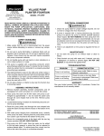
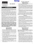
Figure 1.
Pre-Packaged
ASSEMBLY INSTRUCTIONS FOR
9S-SMPX-LG
10S-SMPX-LG
(BOLT-ON VENT/DISCHARGE FLANGES)
PRE-PACKAGED UNIT (FIGURE 1):
Verify all parts with basin and cover assemblies are received intact. The flanges provided will allow the following discharge/vent combinations to be
used: 3” discharge/2” vent, or a 2” discharge/2” vent, depending on cover
configuration. Please note that basin should be backfilled with cover
secured on basin to ensure that cover holes will align properly.
1. Remove bolts and washers in cover and set aside.
2. Remove gasket material from hardware kit and place material around
circumference of basin inside of bolt circle.
3. Place the pump on a flat surface and install the discharge pipe in
the discharge of the pump.
4. Install float switch 4” above discharge of pump with a 3-1/2” tether
length. Float switch should be installed in a manner that will not
allow it to contact the pump or side of basin during operation. Refer
to float switch instruction manual for alternative settings. Place the
pump in the basin in the torque stops.
5. To install the cover, pull the pump and float cords through the smallest hole in the cover. Place the cover on the basin, making sure
the discharge pipe is through the proper hole in the cover (holes are
labeled on bottom of cover). Secure the lid to the basin, using the
bolts and washers provided. Place the larger square-cut O-ring on
discharge pipe with beveled edge down. Install flange and tighten
bolts. Place the remaining O-ring in the bottom of the vent flange
with beveled edge down. Install flange and tighten bolts.
6. Pull the slack out of the cords and install them through the grommet
1–2 inches above the cover. Press the grommet in the hole in the cover.
7. Install a 2” vent pipe by threading it on the vent flange. Make sure
the flange bolts are tight.
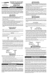
PRE-ASSEMBLED UNIT (FIGURE 2):
The pre-assembled unit is furnished fully assembled and ready for
installation. Remove check valve or ball/check valve from discharge
pipe and re-install as shown on typical installation (Figure 3). CAUTION:
For best performance of check valves when handling solids, install in
a horizontal position or at an angle of not more than 45°. Do not install
check valve in a vertical position, as solids may settle in valve and
prevent opening on start-up. Remove the cord from the vent hole and
install the vent pipe (see Figure 3 to complete typical installation).
To test the unit, plug the unit in and run water into the basin until the unit
switches on. If the unit does not operate, refer to the troubleshooting
information in the instructions for the pump.
ITEM
1
2
2
*
4
4
5
6
7
7
8
8
8
REPLACEMENT PARTS LIST
DESCRIPTION
QTY.
BASIN, 20” x 30”
1
COVER ASSEMBLY, 2” DISCHARGE
1
COVER ASSEMBLY, 3” DISCHARGE
1
COVER ASSEMBLY HARDWARE KIT
1
FLANGE, 2” DISCHARGE PIPE
1
FLANGE, 3” DISCHARGE PIPE
1
FLANGE, 2” VENT PIPE
1
GROMMET, 2-HOLE
1
PIPE, DISCHARGE 2”
1
PIPE, DISCHARGE 3”
1
CHECK VALVE, 2”
1
CHECK VALVE, 3” (only on 509112 & 509113)
1
CHECK VALVE/BALL VALVE, 2” (only on 509106,
940026
1
509107 & 14940684)
P/N
113095
113180
113181
113171
113214
113216
113215
N/A
113423
113424
940022
940023
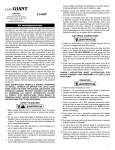
Figure 2.
Pre-Assembled
Figure 3.
Typical Installation
©Copyright 2006 Little Giant
Form 998264 — 03/2006
Little Giant Print Services