1
LITTLE GIANT QUALITY
Little Giant
P. O. Box 12010
Oklahoma City, OK 73157-2010
405.947.2511 • Fax: 405.947.8720
www.LittleGiant.com
[email protected]
10-CIA
10-CIM
12-CBA
12-CBM
INTRODUCTION
Little Giant pumps are carefully packaged, inspected and tested
to insure safe operation and delivery. When you receive your
pump, examine it carefully to determine that there are no broken
or damaged parts that may have occurred during shipment. If
damage has occurred, make notation and notify the firm you purchased the pump from. They will assist you in replacement or
repair, if required.
SAFETY GUIDELINES
WARNING: Risk of electric shock. This pump is supplied with a
grounding conductor and grounding-type attachment plug. To
reduce the risk of electric shock, be certain that it is connected
only to a properly grounded, grounding-type receptacle.
Every pump has been factory tested for capacity, control operation and electrical continuity to assure maximum performance and
safety. Little Giant automatic sump pumps have a high volume
pumping capacity with a pressure activated switch. The switch
engages in 8-1/2"–12" of water. Other pumps are available in
epoxy coated cast iron housings or corrosion resistant cast
bronze. Maximum operating temperature is 120°F.
The motor section of your pump is permanently lubricated and
sealed - do not attempt to open this section. Special equipment
and knowledge is required for proper servicing of this part of your
pump and may only be accomplished by an Authorized Service
Center or the factory. Your warranty will be void if the motor section is opened by unauthorized persons.
ELECTRICAL CONNECTIONS
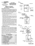
Your sump pump is supplied with a 3-prong electrical plug (see
Figure 1). The third prong is to ground the pump to prevent possible electric shock hazard. Do not remove the third prong from
the plug. A separate branch electrical circuit is recommended. Do
not use an extension cord.
Figure 1.
1. Read all instructions and safety guidelines thoroughly. Failure
to follow the guidelines and the instructions could result in
serious injury and/or property damage.
2. Check local electrical and building codes before installation.
The installation must be in accordance with their regulations.
3. During normal operation the sump pump is immersed in
water. Also, during rain storms, water may be present in the
surrounding area of the pump. Caution must be used to prevent bodily injury when working near the pump:
a.The plug must be removed from the receptacle prior to
touching, servicing or repairing the pump.
b.To minimize possible fatal electrical shock hazard, extreme
care should be used when changing fuses. Do not stand in
water while changing fuses or insert your finger into fuse
socket.
4. Do not run the pump in a dry sump. If the pump is run in a
dry sump, the surface temperature of the pump will rise to a
high level. This high level could cause skin burns if the pump
is touched and will cause serious damage to your pump.
5. Do not oil the motor. The pump housing is sealed. A high
grade dielectric oil devoid of water has been put into the motor
housing at the factory. Use of other oil could cause serious
electric shock and/or permanent damage to the pump.
6. This pump’s motor housing is filled with a dielectric lubricant
at the factory for optimum motor heat transfer and lifetime
lubrication of the bearings. Use of any other lubricant could
cause damage and void the warranty. This lubricant is nontoxic; however, if it escapes the motor housing, it should be
removed from the surface quickly by placing newspapers or
other absorbent material on the water surface to soak it up, so
aquatic life is undisturbed.
7. In any installation where property damage and/or personal
injury might result from an inoperative or leaking pump due to
power outages, discharge line blockage, or any other reason,
a backup system(s) and/or alarm should be used.
INSTALLATION
1. Clean any debris from sump pit and set pump in center of pit.
A solid bottom will prevent clogging of the pump from sand
and dirt.
2. Connect discharge piping and run it to the nearest sewer or
surface outlet. Use pipe joint compound at all connections.
Sump pumps can be piped to discharge into the house drainage system, to a dry well, splash block or to a storm drain,
depending on local plumbing codes. The discharge pipe
should be as short as possible and contain as few elbows as
possible. The discharge pipe should be the same diameter
as the discharge size to reduce pipe friction losses. Smaller
pipe will restrict capacity and reduce pump performance. The
sump pump comes with 1-1/2” female pipe thread discharge.
3. Always install a union in the discharge line, just above the
sump pit, to allow for easy removal of the pump for cleaning
or repair.
4. In situations where the piping is long, the vertical discharge is
above 7 or 8 feet, or a small pit has been provided, use of a
check valve is recommended to prevent backflow of water into
the sump. When a check valve is used, drill a relief hole (1/8”
or 3/16” diameter) in the discharge pipe. This hole should be
located below the floor line between the pump discharge and
the check valve. Unless such a relief hole is provided, the
pump could “air lock” and will not pump water even though it
will run.
5. Tape power cord to discharge line with electrician’s tape. This
will protect the cord from damage and will prevent the pump’s
being pulled from the sump by its power cord.
6. TEST THE PUMP AFTER ALL CONNECTIONS HAVE BEEN
MADE. Run water into sump. Do not attempt to operated the
pump without water; this will damage the seals and bearings
and could result in permanent damage to the pump. Fill sump
to normal “on” level and allow pump to remove water to the
normal “off” level (see Figure 2).
Figure 2.
7. Place cover over sump. This cover will prevent solid debris
from filling the pit, prevent odors, and guard against accidental
injury.
WARNING: Always disconnect the electical power before touching
the pump or discharge when water is present in the sump. Failure
to do so can result in hazardous electrical shock.
TROUBLESHOOTING INFORMATION • INFORMATION SUR LA RELÈVE DES DÉRANGEMENTS
• INFORMACION DE INVESTIGACION DE AVERIAS
PROBLEM • FONCTIONNEMENT DÉFECTEUX
• PROBLEMA
Pump will not shut off.
PROBABLE CAUSES • CAUSES PROBABLES
• CAUSAS PROBABLES
Diaphragm switch.
Replace switch.
Weak of hardened rubber diaphragm.
Replace rubber diaphragm.
Plugged vent tube.
Clear vent tube of any obstruction.
Dirt or sediment lodged between retainer ring and
NOTE: Before troubleshooting automatic rubber diaphragm causing contacts to remain closed.
control, check to see that pump operates
on manual control. To do this, create slight
vacuum on breather tube (near plug), Pump is air locked.
then close off tube with thumb, plug into
wall outlet. If pump works, proceed to
check switch; if not, fault is in pump or Liquid inflow matches pump capacity.
power supply.
Defective switch.
Pump runs, but does not discharge
liquid.
Pump does not deliver rated capacity.
Pump cycles continually.
CORRECTIVE ACTIONS • SOLUTIONS • SOLUCION
Clean area around rubber diaphragm.
Shut power off for approximately 1 minute, then restart.
Repeat several times to clear air from pump. If system includes
a check valve, a 3/16" hole should be drilled in discharge
pipe approximately 2" above discharge connections.
Larger pump required.
Disconnect switch, check w/ohmmeter. Open-infinitive
resistance, closed zero.
Loose connection in level control wiring.
Check control wiring.
Check valve installed backwards.
Check flow indicating arrow on check valve body to ensure
it is installed properly.
Check valve stuck or plugged.
Remove check valve and inspect for proper operation.
Lift too high for pump.
Check rating table.
Inlet to impeller plugged.
Pull pump and clean.
Pump is air locked.
(See corrective action above).
Lift too high for pump.
Check rated pump performance.
Low voltage, speed to slow.
Check for proper supply voltage to make certain it corresponds to nameplate voltage.
Impeller or discharge pipe is clogged.
Pull pump and clean. Check pipe for scale or corrosion.
Impeller wear due to abrasives.
Replace worn impeller.
No check valve in long discharge pipe allowing
liquid to drain back into sump.
Install a check valve in discharge line.
Check valve leaking.
Inspect check valve for correct operation.
Sump pit too small for inflow.
Install a larger sump pit.
Figure 3.
12-CBA
512155
12-CBM
512055
10-CIA
510156
10-CIA
510155
10-CIM
510055
REPLACEMENT PARTS LIST
ITEM
NO.
PART
NO.
1
111704
Housing, Manual Switch Assembly, 10' (115V)
1
111705
Housing, Automatic Switch Assembly, 10'
1
111706
Wiring Harness Assembly, with Tube, 25'
2
902307
Screw, Tap #6-32 x 1/4"
3
3
3
3
3
3
921028
Washer, Lock #6
•
•
•
•
•
909025
Screw/Washer #10-24 x 1-3/4" (SST)
6
4
4
909033
Screw/Washer #10-24 x 1-3/4" (brass)
5
112120
Clamp, Strain Relief
•
•
•
6
902409
Screw, Tap, 8-18 x 3/4"
2
2
2
2
2
8
951964
Lead Wire, Red
•
•
•
•
•
4
DESCRIPTION
•
•
•
•
•
6
4
•
•
9
901306
Screw, #6-32 x 3/16"
3
3
3
3
3
10
951963
Lead Wire, Black
•
•
•
•
•
11
950930
Relay
•
•
•
•
•
12
928019
Seal Ring
•
•
•
•
•
13
112121
Bracket, Switch Relay
•
•
•
14
112119
Pad, Insulating
•
•
•
15
950323
Switch, Miniature
•
•
•
16
951976
Lead Wire, Black
•
•
•
17
909034
Screw/Washer, #4-40 x 9/16"
2
2
2
18
108125
Diaphragm
•
•
•
19
108055
Cover, Switch Housing
•
•
•
909022
Screw/Washer #10-24 x 5/8"
2
2
901521/
921002
Screw/Washer #10-24 x 5/8" (bronze)
901523/
921023
Screw/Washer #10-24 x 2-1/8"
901528/
921002
Screw/Washer #10-24 x 2-1/8" (bronze)
110033
Base
112033
Base
909021
Screw/Washer #10-24 x 1/2" (SST)
909009
Screw/Washer #10-24 x 1/2" (brass)
110082
Screen, Intake
112082
Screen, Intake (brass)
110092
Plate, Screen
112092
Plate, Screen (bronze)
909023
Screw/Washer #10-24 x 3/4"
909019
Screw/Washer #10-24 x 3/4" (brass)
20
21
22
23
24
25
26
2
2
2
•
•
•
3
3
3
•
•
•
•
•
•
3
3
3
2
•
•
3
3
•
•
•
•
3
3
ONE YEAR LIMITED WARRANTY
For one year from date of purchase, Little Giant Pump Company
will repair this pump if defective in material or workmanship.
Warranty service is available through a nationwide network of
warranty service stations or by returning the pump prepaid to the
factory. For further details, please consult the warranty statement
on carton. This warranty gives you specific legal rights, and you
may also have others rights which may vary from state. to state.
For Parts or Repair, please contact . . . . . . . . . . . . . . . . . . . . . . . . . . . . . . . . . . . 1.888.572.9933
For Technical Assistance, please contact . . . . . . . . . . . . . . . . . . . . . . . . . . . . . . 1.888.956.0000
www.LittleGiant.com
[email protected]
©Copyright 2006 Little Giant
Form 993173 — 09/2006
Little Giant Print Services