1
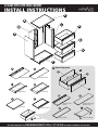
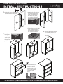
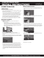
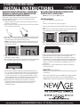
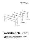
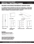
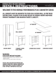
24 Gage Steel RTA tool Cabinet
Install Instructions
READ THIS FIRST BEFORE UNPACKING CABINET
All cabinets must be mounted to studs on a secure wall, as per these
instructions. Failure to do so may result in serious injury and voids
product warranty and manufacturer’s liability.
WARNING:
Do not overload cabinets!
Cabinets are designed
to carry the following
maximum weight
capacities:
Cabinet
Shelf Weight
Overall Weight
Capacity (lbs)
Capacity
Locker
50
200
Wall
40
80
Base
50
150
Tool
30
150
Parts and Hardware Supplied
with Base Cabinet:
Qty
Item
1
Locking Rod
47
M5 Frame Screw
47
M5 Frame Nut
4
Adjustable Leg
16
M8 Leg Screws
16
M8 Leg Screw Nut
18
M8 Large Washer
16
Lock Washers
2
2.5” Wall Screw
4
5/8” Wood Screw
Image
Do not leave children unattended near cabinets.
When fully loaded, cabinets are heavy and there is a
risk of cabinets or items tipping if improperly opened.
Cabinet should be mounted to wall to avoid injury
WARNING:
Excessive Weight Hazard
• Use two or more people to move, assemble or install cabinet or
locker.
• Failure to do so can result in back or other injury.
Unpacking OF THE Cabinet:
•
•
•
•
•
Begin by placing the cabinet on a sound level surface.
Remove all cardboard and foam packaging material.
Remove clear plastic bag.
Dispose / recycle all packaging materials.
Remove and verify all the contents in the box. See “Parts and
Hardware Supplied List”
need more information? try, www.NewAgeProducts.com or 1 877 306 8930 for answers to commonly asked questions.
24 Gage Steel RTA Tool Cabinet
Install Instructions
E
A
C
B
G
D
G
G
F
A
G
B
Z
Y
X
Left Back Panel
Right Back Panel
C
Drawer Components
D
W
Right Panel
Left Panel
W
E
X
F
Drawer Front
Panel
Top Panel
Bottom Panel
G x3 Drawer
Z
Drawer Back
Support Panel for
Drawer Front
Y
Drawer Bottom
need more information? try, www.NewAgeProducts.com or 1 877 306 8930 for answers to commonly asked questions.
24 Gage Steel RTA Tool Cabinet
Install Instructions
1. Use the M5 screw and M5 nut to
2. Assemble the left and right
assemble the two back panels.
side panel with the same
screw and nut. D Goes on
the outside of A, and C
goes on the outside of B.
B
C
D
A
4. Flip the cabinet over. Use M8
screw, washer and M8 nut
to assemble the adjustable
legs on the bottom panel.
3. Panel E sits on
the outside of
A and B, and
on the inside
of C and D. Do
the same for
panel F.
5. Turn the cabinet back upwards
and assemble drawers. See
drawn assembly instructions on
next page.
E
E
F
F
E
F
G
6. To install drawers, line
up runners on the
side of the drawer
with the track on the
inside of the cabinet
and guide it into
place.
need more information? try, www.NewAgeProducts.com or 1 877 306 8930 for answers to commonly asked questions.
24 Gage Steel RTA Tool Cabinet
Install Instructions
Y
Z
W
X
Z
W
Drawer assembly:
X
Y
**Below is what it will look like when Z has fit into the notches
along the side and bottom of Y.
1)Bend the two sides of DRAWER BOTTOM (Y) upwards to create
the side walls.
Notch
a
Notch
3. Insert the edge without the ridge of DRAWER PANEL (W) at
the other side of DRAWER BOTTOM (Y). You may use a mallet
to apply force. Note: Drawer bottom must rest on the inside of
DRAWER PANEL (W).
The Steel Metal Runners should be on the outside of the drawer.
2)Insert the edge of (Z) with 3 notches into the back of DRAWER
BOTTOM (Y) using a mallet to wedge into place. Make sure all the
notches at tops and sides of (Y) are snapped into notches on (Z).
4. Insert the SUPPORT PANEL (X) at the back of the DRAWER PANEL
(W), be sure to insert this with the ridges edge upwards. Bang
into place with a mallet. Once it passes the notches, it’s locked in.
need more information? try, www.NewAgeProducts.com or 1 877 306 8930 for answers to commonly asked questions.
24 Gage Steel RTA Base Cabinet
Install Instructions
Assembly Instructions:
Cabinet Leveling
(for all cabinets except for wall cabinet)
1.Place a small magnetic level onto the top of the cabinet to verify
the levelness of the cabinet.
2.If the floor slopes and the cabinet is not level, lift the adjustable
sleeve on the leg and adjust the cabinets height-adjustable
leveling leg by turning the nut on top of the cabinet’s foot, up or
down to bring the cabinet to a level position. This may require
two people, one person to verify / bring cabinet level and one
person to adjust the legs up and down simultaneously.
3.The cabinet must be adjusted front to back and side to side.
4.Do not put items in the cabinet until the leveling process is complete.
Enabling Locking Mechanism
1.Locate black vertical locking column attached to back-inside of
cabinet; this slides up and down. Push upwards to expose small
hole.
2.Locate Locking Rod, and insert the tip of the bent end into hole
in locking column at back of cabinet.
Mounting of the Worktop:
(optional, for base cabinets)
NOTE: Base Cabinet Drawers must be removed prior to
mounting Worktop.
• Pull each drawer out to full extension, simultaneously
depress the left lock up and right lock down in each slider
while pulling out the drawer. The drawer will slide out of the
tracks ready to remove. See the diagram to note where the
locks are on the drawer slides.
1.Place the Worktop on top of both the base cabinet .
2.Align the Worktop so that it is flush with the side of the base
cabinet.
3.Using the supplied Worktop hardware fasten screws through the
cabinet top into the Worktop. A cordless power drill is required to
drive the screws into the Worktop.
3.Locate the locking device at the top-inside of tool cabinet, and
locate the thin slit between the locking device. Remove the pin
attached to the cabinet lock, and set aside. Do not discard. Using
the other end of the Lock Rod with a hole through it, align this
with the lock hole.
4.Once holes are aligned, insert the pin through both to lock into
place, between lock slit.
Pin
5. Test the lock.
4. Put drawers back into base cabinet by aligning them with the
ball-bearing slides drawer tracks. The drawer should slide back
into place. Push the drawer fully into the cabinet, then pull it out
to full extension. If the drawer does not stop at full extension,
or feels loose, the drawer has not been put back into the drawer
slides properly. Ensure both drawer slides attached to the drawer
are running along the drawer slides attached to the frame of the
cabinet.
Locking device is now ready.
need more information? try, www.NewAgeProducts.com or 1 877 306 8930 for answers to commonly asked questions.
24 Gage Steel RTA Tool Cabinet
Install Instructions
Mounting Cabinets into Drywall / Studded Wall:
Warning: All cabinets must be mounted to studs
before loading the cabinets with items
Each locker or base cabinet must be mounted to the wall with at least
two of the provided mounting screws. Each wall cabinet must be
mounted with four screws.
1.Using a stud finder locate the studs in the wall where the wall
cabinet is to be placed.
2.Once studs are located, using a pencil and a level mark a vertical
line to indicate stud location.
3.Place the cabinet into position tight against the supporting wall.
4.Open the doors and locate the perforated mounting strip on the
top and bottom of the backside of the cabinet.
Note: the cabinet has a perforated strip of holes at the top and
bottom of the cabinet, the locker only has a perforated strip at
the top of the cabinet.
5.Align the previously marked stud lines with a perforated hole by
shifting the cabinet slightly.
6.Place a small magnetic level on top of the wall cabinet and adjust
the orientation of the cabinet to bring it to a level position.
7.Once leveled, using the supplied mounting hardware fasten a
2.5” x ¼” cabinet mounting lag bolt with a large washer through
the cabinet and into the stud. This can be done by hand with
a 7/16th socket wrench or a cordless power drill with a 7/16th
socket attachment. Do not over tighten bolts! Once the fender is
sitting tightly flush with the backside of the cabinet stop.
8.Repeat Step 6 three additional times with the remaining
mounting hardware to install the wall cabinet. You will only
repeat this one more time for the locker, as it only has 2
mounting lag bolts.
Wall and Locker Cabinet Wall Mounting into
Concrete Block / Masonry Wall:
NOTE: Masonry Hardware NOT Included
Required Hardware:
• 2 ¼” x ¼” Tapcon Concrete Anchor (4)
0r
•#10 x 2” Screw with 3/16” masonry plug (4)
1.Place the wall cabinet into position tight against the supporting
wall.
2.Open the doors and locate the perforated mounting strip on the
top and bottom of the backside of the cabinet.
3.Place a small magnetic level on top of the wall cabinet and adjust
the orientation of the cabinet to bring it to a level position.
4.Using a hammer drill, drill 4 pilot holes through the perforated
strip in the backside of the cabinet and through the wall.
5.Using either the 2 ¼” x ¼” Tapcon Concrete Anchor or #10 x 2”
Screw with 3/16” masonry plug method and the supplied fender
washers fasten the cabinet directly to the wall. This application
requires a cordless power dill with a #2 Philips bit for ease of
installation.
6.Repeat Step 3 - 4 three additional times with the remaining
mounting hardware.
Thank you for your purchase!
Please give us a call, or visit us online if you have any other questions
or comments.
Give us your feedback for a chance to WIN! Take our quick 2 minute
survey and enter for your chance to win something FREE from
NEWAGE! Visit the website for details at www.newageproducts.com
need more information? try, www.NewAgeProducts.com or 1 877 306 8930 for answers to commonly asked questions.
NewAge Products Inc. Steel Cabinetry Warranty
1 year limited manufacturer warranty
For one year from the date of purchase, when this product is installed, operated and maintained according to the
instructions attached to or furnished with the product, NewAge Products Inc. will replace the defective product or parts if
the part fails as a result of defective materials or workmanship.
NewAge Products Inc. will not pay for:
1. Service calls to correct the installation of any NewAge products or to instruct you how to use or install them.
2. Damage resulting from improper handling or shipping of products, or products damaged by accident, misuse,
abuse, fire, flood, improper installation, acts of God, neglect, corrosion, modification or mishandling.
3. Products damaged by improperly loading beyond the specified maximum weight capacity outlined in the
instructions provided with the product.
4. Repairs or replacement when your product is used in other than normal, single-family household use, such as
a commercial environment, or handled in any way inconsistent with the installation instructions included with
the product.
5. Cosmetic damage, including scratches, dings, dents or cracks in paint that do not affect the structural or functional
capability of the product.
6. Surfaces damaged due to chemical interaction resulting in corrosion of paint or metal.
7. Replacement parts for NewAge products outside Canada and the United States.
8. Replacement keys or locking mechanisms.
9. Loss of product contents due to left, fire, flood, accident or acts of God.
10. Shipping or freight fees to deliver replacement products or to return defective products.
11. Any labor costs during the limited warranty period.
DISCLAIMER OF IMPLIED WARRANTIES; LIMITATION OF REMEDIES
IMPLIED WARRANTIES, INCLUDING TO THE EXTENT APPLICABLE WARRANTIES OF MERCHANTABILITY OR FITNESS
FOR A PARTICULAR PURPOSE, ARE EXCLUDED TO THE EXTENT LEGALLY PERMISSIBLE. ANY IMPLIED WARRANTIES
THAT MAY BE IMPOSED BY LAW ARE LIMITED TO ONE YEAR, OR THE SHORTEST PERIOD ALLOWED BY LAW. SOME
STATES AND PROVINCES DO NOT ALLOW LIMITATIONS OR EXCLUSIONS ON HOW LONG AN IMPLIED WARRANTY OF
MERCHANTABILITY OR FITNESS LASTS, SO THE ABOVE LIMITATIONS OR EXCLUSIONS MAY NOT APPLY TO YOU. THIS
WARRANTY GIVES YOU SPECIFIC LEGAL RIGHTS, AND YOU MAY ALSO HAVE OTHER RIGHTS WHICH VARY FROM STATE
TO STATE OR PROVINCE TO PROVINCE
need more information? try, www.NewAgeProducts.com or 1 877 306 8930 for answers to commonly asked questions.