1
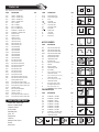
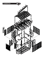
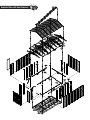
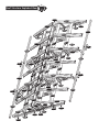
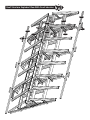
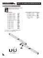
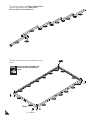
TM
A Product of
A L L
P U R P O S E
V I N Y L
USP
US POLYMERS INC
G A R A G E S
Vinyl Garage
Patent #416.091
OWNER’S MANUAL /
Instructions for Assembly
Size 10 Ft x 15 Ft (Approx.) with “Extension Kits”
Ver: 2.0
Customer
Service Hotline
(800) 483-4674
www.uspolymersinc.com
Your Total Solution To maintenance Free Garages.
Requires two people and takes about 4-5 hours for Installation.
PART 1
ASSEMBLING SHED WITH EXTENSION KIT
• All Weather Durable PVC
• Won’t Dent, Rust, Rot or Mildew
• Tall Walk In Shed
• Never Needs Painting
• 89” Wide Double Doors
• Easy Assembly
• High Wind Tested
• Snow Load Tested 20lbs/sq. foot
• Pad Lock Ready (Lock not included)
PART 2
ADDING EXTENSION KIT TO EXISTING SHED
Note: For shed with extension use this manual only.
Available Kits
Call us for any missing or damaged parts.
Do not return to the store.
• Window Kits Available
Building Dimensions (One Extension) :
Approximate
Size
Feet
10 x 2 1/2
Storage Area
Exterior Dimension
( Roof Edge to Roof Edge )
Interior Dimension
( Wall to Wall )
Sq. Ft.
Cu. Ft.
Width
( inch )
( inch )
Depth
Height
Width
Depth
Height
26 3/4
160 3/8
125 1/2
31
85 1/2
123 3/8
31
72
( inch )
( inch )
( inch )
( inch )
Duramax Garages
Limited Ten Year Warranty
U.S. Polymer Inc. will send a replacement part free of charge, in the event of material defects and or
workmanship for a period of ten years from the date of purchase.
This warranty is extended only to the original purchaser. A purchase receipt or other proof of date of
original purchase will be required before warranty service is rendered. In no event shall we pay the
cost of flooring, labor, installation or any other costs related thereto.
This warranty only covers failures due to defects in material or workmanship which occurs during normal
use and does not extend to color change arising due to normal weathering or to damage resulting from
misuse or neglect, commercial use, failure to follow assembly instructions and the owner’s manual
(including proper anchoring of the shed), painting, forces of nature and other causes which is beyond
our control.
Claims under this warranty must be made within the warranty period by calling 1-800-483-4674 or mail
in a dated sales slip and clear photograph of the part to:
U.S. Polymers, Inc.
1057 S. Vail Ave Montebello.
CA 90640
We reserve the right to discontinue or change components. If a component has been discontinued
or is not available,
U.S. Polymers, Inc. reserves the right to substitute a component of equal quality as may be compatible.
Limits and Exclusions
There are no express warranties except as listed above. The warrantor shall not be liable for incidental
or consequential damages resulting from the use of this product, or arising out of any breach of this
warranty. All express warranties are limited to the warranty period set forth above . Some states do
not allow the exclusion or limitation on how long an implied warranty lasts, so the above limitations may
not apply to you.
This warranty gives you specific legal rights and you may also have other rights which vary from state
to state or country to country.
Parts List
Note: Check all parts prior to installation.
CODE
DESCRIPTION
B1LH
B1RH
B1LA
B1RA
B21
B22
B3LA
B3RA
EXTL
EXTR
CMA
CMH
CCA
CDLA
CDLH
CDRA
CDRH
CB1A
CB1H
CB3A
CB3XA
CB4A
CB4H
CB6H
RS1H
RS2A
RS3LA
RS3LH
RS4XA
RS5A
RS6H
RS7H
RS13A
RS8H
RS9H
MJ
RS10A
RS11A
RS12A
RS14A
DSHH
RS19H
RS20H
RS15L
RS15R
FRONT ‘U’ CHANNEL LEFT
FRONT ‘U’ CHANNEL RIGHT
FRONT ‘U’ CHANNEL LEFT
FRONT ‘U’ CHANNEL RIGHT
SIDE ‘U’ CHANNEL
SIDE ‘U’ CHANNEL
BACK ‘U’ CHANNEL LEFT
BACK ‘U’ CHANNEL RIGHT
EXTENSION ‘U’ CHANNEL LEFT
EXTENSION ‘U’ CHANNEL RIGHT
MIDDLE COLUMN
MIDDLE COLUMN
CORNER COLUMN
LEFT DOOR COLUMN
LEFT DOOR COLUMN
RIGHT DOOR COLUMN
RIGHT DOOR COLUMN
CB1 CENTER BAND
CB1 CENTER BAND
CB3 CENTER BAND
CB3 CENTER BAND
CB4 CENTER BAND
CB4 CENTER BAND
CB6 CENTER BAND
RS1 ROOF STRUCTURE
RS2 ROOF STRUCTURE
RS3 ROOF STRUCTURE LONG
RS3 ROOF STRUCTURE LONG
RS4 ROOF STRUCTURE
RS5 ROOF SRTUCTURE
RS6 ROOF STRUCTURE
RS7 ROOF STRUCTURE
RS13 ROOF STRUCTURE
RS8 ROOF STRUCTURE SUPP. LONG
RS9 ROOF STRUCTURE SUPP. SHORT
MIDDLE JOINING SUPPORT
RS10 ROOF STRUCTURE SUPPORT
RS11 ROOF STRUCTURE SUPPORT SHORT
RS12 ROOF STRUCTURE SUPPORT LONG
SAGGING SUPPORT
DOOR STOPPER HORIZONTAL
VERTICAL SUPPORT - 1
VERTICAL SUPPORT - 2
RS15 ROOF STRUCTURE SUPPORT LEFT
RS15 ROOF STRUCTURE SUPPORT RIGHT
QTY
CODE
DESCRIPTION
1
1
1
1
1
1
1
1
3
3
8
3
4
1
1
1
1
1
2
1
5
1
2
1
4
4
5
1
10
4
8
8
8
4
4
9
2
5
3
24
1
4
4
2
2
RS16L
RS16R
RG
SP
FSPH
FPL
FPR
RP
RRS
DL
DR
DS
DOOR STOPPER LEFT
DOOR STOPPER RIGHT
RAMP
SIDE PANEL
FRONT SIDE PANEL
FACIA PANEL LEFT
FACIA PANEL RIGHT
ROOF PANEL
RIDGE COVER
LEFT DOOR
RIGHT DOOR
DOOR SMALL
QTY
LEFT DOOR COLUMN
(CDLA) (CDLH)
Tools You Will Need
Cordless Drill - Philips Head
Hammer or Rubber mallet
Carpenters Square
8’ Step Ladder
Adjustable pliers
Level - 3ft.
Tape Measure
Caulk Gun
Waterproof Clear Silicon
Sealant
Hand Gloves
RAMP (RG)
1
1
2
15
2
2
2
12
6
1
1
1
RIGHT DOOR COLUMN
(CDRA) (CDRH)
CORNER COLUMNS (CCA) MIDDLE COLUMNS
(CMA) (CMH)
ROOF STRUCTURES (RS - 1H,
3LH, 3LA, 8H, 9H,19H,20H) (CB1A,1H, 2A, 3A, 4A,4H,6H) (MJ)
DOOR STOPPER
(DSHH)
ACCESSORIES
CODE
DESCRIPTION
FDCL
FDCLC
FDCR
FDCRH
FCC
FMC
FCB
RJ
PPG
PIN
EPS
CBC
TCH
S1
DOOR COLUMN FITTING LEFT
DOOR COLUMN FITTING LEFT
DOOR COLUMN FITTING RIGHT
DOOR COLUMN FITTING RIGHT
CORNER COLUMN FITTING
MIDDLE COLUMN FITTING
CENTER BAND FITTING
90 DEGREE JOINT
ROOF PLUG WITH WASHER
ROOF PIN
END PLUG SQUARE
CENTER BAND COVER
TOP CORNER
DIA. 4.2 x 16mm. (5/32” x 5/8”)
SHEET METAL SCREW
DIA. 4.2 x 32mm. (5/32” x 1 1/4”)
SHEET METAL SCREW
DIA. 4.2 x 10mm. (5/32” x 3/8”)
SHEET METAL SCREW
M4 x 10mm. (M5/32” x 3/8”)
MACHINE SCREW WITH NUT
M8 x 25mm. (M5/16” x 1”)
HEX. BOLT & NUT WITH WASHER
S2
S7
S3
S8
QTY
1
1
1
1
4
11
4
4
128
128
7
3
8
ROOF STRUCTURE
(RS5A)(RS6H) (RS7H)
ROOF SUPPORT (RS2A)
(RS10A)
CENTER BAND FITTING
(FCB)
U-Channels (B1LA, RA, LH,
RH)(B21) (B22) (B3LA) (B3RA)
ROOF SUPPORT (RS4XA)
(RS11A) (RS12A)
MIDDLE COLUMN FITTING
(FMC)
420
DOOR COLUMN FITTING
(FDCL)
DOOR COLUMN FITTING
(FDCR)
DOOR COLUMN FITTING
(FDCLC)
DOOR COLUMN FITTING
(FDCRH)
CORNER COLUMN FITTING
(FCC)
PVC 90 DEGREE JOINT
(RJ)
16
40
33
9
FOUNDATION
CODE
DESCRIPTION
F01H
F02H
F03
F04A
F05A
F06A
F07
F03H
F08
S1
FOUNDATION ‘U’ CHANNEL
FOUNDATION ‘U’ CHANNEL
FOUNDATION ‘L’ ANGLE
FOUNDATION ‘U’ CHANNEL
FOUNDATION ‘U’ CHANNEL
FOUNDATION ‘U’ CHANNEL
FOUNDATION ‘U’ CHANNEL
FOUNDATION ‘U’ CHANNEL
FOUNDATION ‘U’ CHANNEL JOINT
DIA. 4.2 x 16mm. (5/32” x 5/8”)
SHEET METAL SCREW
SAGGING SUPPORT (RS14A)
ROOF PIN (PIN)
QTY
ROOF PLUG WITH
WASHER (PPG)
2
2
4
6
6
21
18
4
8
150
FOUNDATION ‘U’ CHANNEL FOUNDATION ‘L’ ANGLE
(F01H,2H,3H,F04A,5A,6A,F07) (F03)
SHEET METAL SCREW
(S1), (S2), (S7)
CENTER BAND COVER (CBC) END PLUG SQUARE (EPS)
MACHINE SCREW
(S3)
TOP CORNER
(TCH)
One Extension Parts List
Note: Check all parts prior to installation.
CODE
DESCRIPTION
QTY
EXTL
EXTENSION ‘U’ CHANNEL LEFT
1
EXTR
EXTENSION ‘U’ CHANNEL RIGHT
1
CMH
MIDDLE COLUMN
2
CB2A
CENTER BAND
2
RS3H
RS3 ROOF STRUCTURE SHORT
2
MJ
MIDDLE JOINING SUPPORT
4
RS4XA
RS4 ROOF STRUCTURE
2
RS6H
RS6 ROOF STRUCTURE
2
RS7H
RS7 ROOF STRUCTURE
2
RS11A
RS11 ROOF STRUCTURE SUPPORT SHORT
1
RS14A
SAGGING SUPPORT
4
RS19H
VERTICAL SUPPORT - 1
2
RS20H
VERTICAL SUPPORT - 2
2
RS15L
RS15 ROOF STRUCTURE SUPPORT LEFT
1
RS15R
RS15 ROOF STRUCTURE SUPPORT RIGHT
1
SP
SIDE PANEL
2
RP
ROOF PANEL
2
RRS
RIDGE COVER
1
MIDDLE COLUMNS (CMH)
U-Channels (EXTL) (EXTR)
ROOF STRUCTURES
(RS3H), (CB2A), (RS19H),
(RS20H), (MJ)
ROOF SUPPORT
(RS4XA) (RS11A)
ROOF STRUCTURE
(RS6A) (RS7A) (RS13A)
SAGGING SUPPORT (RS14A)
MIDDLE COLUMN FITTING
(FMC)
ROOF PLUG WITH WASHER
(PPG)
ACCESSORIES
CODE
DESCRIPTION
FMC
PPG
PIN
CBC
TCH
S1
MIDDLE COLUMN FITTING
ROOF PLUG WITH WASHER
ROOF PIN
CENTER BAND COVER
TOP CORNER
DIA. 4.2 x 16mm. (5/32” x 5/8”)
SHEET METAL SCREW
DIA. 4.2 x 32mm. (5/32” x 1 1/4”)
SHEET METAL SCREW
DIA. 4.2 x 10mm. (5/32” x 3/8”)
SHEET METAL SCREW
M8 x 25mm. (M5/16” x 1”)
HEX. BOLT & NUT WITH WASHER
S2
S7
S8
QTY
2
58
58
2
4
70
4
8
3
FOUNDATION
CODE
DESCRIPTION
F06A
F07
F03H
F08
S1
FOUNDATION ‘U’ CHANNEL
FOUNDATION ‘U’ CHANNEL
FOUNDATION ‘U’ CHANNEL
FOUNDATION ‘U’ CHANNEL JOINT
DIA. 4.2 x 16mm. (5/32” x 5/8”)
SHEET METAL SCREW
QTY
3
6
2
4
26
ROOF PIN (PIN)
FOUNDATION ‘U’ CHANNEL
(FO6A), (F07), (F03H)
SHEET METAL SCREW
(S1), (S2), (S7)
Exploded View
RRS
RRS
RRS
RRS
RRS
RP
RRS
RP
RP
RP
RP
RP
RP
RP
RP
RP
RP
RP
RS3LA
MJ
RS3LA
FPR
RS2A
RS1H
RS4XA
RS4XA
MJ
RS2A
RS6H
RS4XA
RS4XA RS1H
RS15R
RS15L
RS3LH
RS2A
RS1H
FPL
RS5A
RS7H
RS3LA
RS4XA
RS16L
MJ
RS15R
SP
DS
FPL
RS16R
RS4XA
RS3LA
RS1H
RS2A
SP
SP
MJ
SP
SP
SP
FPR
SP
SP
RS3LA
SP
CMA
CMA
CMA
CMH
CMA
CMA
CB3XA
CCA
CDLH
CB3XA
CDRH
CB6H
MJ
MJ
EXTL
CB1A
CCA
CB4A
CB1H
B3RA
B1RA
B1LH
CB4H
CB3XA
CCA
CDRA
FSPH
CMH
CB3XA
MJ
CMA
B22
CB4H
CMA
F02H
F07
F07
SP
SP
SP
SP
SP
F05A
F07
F04A
F07
F07
F01H
F05A
F02H
SP
CMH
F01H
F07
RG
CMA
B21
B1RH
CB1H
DL
CB3A
EXTR
FSPH
DR
CCA
B1LA
CDLA
CB3XA
B3LA
F04A
Exploded View with One Extension
RRS
RP
RP
RS6H
RS3H
RS4XA
RS7H
RS3H
MJ
SP
CMH
CB2A
MJ
EXTL
MJ
CB2A
EXTR
CMH
SP
F07
FO6A
F07
Roof Structure Exploded View
RS10A
RS2A
RS2A
RS1H
RS9H
RS8H
RS3LA
RS4XA
11
A
RS1H
RS
RS12A
RS4XA
RS
RS
RS
6H
7H
RS
7H
RS2A
MJ
6H
RS4XA
RS15R
RS
11
A
RS3LA
RS4XA
R
MJ
RS
RS19H
6H
11
RS
6H
RS
RS
7H
RS3LA
7H
MJ
A
RS4XA
11
RS15R
RS
RS4XA
RS
6H
RS
7H
RS
RS19H
RS20H
RS4XA
6H
RS3LA
11
RS12A
RS
DSHH
RS5A
RS5A
RS4XA
RS5A
R
7H
A
RS
RS15L
A
S5
RS3LH
RS2A
RS16R
RS10A
RS9H
RS16L
RS8H
RS2A
RS8H
RS9H
RS1H
RS20H
RS12A
6H
RS3LA
MJ
7H
RS4XA
RS
RS4XA
RS
RS
7H
A
RS15L
RS
H
S6
MJ
RS1H
Roof Structure Exploded View With One Extension
RS3H
RS7H
RS7H
RS6H
RS4XA
RS6H
RS3H
RS15R
RS11A
RS4XA
RS20H
RS19H
MJ
RS15L
MJ
A. Foundation
PART 1 : Assembling Shed With Extension Kit
Note: It is important that these instructions
are followed step by step.
Note
All parts are clearly marked and care should
be taken to use the correct one.
Parts Needed:
(2) Foundation ‘U’ Channel
(2) Foundation ‘U’ Channel
(4) Foundation ‘L’ Angle
(6) Foundation ‘U’ Channel
(6) Foundation ‘U’ Channel
(21) Foundation ‘U’ Channel
(18) Foundation ‘U’ Channel
(4) Foundation ‘U’ Channel
(8) Foundation ‘U’ Channel Joint
(1) Base ‘U’ Channel
(1) Base ‘U’ Channel
(1) Base ‘U’ Channel
(1) Base ‘U’ Channel
(1) Base ‘U’ Channel
(1) Base ‘U’ Channel
(1) Base ‘U’ Channel
(1) Base ‘U’ Channel
(3) Base ‘U’ Channel
(3) Base ‘U’ Channel
Screws
Parts Needed For Each Extension:
(F01H)
(F02H)
(F03)
(F04A)
(F05A)
(F06A)
(F07)
(F03H)
(F08)
(B1LH)
(B1RH)
(B1LA)
(B1RA)
(B21)
(B22)
(B3LA)
(B3RA)
(EXTL)
(EXTR)
(S1)
(3) Foundation ‘U’ Channel
(6) Foundation ‘U’ Channel
(2) Foundation ‘U’ Channel
(4) Foundation ‘U’ Channel Joint
(1) Base ‘U’ Channel
(1) Base ‘U’ Channel
Screws
1. Assemble the channel (F01H) & (F02H) together
using 4 (S1) screws. Make 2 sets.
F01H
S1
Over lapping
1
F02H
(F06A)
(F07)
(F03H)
(F08)
(EXTL)
(EXTR)
(S1)
2. Assemble the channel (F04A), (F05A) & (F07)
together using (S1) screws. Make 6 sets.
Add one (F07) for each Extension.
F07
F07
F07
F07
F05A
S1
F04A
3.
S1
Make a frame with the sub assemblies as shown
below.
Note
Make sure while assembling, the
channel position should be as
shown.
F07
F01H
F07
F07
F02H
F07
F07
F05A
F07
F04A
F07
F07
F01H
F05A
Front
2
F02H
Channel Position
F04A
4. Fix the ‘L’ angle (F03) to the channel at all the
four corners to make a perfect frame. See fig.
S1
F03
5. Fix the channel (F04A), (F05A) & (F07) sub
assembly into the main frame as shown. See fig.
F07
F07
Note
Make sure while assembling, the
channel position should be as
shown.
F07
F07
F07
F05A
S1
F04A
F07
F07
F07
F05A
F04A
F07
F07
F07
F07
F07
F07
F05A
F07
F07
F07
F05A
F04A
F04A
Channel Position
Front
S1
6.
Fix the channel (F06A) into the frame with (S1)
screws as shown. See fig.
Add 3 (F06A) for each Extension.
F06A
Channel Position
3
7. Place the channel (F03H) into the frame equaly
spaced as shown. Use (F08) plate to connect the
‘U’ channel and the frame with (S1) screws.
Add two (F03H) for each Extension.
S1
S1
F08
F08
F03H
F03H
8. Assemble the Base U-Channel on top of the
foundation with (S1) screws as shown in fig.
Add one (EXTL) & (EXTR) for each Extension.
EXTL
B3LA
EXTL
EXTL
EXTL
B3RA
B1LA
B1RA
EXTR
EXTR
EXTR
B1LH
EXTR
F01H
B21
Front
4
F02H
B1RH
B22
9. Place the ramp (RG) to the front side of the
foundation and keep the distance according to the
wheel distance. Use dia. 2.5mm. drill bit to transfer
the hole from (RG) and fix with (S1) screws.
S1
RG
Gravel
RG
Filler Material and Flooring Recommendation
OPTION - 1.
Gravel Floor with Plywood
a. After completing the assembly of the base Uchannel fill the gravel up to the foundation top
surface only.
Fill the concrete inside the ramp only.
Ramp
m.
Concrete
b.
Place the exterior grade CDX 3/4” (19mm.)
plywood on top of the foundation. (Plywood not
m.
included.)
8m
3
22
Plywood should be place after
completing the side panel
assembly.
m.
5m
6
18
Note
5
m
27
6
76
5
.
mm
68
3m
m.
12
20
mm
.
12
20
mm
.
c.
Secure the plywood to the foundation with
screws. (Screws not included.)
Concrete
OPTION - 2.
Cement Floor with out Plywood.
After completing the assembly of the base U-channel
fill the concrete up to the foundation top surface
only.
Ramp
Concrete
B. Walls & Columns
Parts Needed:
6
(1) Door Column
(1) Door Column
(1) Door Column
(1) Door Column
(8) Middle Column
(3) Middle Column
(4) Corner Column
(15) Side Panel
(2) Front Side Panel
(2) CB1 Center Band
(1) CB1 Center Band
(1) CB3 Center Band
(5) CB3 Center Band
(2) CB4 Center Band
(1) CB4 Center Band
(1) CB6 Center Band
(CDRA)
(CDLA)
(CDRH)
(CDLH)
(CMA)
(CMH)
(CCA)
(SP )
(FSPH )
(CB1H)
(CB1A)
(CB3A)
(CB3XA)
(CB4H)
(CB4A)
(CB6H)
(3)
(2)
(4)
(3)
(7)
Middle Joining Support
Ramp
Center Band Fitting
Center Band Cover
End Plug Square
Screws
Screws
Machine Screws
(MJ)
(RG)
(FCB)
(CBC)
(EPS)
(S1)
(S2)
(S3)
Parts Needed For Each Extension:
(2)
(2)
(2)
(2)
Middle Column
Side Panel
Center Band
Middle Joining Support
(CMH)
(SP )
(CB2A)
(MJ)
1. Slide the door column (CDRA) into the base
U-channel (B1RH) on the right side of the door.
Line up the pre drilled holes on column (CDRA)
with base ‘U’ channel. Secure with two (S1) screws
from inside. See fig.
1
CDRA
CDRA
B1RH
CDRA
Fig.1
2&3
Fig.2
B1RH
CDRA
Fro
nt
B1RH
S1
Fig.3
2. Insert the front side panel (FSPH ) into the
groove of column (CDRA). Start at the bottom of
the panel at an angle then push into place.
Note
Always place panels into frame at an angle
on top and slide in sideways and
downward for easy insertion.
Note
Make sure panels are right side up with
panel shingles facing down. Check the
stamped label on top of all panels.
CDRA
FSPH
1
CDRA
FSPH
B1RH
7
Fig.1
FSPH
3.
Slide the corner column (CCA) into side panel
(FSPH ) pushing the column to the side panel.
1
CCA
FSPH
B22
B1RH
CCA
CCA
FSPH
Fig.1
Fig.2
CCA
FSPH
S1
Fig.3
2&3
4.
Fix the center band fitting (FCB) to the column
(CCA) with (S2) screw. Leave it loose.
CCA
FCB
S2
8
5.
Fix the center band (CB1H) to the center band
fitting (FCB) with (S1) screws. See fig.1. Fix the
other end to the door column (CDRA). See fig.2.
1
S1
CDRA
2
CB1H
CDRA
CB1H
FCB
CB1H
S1
Fig.1
Fig.2
6. Fix the center band (CB4H) to the base ‘U’
channel (B1RH) and door column (CDRA) with
(S1) screws. See fig.1&2. Fix the (EPS) at the end
of (CB1H) & (CB4H). See fig.3.
2&3
CB4H
CDRA
B1RH
CB4H
Fig.1
CB4H
Fig.2
CB1H
EPS
1
CB4H
9
Fig.3
7. Working from inside continue connecting the
7 side panels (SP ) and columns to the base ‘U’
channel. Use (S1) screws to fix column to base.
Add one side panel (SP ) & column (CMH) for
each Extension.
SP
Note
Window can be fixed any place
except front panel.
SP
SP
SP
CMA
SP
CMH
SP
CMA
SP
CMH
CMA
CMH
S1
8. Slide the corner column (CCA) into side panel
(SP ) pushing the column to the side panel.
Working from outside use (S1) screws to secure
column to base (EXTR) & (B3RA).
1
CCA
SP
EXTR
SP
CCA
B3RA
CCA
Fig.2
Fig.1
CCA
EXTR
2&3
B3RA
S1
10
Fig.3
B3RA
9. Fix the center band fitting (FCB) to the column
(CCA) with (S2) screw. Leave it loose.
CCA
FCB
S2
Back
10.
Assemble the center bands (CB3XA) with
middle joining support (MJ) with (S1) Screws.
See fig.1. Assemble (CB3XA) & (CB3A) together
with (S3) bolt & nut. See fig. 2.
Assemble (CB3A) & (CB2A) together with (S1)
screws. See fig. 3.
Add one (CB2A) for each Extension.
S1
CB3XA
CB3A
S1
CB3XA
1
CB3XA
CB3XA
MJ
S3
Fig.2
Fig.1
2
CB3XA
3
S1
CB3A
CB3A
S3
CB2A
CB2A
11
MJ
Fig.3
11.
Stabilize the side panels with center bands
(CB3XA) & (CB3A) assembly. See fig.1 to 6 and
follow the steps.
S1
CMA
FCB
CMH
CMA
CMH
CB3XA
Fig.2
Fig.1
3&6
CB3XA
CB3XA
2
3&6
S1
2
2
2
CMA
CMH
S1
1&5
CB3A
4
CMH
CB2A
CB2A
FCB
S1
Fig.4
Fig.3
CMH
CBC
CB3XA
CB1H
SP
S1
Fig.6
Fig.5
SP
12.
Working from inside continue connecting the
3 side panels (SP ) and columns to the base ‘U’
channel. Use (S1) screws to fix column to base.
SP
SP
CMA
CMA
CMA
CMA
B3LA
S1
B3RA
12
13. Slide the corner column (CCA) into side panel
(SP ) pushing the column to the side panel.
Working from outside use (S1) screws to secure
column to base (B3LA) & (EXTL).
1
CCA
B3LA
CCA
SP
SP
EXTL
CCA
Fig.1
Fig.2
CCA
B3LA
EXTL
S1
2&3
Fig.3
14.
Fix the center band fitting (FCB) to the column
(CCA) with (S2) screw. Leave it loose.
CCA
S2
FCB
13
EXTL
15.
Assemble the center bands (CB3XA) with
middle joining support (MJ) with (S1) screws. See
fig.
S1
CB3XA
S1
CB3XA
CB3XA
MJ
CB3XA
16.
Stabilize the side panels with center bands
(CB3XA) assembly. See fig.1 to 6 and follow the
steps.
FCB
S1
CMA
CB3XA
CB3XA
S1
Fig.2
Fig.1
CMA
CMA
2
CB3XA
CB3XA
CMA
FCB
2
CB3XA
S1
3&6
CB3XA
4
Fig.4
Fig.3
CB3XA
CMA
ide
ns
kI
c
Ba
CBC
CB3XA
14
S1
CB2A
Fig.5
CB3XA
Fig.6
1&5
CMA
S1
CB3XA
17.
Working from inside continue connecting the
side panels (SP ) and columns to the base ‘U’
channel. Use (S1) screws to fix column to base.
SP
SP
SP
SP
CMH
CMA
SP
CMH
CMA
EXTL
EXTL
EXTL
S1
EXTL
B1LA
18.
Slide the door column (CDLH) into the base
‘U’ Channel & side panel. Line up the pre drilled
holes on (CDLH) & base ‘U’ channel (B1LA) & fix
with (S1) screws from inside.
1
CDLH
SP
B1LA
SP
CDLH
CDLH
S1
Fig.1
Fig.2
2
B1LA
15
19.
Assemble the center bands (CB3XA), (CB6H)
& (CB2A) togther with middle joining support (MJ)
with (S1) Screws. See fig.
Add one (CB2A) for each Extension.
2
CB2A
1
S1
CB3XA
S1
S1
CB2A
CB3XA
CB6H
CB3XA
CB6H
MJ
MJ
Fig.1
20.
Stabilize the side panels with center bands
(CB3XA), (CB6H) & (CB2A) assembly. See fig.1
to 5 and follow the steps.
Fig.2
FCB
S1
CMA
CB3XA
CB3XA
CB2A
S1
CMH
Fig.2
Fig.1
CMA
CMH
CDLH
CB6H
CMH
CMA
CDLH
S1
S1
Fig.4
Fig.3
2
4
CB6H
CB2A
S1
16
CB3XA
Fig.5
2
3
CB3XA
1&5
3
CB2A
21.
Fix the (EPS) at the end of center band
(CB6H). See fig.1. Fix the (CBC) to the center
band joint position to avoide injury. See fig.2.
CDLH
2
CMA
CB6H
CB2A
2
CBC
CDLH
CB3XA
EPS
Fig.1
Fig.2
1
CB6H
22.
Slide the door column (CDRH) into the base
‘U’ Channel. Line up the pre drilled holes on (CDRH)
& base ‘U’ channel (B1RA) & fix with (S1) screws
from inside.
1
CDRH
CDRH
CDRH
B1RA
Fig.2
Fig.1
CDRH
2&3
B1RA
B1RA
S1
17
Fig.3
23.
Insert the side panel (SP ) into the groove
of column (CDRH) & base ‘U’ channel (B1RA).
CDRH
SP
B1RA
24. Slide the corner column (CCA) into side panel
(SP ) pushing the column to the side panel.
Working from outside use (S1) screws to secure
column to base (B1RA) & (B1LH).
1
CCA
B1RA
SP
SP
CCA
B1LH
CCA
Fig.1
Fig.2
CCA
2&3
B1LH
S1
18
Fig.3
B1RA
B1LH
25.
Fix the center band fitting (FCB) to the column
(CCA) with (S2) screw. Leave it loose.
CCA
CCA
FCB
S2
26. Fix the center band (CB1A) to the center band
fitting (FCB) with (S1) screws. See fig.1. Fix the
other end to the door column (CDRH). See fig.2.
S1
CDRH
1
CDRH
CB1A
FCB
B1RA
CB1A
S1
Fig.1
19
2
CB1A
Fig.2
27.
Fix the center band (CB4A) to the base ‘U’
channel (B1RA) and door column (CDRH) with
(S1) screws. See fig.1&2. Fix the (EPS) at the end
of (CB1A) & (CB4A). See fig.3.
CB4A
CDRH
CB1A
S1
S1
2&3
CDRH
B1RA
CB4A
Fig.2
Fig.1
CB4A
CB1A
EPS
1
CB4A
B1RA
Fig.3
28.
Insert the side panel (FSPH ) into the groove
of column (CCA) & base ‘U’ channel (B1LH).
CCA
FSPH
B1LH
20
29.
Slide the door column (CDLA) into the base
‘U’ Channel & side panel. Line up the pre drilled
holes on (CDLA) & base ‘U’ channel (B1LH) & fix
with (S1) screws from inside.
1
FSPH
FSPH
CDLA
CDLA
B1LH
CDLA
S1
Fig.2
Fig.1
2
B1LH
30.
Fix the center band (CB1H) to the center band
fitting (FCB) with (S1) screws. See fig.1. Fix the
other end to the door column (CDLA). See fig.2.
FCB
S1
CDLA
CB1H
CDLA
1&3
CB1H
2
Fig.1
Fig.2
CB1H
CB1H
S1
Note
21
CB1A
Fig.3
After completing the center band
assembly, fully tighten the four center
band fittings (FCB) to the corner
column (CCA).
31.
Fix the center band (CB4H) to the base ‘U’
channel (B1LH) and door column (CDLA) with (S1)
screws. See fig.1&2. Fix the (EPS) at the end of
(CB1H) & (CB4H). See fig.3.
CB4H
CDLA
2&3
B1LH
CDLA
S1
CB4H
Fig.2
Fig.1
S1
CB4H
CB1H
EPS
B1LH
CB4H
Fig.3
22
1
C. Roof Frame
Parts Needed:
(4) RS1 Roof Structure
(4) RS8 Roof Structure Support Long
(4) RS9 Roof Structure Support Short
(6) Middle Joining Support
(5) RS3 Roof Structure Long
(1) RS3 Roof Structure Long
(4) RS5 Roof Structure
(8) RS6 Roof Structure
(8) RS7 Roof Structure
(8) RS13 Roof Structure
(4) RS2 Roof Structure
(2) RS10 Roof Structure Support
(10) RS4 Roof Structure
(5) RS11 Roof Structure Support Short
(3) RS12 Roof Structure Support Short
(4) Vertical Support - 1
(4) Vertical Support - 2
(2) RS15 Roof Structure Support Left
(2) RS15 Roof Structure Support Right
(1) Door Stopper Small
(1) Door Stopper Left
(1) Door Stopper Right
(1) Door Column Fitting Left
(1) Door Column Fitting Left
(RS1H)
(RS8H)
(RS9H)
(MJ)
(RS3LA)
(RS3LH)
(RS5A)
(RS6H)
(RS7H)
(RS13A)
(RS2A)
(RS10A)
(RS4XA)
(RS11A)
(RS12A)
(RS19H)
(RS20H)
(RS15L)
(RS15R)
(DSHH)
(RS16L)
(RS16R)
(FDCL)
(FDCLC)
(1) Door Column Fitting Right
(1) Door Column Fitting Right
(4) Corner Column Fitting
(11) Middle Column Fitting
(4) 90 Degree Joint
(8) Top Corner
Screws
Screws
Screws
Machine Screws
Hexagonal Bolt & Nut
(FDCR)
(FDCRH)
(FCC)
(FMC)
(RJ)
(TCH)
(S1)
(S2)
(S7)
(S3)
(S8)
Parts Needed For Each Extension
(2)
(2)
(2)
(2)
(2)
(1)
(2)
(2)
(1)
(1)
(2)
(4)
Middle Joining Support
RS3 Roof Structure
RS6 Roof Structure
RS7 Roof Structure
RS4 Roof Structure
RS11 Roof Structure Support Short
Vertical Support - 1
Vertical Support - 2
RS15 Roof Structure Support Left
RS15 Roof Structure Support Right
Middle Column Fitting
Top Corner
(MJ)
(RS3H)
(RS6H)
(RS7H)
(RS4XA)
(RS11A)
(RS19H)
(RS20H)
(RS15L)
(RS15R)
(FMC)
(TCH)
1.
Insert the middle column fitting (FMC) into top
of the middle column (CMA) & (CMH). Fix the
column (CMA) to fittings with (S1) screws from
inside the shed.
Note
Do not fix the fitting where (CMH)
is coming. Only insert it.
FMC
1&3
1&2
1&2
1&2
1&3
1&2
1&2
FMC
1&2
1&3
1&2
1&3
1&2
CMA
CMA
Fig.1
FMC
Fig.2
CMH
23
Fig.3
S1
Do not fix
screw here
1&3
2.
Insert the corner column fittings (FCC) into the
corner column (CCA). Fix with (S1) screws from
outside of the shed.
FCC
FCC
CCA
CCA
FCC
3. Insert the door column fittings (FDCLC) &
(FDCRH) into the front door column (CDLA) &
(CDRA). See fig.1&2.
Insert the door column fittings (FDCL) & (FDCR)
into the side door column (CDLH) & (CDRH). Fix
the fitting (FDCR) to the column (CDRH) by (S1)
screw. All other fittings will be screwed later. See
fig.3&4.
FDCLC
FDCRH
2
4
3
CDLA
1
CDRH
CDLH
CDRA
CDRA
CDLA
Fig.1
Fig.2
FDCR
FDCL
CDLH
24
Fig.3
CDRH
S1
Fig.4
Front roof structure assembly
4. Assemble front roof structures (RS1H) 2 nos.
with middle joining support (MJ). Use (S1) screws.
MJ
RS1H
RS1H
RS1H
S1
S1
RS1H
5. Assemble roof structure support (RS8H) &
(RS9H) to (RS1H) assembly with 4 (S1) screws as
shown in fig.
Note
Make sure the hole position
and direction of the ‘U’
channel.
Make sure these holes up
U-
a
Ch
n
l
ne
e
Op
RS8H
RS9H
S1
RS1H
25
nin
g
U-
Ch
n
an
el
Op
in
en
RS8H
RS1H
g
RS9H
6. Assemble the roof structure (RS2A) to (RS8H)
& (RS9H) with 8 (S1) screws.
S1
RS2A
RS2A
RS9H
RS8H
RS2A
RS8H
RS9H
7. Assemble door stopper (RS16L) & (RS16R)
together with (S8) bolt & nut with washers.
RS16L
S8
RS16R
26
8. Assemble (RS16R) & (RS16L) assembly to
front roof assembly with (S1) screws.
RS16L
RS16R
S1
Back roof structure assembly
9. Assemble front roof structures (RS1H) 2 nos.
with middle joining support (MJ). Use (S1) screws.
MJ
RS1H
RS1H
RS1H
S1
S1
RS1H
27
10.
Assemble roof structure support (RS8H) &
(RS9H) to (RS1H) assembly with 8 (S1) screws as
shown in fig.
Make sure these holes up
U
h
-C
an
n
O
el
p
in
en
U-
a
Ch
nn
el
e
Op
nin
g
RS8H
g
RS1H
RS8H
RS9H
S1
RS1H
11. Assemble the roof structure (RS2A) to (RS8H)
& (RS9H) with 8 (S1) screws.
S1
RS2A
RS2A
RS2A
RS9H
RS8H
RS2A
RS8H
RS9H
28
RS9H
12.
Assemble roof structure (RS3LA) & (RS3LH)
with middle joining support (MJ). Use (S1) screws
to fix.
Add one (RS3H) for each Extension.
RS3H
S1
RS3LA
RS3LA
RS3LA
MJ
RS3LA
RS3LA
13. Insert 90 degree joint (RJ) into the roof structure
(RS3LA) & (RS3H) assembly . Use (S1) screw to
fix. Repeat on other end of (RS3H).
RJ
RS3LA
RS3H
S1
RS3LA
RJ
RJ
S1
RS3LA
RJ
29
RS3LA
S1
14.
Assemble roof structure (RS3LH), (RS3LA)
& (RS3H) with middle joining support (MJ). Use
(S1) screws to fix.
Add one (RS3H) for each Extension.
RS3H
S1
RS3LA
RS3LA
RS3LH
MJ
RS3LA
RS3LH
15. Insert 90 degree joint (RJ) into the roof structure
S1
(RS3LH). Use (S1) screw to fix. Repeat on other
end of (RS3H).
RS3LH
S1
RS3H
RS3LH
RS3LA
RJ
RJ
RS3LA
S1
RS3LH
30
RJ
RJ
16.
Assemble the roof structure (RS5A) & (RS6H)
with (S1) screws.
Add one (RS6H) for each Extension.
Make 2 sets.
Do not fix any screws
on this two holes.
Do not fix any screws
on this two holes.
RS6H
RS6H
RS6H
RS5A
RS6H
RS6H
17.
Assemble the roof structure (RS13A) into
(RS5A) & (RS6H) assembly with (S3) bolt & nuts.
RS13A
RS6H
S3
RS13A
RS5A
31
18.
Assemble the roof structure (RS5A) & (RS7H)
with (S1) screws.
Add one (RS7H) for each Extension.
Make 2 sets.
RS7H
RS7H
Do not fix any screws
on this two holes.
RS7H
RS7H
Do not fix any screws
on this two holes.
RS7H
S1
Do not fix any screws
on this two holes.
RS5A
19.
Assemble the roof structure (RS13A) into
(RS5A) & (RS7H) assembly with (S3) bolt & nuts.
RS7H
RS13A
RS5A
RS13A
S3
32
20.
Place the assembled front roof structure
assembly to the door columns. Line up the pre
drilled holes with door column and fix with (S1)
screws. See fig.1&2. Make sure the (RS2A)
structure position as shown in fig.3.
2
3
RS16L
RS16R
RS16R
1
Fr
RS16L
CDRA
Fig.1
on
s
t In
ide
CDLA
S1
Fig.2
S1
RS2A
Fig.3
21.
Place the assembled back roof structure at
the back wall, on top of middle columns (CMA).
Line up pre drilled holes with middle column fittings
(FMC). Use (S1) screws to fix back roof structure
to (FMC). See fig.1. Make sure the (RS2A) position
as shown in fig.2.
2
1
1
FMC
RS1H
1
RS2A
S1
CMA
Fig.1
33
Fig.2
Ba
ck
Ins
ide
22.
Insert the 90 degree joint (RJ) (assembled
with (RS3) roof structure) into the roof structure
(RS1H). See fig.1. Secure (RJ) to (RS1H) with
(S1) screw. See fig.2.
Secure (RJ) with (FCC) using (S2) screw. See
fig.3
Fix (RS2A) to (RJ) through (RS3) assembly with
(S1) screw. See fig.4. Repeat the same for other
3 corners.
RS3H
RS3LA
RS3LA
RS3LH
RS3LH
RS3LA
RS3H
RS1H
RS3LA
RS1H
RS3LA
RJ
S1
RJ
Fig.2
Fig.1
S1
S2
RS2A
RS3
RJ
FCC
Fig.4
Fig.3
23.
Fix (RS3) assembly to middle column fitting
(FMC) & door column fitting (FDCR) with (S1)
screws. See fig.1&2.
2
2
1
2
RS3LA
2
RS3LH
2
FDCR
Fig.1
34
S1
FMC
Fig.2
S1
24.
Fix the door stopper (DSHH) to the roof
structure (RS3LH) with (S1) screws.
RS3LH
RS3LH
DSHH
CDLH
DSHH
CDRH
S1
CDRH
25.
Place the assembled roof structure (RS5A)
& (RS6H) into position on roof structure supports
(RS8H) at the left side of the shed. Use (S1) screws
to fix. Repeat the same for assembling (RS5A) &
(RS7H) assembly. See fig.1&2.
RS6H
RS5A
S1
RS6H
RS5A
RS8H
S1
RS8H
Fig.1
35
2
RS7H
RS7H
Fig.2
RS5A
1
26.
Place the assembled roof structure (RS5A)
& (RS6H) into position on roof structure supports
(RS9H) at the left side of the shed. Use (S1) screws
to fix. See fig.1&2. Repeat the same for assembling
(RS5A) & (RS7H) assembly.
2
RS6H
RS7H
1
RS5A
RS9H
S1
RS5A
RS5A
RS6H
S1
RS9H
Fig.2
Fig.1
27.
Fix the vertical support (RS19H) & (RS20H)
to (RS5) assembly with (S1) screws.
Add two (RS19H) & (RS20H) for each Extension.
RS20H
RS19H
RS20H
RS7H
RS19H
RS20H
RS19H
RS20H
RS20H
RS19H
S1
RS20H
36
28.
Attach the roof structure (RS4XA) 12 nos. to
(RS3LH) & (RS3LA) assembly with (S1) screws.
See fig.1.
Attach the roof structure (RS4XA) to (RS5A), (RS6H)
assembly and (RS5A), (RS7H) assembly with (S7)
screws. See fig.2&3.
Add two (RS4XA) for each Extension.
RS4XA
RS4XA
RS4XA
S1
RS4XA
RS4XA
RS4XA
RS4XA
RS4XA
RS4XA
3
RS4XA
RS4XA
2
RS4XA
RS4XA
1
RS4XA
RS3LA
Fig.1
Fig.2
S7
RS6H
RS4XA
RS7H
RS4XA
RS5A
RS5A
Fig.3
29.
S7
Attach roof structure support (RS10A) &
(RS11A) to roof structures (RS5A), (RS6H) &
(RS7H) using (S1) screws. See fig.1,2&3.
Add one (RS11A)for each Extension.
Note
2
3
3
Make sure the hole in (RS10A)
facing outside on the both side.
3
3
3
RS5A
3
RS6H
1
RS10A
RS10A
RS7H
S1
Fig.2
Fig.1
RS6H
RS11A
RS7H
37
Fig.3
S1
S1
30.
Attach the roof structure support (RS12A)
with (RS5A) to (RS5A) and (RS6H) to (RS7H) with
(S1) screws.
RS12A
RS12A
RS5A
RS12A
RS12A
S1
31. Assemble the roof structure support (RS15L)
& (RS15R) together with (S8) bolt & nut with
washers.
Make three sets.
S8
RS15L
RS15R
38
32.
Fix the assembled roof structure support
(RS15L) & (RS15R) to the column (CMH) & (CDLH)
with (S1) & (S2) screws. See fig.
Add one (RS15L) & (RS15R) for each Extension.
2
RS15L
2
RS15L
1
RS15L
RS15R
RS15R
RS15L
S2
CMH
RS15L
S2
S2
CDLH
Fig.1
RS15R
S2
CMH
S1
CMH
CDLH
S1
CMH
Fig.2
33.
Attach the roof structure support (RS15L) &
(RS15R) assembly to (RS19H) & (RS20H) with
(S1) screws. See fig.1&2.
Fix the cover (TCH) at the bottom of (RS19H) &
(RS20H) with (S1) screws. See fig.3.
2&3
1&3
S1
S1
2&3
1&3
1&3
1&3
2&3
1&3
RS15R
RS19H
39
RS15R
RS20H
Fig.1
S1
TCH
Fig.3
Fig.2
2&3
2&3
1&3
2&3
D. Roof panels
Parts Needed:
(12) Roof Panels
(2) Facia Panel Left
(2) Facia Panel Right
(6) Ridge Cover Small
(128) Roof Plug with Washer
(128) Roof Pin
(24) Sagging Support
(RP )
(FPL)
(FPR)
(RRS)
(PPG)
(PIN)
(RS14A)
Parts Needed For each Extension:
(2)
(1)
(58)
(58)
(4)
Roof Panels
Ridge Cover Small
Roof Plug with Washer
Roof Pin
Sagging Support
FPR
(RP )
(RRS)
(PPG)
(PIN)
(RS14A)
1. Place facia panel (FPR) to front roof structure
right side. Line up the holes with roof structure and
fix the roof plugs with washer (PPG). Use a hammer
(rubber mallet) to drive in roof pin (PIN).
See fig.1&2.
TIP
First insert all roof plugs with washers
to the panels (left & right) then drive
in the roof pins.
PPG
Fr
on
t
PIN
FPR
2. Place facia panel (FPL) to front roof structure
left side. Make sure (FPL) overlaps on (FPR).
Repeat the same step 1.
FPL
Fr
40
on
t
3. Place facia panel (FPR) to back roof structure
right side. Repeat the same step 1.
FPR
Back
4. Place facia panel (FPL) to back roof structure
left side. Repeat the same step 1.
FPL
Back
41
5. Start attaching the roof panels from (FPL) corner side by
sliding the roof panel (RP ) to roof structure. Locate the hole
positions of the roof panel and roof structure. Fix roof plug
with washers. Use a hammer to drive in roof pins. See fig.
Note
Note
Use a screw driver to align the
holes.
Insert roof plugs into roof panels
only as indicated.
Roof Panel installation by using ladder
from inside at missing Panels.
PPG
RP
RP
FPL
Fig. 1
Front
Fig. 2
RP
RP
RP
RP
RP
42
Fig.3
6.
Continue to attaching the roof panels from back
right. After fixing each roof panel attach each ridge
cover (RRS). See fig. and follow the steps.
B
ac
k
RRS
RP
Fig. 2
Fig. 1
RP
Fig. 3
RRS
Fig. 4
RP
RRS
Fig. 5
43
Fig. 6
RRS
RP
Fig. 8
Fig. 7
RRS
RP
Fig. 9
Fig. 10
RRS
RP
Fr o
Fig. 11
44
nt
Fig. 12
7.
Insert the sagging support (RS14A) from inside
the shed by sliding in between roof structure (RS5)
and roof panel until it reaches (RS3) roof structure
for each panel. See fig.1.
8.
Insert the sagging support (RS14A) from inside
the shed by sliding in between roof structure (RS5)
and roof panel until it touches the other roof structure
(RS5). See fig.2.
RS14A
RS5
RS14A
RS3
Inside View
Outside View
Fig. 1
Fig. 2
E. Doors
Parts Needed:
(1) Door Left
(1) Door Right
(1) Door Small
(DL)
(DR)
(DS)
1.
Attach the doors with loose pin hinges on door
columns. See fig.
DR
DS
DL
45
Note: To prevent water leakage it is important
that these instructions are followed.
1.
After completing the assembly apply silicone
around the perimeter of the base U-channel.
Seal the corners, joints and base of door column
Base U-channel
2.
After completing the panel assembly, apply
silicone around the roof plugs. This is optional and
should be done for heavy rain areas if needed.
46
F. Ventilation Kit
ACCESSORIES
CODE
DESCRIPTION
VC
VCP
VENTILATION COVER
VENTILATION COVER PIN
QTY
2
4
VENTILATION COVER (VC)
VENTILATION COVER PIN
(VCP)
TOOLS YOU WILL NEED
Power Drill
Dia 5/32” (4.2mm) drill bit
Dia 1/2” (12.5mm) drill bit
VC
Optional ventilation kits can be installed on any of the wall
panels. However, we recomend mounting them on the top
of the shed’s back wall.
1. Place the ventilation cover (VC) as shown in fig.1.
Using a pencil, mark the two side hole locations.
2. On the marked hole locations, drill out two holes using
VC
dia. 5/32” (4.2mm) drill bit as shown in fig.2. These holes
will be used to attach the ventilaion cover with the ventilation
cover pins (VCP).
3. Use a dia. 1/2” (12.5mm) drill bit to drill out as many
holes as desired behind the ventilation cover mounting
area as in fig.3.
Side View
fig.1
4. Attach the ventillation cover (VC) with the ventilation
cover pin (VCP) as in fig.4.
Outside
5. Repeat the same to fix the second ventilation cover.
VCP
VC
VCP
47
fig.2
fig.3
fig.4
High wind area installation instructions
Note: To ensure that your shed withstands high winds,
you will need the following reinforcement.
Parts needed:
CODE
DESCRIPTION
S4
DIA. 4.2 x 16mm. (5/32” x 5/8”)
SHEET METAL SCREW
M6 x 40mm. (1/4” x 1 1/2”)
Anchor bolt with nut
S5
QTY
68
(not included with shed)
51
(not included with shed)
1. Shed or shed foundation should be placed on
concrete footing by use of anchor bolt and nut.
Using a carpenters square, line up corners. Align
U-Channel base, mark the concrete through the
holes in the base and drill concrete with 1/2” (dia.
12.5mm) concrete bit to accept anchor bolts to a
1 3/4” (44mm) depth. Replace base and secure
with 1/4” x 1 1/2” (M6 x 40mm) anchor bolts.
See fig.
Base U-channel
Concrete
Anchor bolt & nut
2. Attach each side panel (SP
) on the bottom to
the U-channel base. Using a dia. 3mm (1/8”) drill
with a power drill, make two equal distance holes
on the U-channel base through the side panel.
Drive a self tapping screw (S4) through the base
U-channel to the side panel. Repeat this for every
side panel. See blowup.
S4
48
Base U-channel
RS3
RS1
3. Attach each side panel (SP
) on top to the roof
structure (RS1) and (RS3). Using a dia. 3mm (1/8”)
drill with a power drill, make two equal distance
holes on the side panel through the roof structure.
Drive a self tapping screw (S4) through the side
panel to the roof structure. Repeat this for every side
panel. See blowup.
S4
(RS1) & (RS3)
roof structure
RS1
Side Panel
S4
RS1
S4
Base U-channel
Important Warranty
Information
The Duramax shed has been tested and passed wind loads of up to 115 mph in a controlled
laboratory environment. Natural high wind areas create wind at unpredictable speeds that are
very difficult to capture accurately by location. As such we cannot guarantee the performance
of the shed in these extreme situations.
“We recommend to clear snow from the Roof top after each Snowfall.”
49
PART 2 : Adding Extension Kit to Existing Shed
Back
Front
1. Remove one ridge cover (RRS) from the back
side . See the figure.
Remove this Ridge cover.
Back
TIP
50
Use a drilling machine to remove the
pins and plugs from the ridge cover,
roof panel and facia panel.
Care should be taken not to damage
the panels.
Extra pins, plugs and washers are
available in the accessory box.
RRS
2. Remove from back side left and right roof panel
(RP ). See the figure.
Back
RP
RP
3. Remove from back side left and right Facia Panel
(FPL) & (FPR). See the figure.
FPR
FPL
Back
51
4. Support the roof structure (RS6H) & (RS7H) by
using an appropriate support to avoid the roof
structure from collapsing.
Note
Back
Support not included.
RS6H
RS7H
Support
5. Remove from back side (RS10A) Roof Structure
Support.
RS10A
RS10A
S1
52
Back
6. Remove (RS6H) & (RS7H) from (RS8H).
Back
S1
RS6H
RS7H
RS8H
7. Remove (RS6H) & (RS7H) from (RS9H).
See fig. 1.
Remove (RS13A) from (RS6H) & (RS7H).
See fig. 2
Back
RS6H
S1
RS9H
Fig.1
S3
RS13A
RS6H
53
Fig.2
8.
Detach roof structure (RS2A) from (RS3) from
both corner. see fig.1.
Detach 90-degree joint (RJ) from corner column
fitting (FCC) from both corner. See fig.2.
Detach (RS3XA) from 90 degree joint (RJ) from
both corner. See fig.3.
Back
S1
S2
RS3XA
RS2A
RJ
FCC
Fig.1
Fig.2
RS3XA
S1
RJ
Fig.3
9.
Detach the middle column fitting (FMC) from
roof structure aseembly (RS1H).
Back
FMC
RS1H
S1
54
CMA
10.
Pull the back roof structure assembly. See
fig.
Back
11.
Remove the roof structure support (RS12A)
from (RS6H) & (RS7H). See fig.1.
Remove (RS11A) from (RS6H) & (RS7H). See
fig.2.
Note
After complete the extension
assembly of (RS6H) & (RS7H), fix
again (RS11A) & (RS12A) at the
same position.
RS11A
1
2
RS6H
RS12A
RS6H
RS11A
RS12A
1
RS7H
S1
S1
Fig.1
55
Fig.2
Back
12.
Detach (RS4XA) from (RS6H) & (RS7H)
assembly.
After complete the extension
assembly of (RS6H) & (RS7H),
fix again (RS4XA) at the same
position.
Note
RS4XA
RS6H
2
RS4XA
1
RS4XA
RS6H
2
RS7H
S7
S7
Fig.2
Fig.1
Back
13.
Remove the center band assembly from the
back wall of the shed. Follow the figures.
FCB
Back
S1
S1
1
3
FCB
CB3XA
4
Fig.1
3
Fig.2
2
CMA
CBXA
CB3XA
CBXA
S1
56
Fig.3
Fig.4
14.
Remove the Corner column (CCA), Middle
column (CMA) & Side panels from back side of
the shed.
Back
CCA
CMA
1
2
Fig.1
Fig.2
2
2
1
15. Remove the Base ‘U’ channel (B3LA) & (B3RA)
from the foundation.
B3LA
B3RA
57
Back
16.
Remove (F01H), (F02H) & (F03) assembly
from back side.
F03
F01H
F03
Back
F02H
17.
58
Come back to 10’x15’ Garage Extension Kit
manual (PART-1) and follow the steps
U.S. Polymers, Inc.
1057 S. Vail Ave
Montebello, CA 90640,
United States of America
English